CVTs are everywhere now. Nissan, Subaru, Honda, Toyota, Chrysler, Ford, GM, Hyundai, Kia — they all use continuously variable transmissions in a significant portion of their lineup. The mechanical details differ by manufacturer, but the failure patterns have more in common than most techs realize. Understanding the generic failure modes helps you approach any CVT with a consistent diagnostic framework, regardless of make or model.
This post covers the four failure patterns I see across brands, why fluid matters more on a CVT than on a conventional automatic, and what to tell customers who ask why their CVT failed at 80,000 miles.
How a CVT Works (The Short Version)
A CVT replaces fixed gear ratios with a variable-width pulley system. Two cone-shaped pulleys — the primary (engine side) and secondary (output side) — are connected by a steel push belt or a chain. The pulleys change their effective diameter by moving in and out, which changes the belt’s contact radius and therefore the drive ratio. The ratio changes continuously and smoothly rather than in defined gear steps.
The hydraulic system moves the pulley sheaves using solenoid-controlled pressure. The same system controls clamping force on the belt — too little clamping force and the belt slips; too much and efficiency drops. The TCM manages clamping pressure and ratio change based on throttle position, vehicle speed, and load.
Failure Pattern 1: Belt and Chain Wear
Push Belt vs. Chain
Nissan, Honda, and most Japanese CVTs use a push belt made of steel elements and two sets of steel tension rings. The belt transmits force by pushing the elements rather than pulling them under tension. Subaru and some other applications use a steel chain that operates under tension like a conventional drive chain. Both designs wear, but they wear differently. For make-specific CVT details, see our guides on Honda CVT maintenance, JATCO/Nissan CVT problems, and Subaru Lineartronic CVT service.
Belt Wear Pattern
Push belt wear is typically visible as rounding of the element edges that contact the pulley surfaces. As the elements wear, the belt rides lower in the pulley groove, which alters the drive ratio range and reduces clamping efficiency. Belt slippage under heavy load accelerates wear dramatically. The first symptom is often a belt slipping complaint — the vehicle bogs under hard acceleration and RPM rises without a corresponding increase in vehicle speed.
Chain Wear Pattern
Steel chain wear shows as link elongation and pin wear. A worn chain produces a high-frequency vibration at highway speed, often described by customers as a humming or whirring noise that increases with vehicle speed but is independent of engine RPM. Late-stage chain wear can produce a metallic rattle at light throttle.
Failure Pattern 2: Variator (Pulley) Wear
What Variator Wear Looks Like
The pulley sheave surfaces that contact the belt or chain develop wear grooves over high mileage. These grooves change the contact geometry, reduce clamping efficiency, and can cause belt tracking issues. On units that have been run with degraded fluid or that have experienced belt slippage events, the pulley surfaces often show heat discoloration and surface hardening followed by pitting.
Consequence of Ignoring It
A worn variator accelerates belt wear. The damaged pulley surface creates high spots and low spots in the contact zone, which concentrates wear on specific belt elements or chain links. If the variator is worn and only the belt or chain is replaced during rebuild, the new wear element will fail sooner than expected because it is running against a damaged surface. Both pulleys should be inspected and measured against specification before a belt or chain replacement is considered complete.
Primary vs. Secondary Pulley Wear
The primary (input) pulley typically shows more wear than the secondary because it sees more ratio change cycles per mile. However, the secondary pulley generates more clamping force and is under higher load, so when secondary pulley surface damage occurs, the consequences are more severe. Always inspect both.
Failure Pattern 3: Solenoid and Valve Body Issues
Pressure Control Solenoid Failure
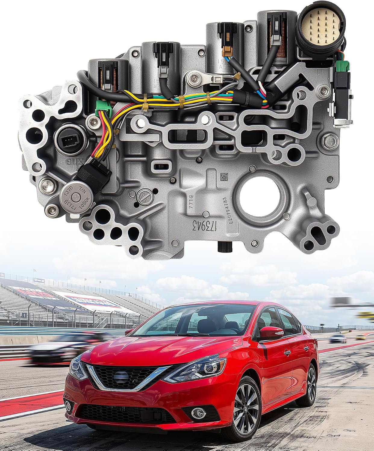
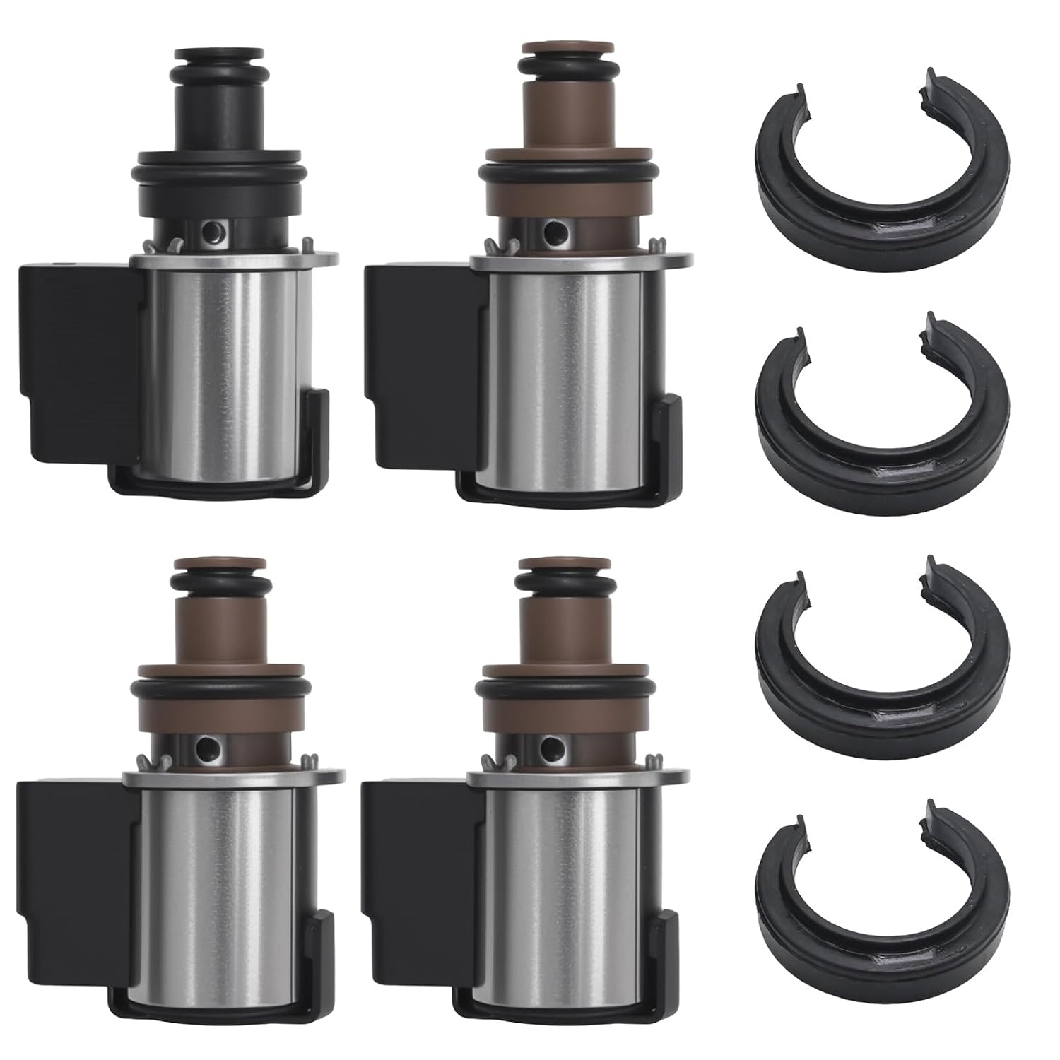
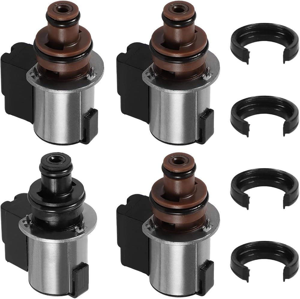
CVT hydraulic systems use pressure control solenoids to regulate both ratio change and belt clamping pressure. When these solenoids wear or fail, the result is inconsistent clamping pressure. Low clamping pressure causes belt slip. High clamping pressure reduces efficiency and causes belt wear through different mechanisms. Erratic clamping pressure causes the belt to track inconsistently across the pulley surface and generates localized wear.
Put a gauge on it before you condemn a solenoid. These are not conventional-automatic pressures. Per Sonnax's CVT in-vehicle isolation procedure for the Jatco units, the pulley circuits peak around 870 psi (5,998 kPa), so you need a gauge rated to at least 1,000 psi (7,000 kPa) and the correct port adapter — a 300 psi automatic-transmission gauge will not survive the test. The targets Sonnax publishes give you something to compare against: at hot drive idle the secondary pulley should read about 125 psi with line pressure near 130 to 150 psi; under acceleration the secondary pulley climbs from roughly 180 psi to 285 psi with line pressure at 150 to 240 psi. Forward and reverse clutch circuits cap near 218 psi, TCC apply near 138 psi, and lube and cooler near 60 psi.
The pattern matters more than any single number. If every circuit reads low, Sonnax points at the pump flow control valve rather than the individual solenoids — the oversized replacement valve is the fix. If only the pulley circuits are low while clutch and lube pressures are normal, the fault is downstream in the pulley control circuit. Gears Magazine's Jatco CVT pressure diagnostics coverage makes the same point: the primary and secondary pressure PIDs are direct measurements of pulley pressure, which is why they separate a pump problem from a control problem faster than any code will.
Ratio Control Solenoid Failure
Ratio control solenoid failure results in the CVT getting stuck at a fixed ratio — effectively operating like a one-speed transmission. This is the CVT equivalent of limp mode. The vehicle will move but acceleration and fuel economy are severely compromised. Codes specific to ratio control circuit failures point directly to this solenoid on most applications.
There is a trap here that costs shops a second teardown. On a JF011E, ratio is controlled by a stepper motor acting on the ratio control valve through a lever that indexes to the primary pulley follower. Transmission Digest documents a Dodge Caliber that came in with P0842 (primary pulley pressure sensor, low circuit) and left with a brand-new valve body and a P0730 incorrect-gear-ratio code, stuck in one ratio. The valve body was not defective — the ratio control valve lever had come out of index during installation. The valve body has an access hole specifically so you can hold that lever in position with a pick during removal and reassembly. Skip that step and you have built yourself a ratio code.
Worn solenoid feed circuits cause the same confusion from a different direction: leakage past the solenoid regulator valve drops feed pressure and sets ratio, pressure sensor, and solenoid A or B codes that all read like failed electronics. Sonnax addresses that on the Jatco/Nissan units with a solenoid regulator valve kit that fits a wear-resistant sleeve and new springs into the worn bore. Vacuum-test the bore before you buy a solenoid.
Why Fluid Matters More on a CVT
The Fluid Is the Friction Material
In a conventional automatic transmission, friction is generated by the clutch pack friction material itself. The fluid is a medium that transmits pressure and lubricates components, but the friction material in the clutch disc is doing the work. In a CVT, the fluid is part of the friction interface. The belt-to-pulley friction that transmits torque depends on the viscosity and friction coefficient of the fluid. When CVT fluid degrades, the friction coefficient changes, belt clamping efficiency drops, and slip events increase.
Service Intervals Are Not Optional
Most manufacturers publish CVT fluid service intervals of 30,000–60,000 miles for severe duty. Many CVTs come into shops with 100,000+ miles on original fluid. By that point, the fluid viscosity has dropped, the friction modifiers are depleted, and the metal particles from normal wear are in suspension throughout the fluid. Every mile driven on degraded CVT fluid accelerates belt, chain, and pulley wear.
When a customer asks why their CVT failed at 80,000 miles, the honest answer in most cases is: deferred fluid maintenance combined with a design that has tighter operating tolerances than a conventional automatic. The fluid service interval is not a suggestion on these units.
There is a diagnostic payoff to the same fact. Because the fluid is part of the friction interface, a CVT with correct pressures and degraded fluid still slips — which is why pressure testing comes with a fluid-condition check attached, not instead of one. And noise tells you something pressure will not: Sonnax notes that a whine on acceleration with normal fluid level and normal pressures is a bearing, and that noise staying constant while engine RPM rises points at the secondary or final drive bearing, while noise that tracks engine speed points at the primary pulley bearing.
Need parts for this job?
Rebuild kits, hard parts, solenoids, valve bodies, filters, gaskets and the correct fluid for this unit — shipped fast from the USA on secure checkout.
Shop CVT parts →