A 5R55W or 5R55S comes in with a flare on the 1-2, a lazy reverse that only shows up hot, and a couple of ratio codes stored. The shop throws a solenoid block at it. Then a valve body. Then a rebuild kit with fresh bands. Ninety days later the bands are cooked again and nobody can explain why.
The reason is almost always the same, and it is not a part you can buy off a shelf: the servo apply pin bores in the aluminum case are worn oval, and every drop of apply and release oil for both bands passes through those bores. You can replace every soft part in the unit and the pressure will still bleed away into the case.
This is how that circuit actually works, how to tell servo bore wear apart from the two failures constantly mistaken for it, and how the case gets repaired instead of replaced.
The short version: Apply oil for both the overdrive and intermediate servos is fed up through the case bridge and out through the hollow servo pin. The pin has to seal in the case bore. When the bore wears, apply oil dumps into the barrel area and release oil cross-leaks into the apply circuits and exhausts at the shift valves — which is why worn bores produce 1-2, 2-3 and 4-5 flares, codes 732/733/735, band lining failure and delayed reverse, per Sonnax. The repair is a wear-resistant aluminum sleeve (Sonnax 56361J-01K) reamed in with tooling that pilots off the pin bore centerline, not the piston bore.
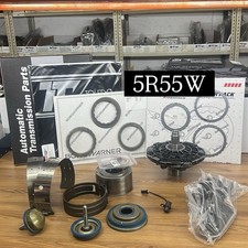
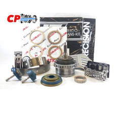
Know Which Unit Is On Your Bench First
The 5R55 family is three different transmissions wearing similar castings, and mixing parts between them creates problems that look like wear. Per Sonnax's teardown guide by Bob Warnke, the 5R55N ran from '99–'02 in the Jaguar S-Type, Lincoln LS and Thunderbird behind the 3.0/3.9L engines. The N was replaced by the S in 2003 in the Lincolns and Thunderbirds. The W showed up in Explorers and Mountaineers for '02–'03 before giving way to the S in '04–'05.
Three field IDs worth memorizing:
- External: the N has two cast bosses just behind the intermediate servo cover, the closer one tapped for PCC. The W/S has only one boss, for the PCC pressure port. In the vehicle you cannot see it, but you can feel it.
- Under the pan: the N carries a base plate similar to a 4R70W over the lower valve body, plus a reverse pressure (RP) switch. The 5R55W/S solenoid has no terminals for the RP switch, and the circuits are different.
- Hard parts: Sonnax identifies the W by a 24-tooth overdrive sun gear and the S by a 38-tooth one. The N also has an intermediate clutch the W and S do not, which ATRA points out is a big part of why so few parts actually interchange.
Only a few N parts will drop into a W or S, and most of the rest cause trouble if you force them. Confirm the unit before you order anything.
How the Servo Circuit Actually Works
This is the part that makes the failure make sense. In the 5R55N/W/S, the servo pin is hollow, and it is a working oil passage, not just a pushrod.
Sonnax describes the flow this way: servo apply oil is fed through the center of the case bridge and into the servo pin, where it reacts on the cover side of the piston. Servo release pressure is fed through the case and into the spring side of the piston. Both circuits depend on a steel pin sealing against an aluminum case bore.
Now put miles on it. The overdrive servo is used for second gear as well as fifth, which means it cycles twice on every single trip from a stop up to cruising speed. A steel pin oscillating in an aluminum bore thousands of times a week does exactly what you would expect: it wears the bore oval and scores it.
Once that clearance opens up, two separate leaks start:
- Apply oil leaks into the barrel area of the case. That directly degrades shift timing and servo/band apply pressure. The band no longer clamps with full force, so it slips, glazes and burns.
- Release oil cross-leaks into the apply circuits and exhausts at the shift valves. This is the one that fools people, because it means a servo can be applying and releasing at the same time.
There is a third consequence most techs never connect: in reverse, both servos are charged from the release side. So pin bore wear shows up as delayed reverse — the complaint that usually gets blamed on a pump or a solenoid.
Sonnax lists the full symptom set for this failure as 1-2, 2-3 and 4-5 flares, gear loss, codes 732, 733 and 735, band lining failure, and loss of overdrive and intermediate servo control. If you are staring at P0732/P0733/P0735 on a 5R55W or S, the case bores belong at the front of the diagnostic list, not the back.
One more thing to expect on these units: Sonnax notes the N, W and S are prone to foaming the fluid in the sump from excess exhaust and valve body wear. That gives you fluid out the vent and a false fill reading, which sends people chasing a leak that does not exist.
5R55W/5R55S Servo Piston Kit (1999-Up)
New pistons and seals for the overdrive and intermediate servos. Replace these any time you sleeve the pin bores — a hard, torn or delaminated piston will cross-leak release oil even in a perfect bore. Available at our sister store CoreTransmissionParts, or browse the full 5R55W parts collection.
Shop the 5R55W Servo Piston Kit →Two Failures Constantly Misdiagnosed As Servo Bore Wear
1. Worn VFS modulator bores in the valve body
This is the single most useful diagnostic sentence in the Sonnax 5R55 literature, and it should stop a lot of unnecessary case work: often the solenoid or the servo pin bore gets blamed as the culprit, but the real problem is that the VFS modulator valves cannot supply enough pressure.
Sonnax gives a wear order for a quick visual read on a 5R55W/S valve body. Start at the TCC modulator bore, then the main regulator bore — those wear first because of how hard they work. As cycle rate climbs (much higher in city traffic), the VFS 1, 2 and 3 modulator bores wear, and that reduces clutch and servo pressure. The adaptive strategy in the PCM papers over it for a while. Once the wear passes what adapt can compensate for, you get gear ratio codes and slippage — the same complaint list a worn pin bore produces.
So inspect the valve body bores before you pull the case apart. Sonnax's fix for that specific location is the Oversized VFS Modulator Control Valve Kit 56947J-19K (it fits either of the two VFS locations) with tool F-56947J-TL19. Sonnax's published cure list for that kit is flare shifts, pressure control out-of-range codes and low line pressure — read that list again and notice how well it overlaps with the servo bore symptom list.
2. A leaking servo piston on the release side
ATRA's Mike Brown lays out a test for this in GEARS that takes about two minutes and is worth its weight in labor hours. Both servo pistons use release oil to hold them off when the band is not supposed to be applied. The springs help, but they are not enough on their own: release pressure acting on the big side of the piston is what actually holds the band off.
The test, straight out of the article:
- Start the engine and raise the vehicle.
- Put the transmission in Drive, running.
- Have a second tech try to turn each band adjustment screw in.
In Drive, both bands should be off, so both adjusting screws should turn in without resistance. If one is tight, that band is being applied when it should be released. Brown's point is that this is exactly where techs go down the wrong road: they replace the valve body, then the solenoid block, and the adjustment is still tight — because the fault is a hard, torn or delaminated servo piston letting release oil cross over and become apply oil.
Here is why it hides so well: these servos air check fine. The apply side is not the problem. The release side is. A bad release-side leak gives you a bind in reverse and manual low plus wrong gear starts; a small leak gives subtler wrong-gear behavior. Air checking the apply side will never show it.
Brown's other two quick calls on this unit belong in the same mental file: no engagement, slow engagement or pump noise sends you to the blow-off valve in the pump; multiple codes with missing gears sends you to a broken circuit in the solenoid block.
Repairing the Bore Instead of Buying a Case
The case is the expensive part, and for years a scored pin bore condemned it. The obstacle was never the reamer — it was fixturing. There was no reliable way to hold tooling concentric to the pin bore centerline, because the servo piston bore and its seal surfaces are not necessarily concentric with the pin bore they surround.
Sonnax's answer is a two-piece system:
- 56361J-01K — the Overdrive & Intermediate Servo Pin Bore Sleeve Kit. It contains one overdrive repair sleeve and one intermediate repair sleeve, made from a highly wear-resistant aluminum, and it refurbishes the case to proper clearance with the servo apply pins. One kit covers 5R55N, 5R55W and 5R55S.
- S-56361J-TL tool kit, used with the SERVO-FIX reaming fixture. The fixture clamps to the case and uses a floating bearing guide so the pilot and reamer align from the pin bore centerline, not the servo piston bore. Sonnax is explicit that this means reaming is not affected by irregular piston or seal concentricity. One fixture and one tool kit handle both the overdrive and intermediate locations on all three units.
Ford's own service bulletin procedure for this condition follows the same logic: measure both servo pin bores and sleeve the case where they are oversize, because oversize pin bores cost servo pressure and take the bands with them. If you are doing the OE version of the repair, note that the sleeve has to be cross-drilled to line up with the servo apply holes in the case. Skip that step and you have a no-shift condition on a transmission you just spent a day rebuilding.
If you do not own the fixture, this is a legitimate reason to farm the case out to a shop that does. What is not legitimate is installing new bands into worn bores and calling it a rebuild.
Fluid, Fill and the Solenoid Trap
Two fluid-related landmines on this family, both documented by Sonnax.
The early Mercon V problem. The factory ATF fill in 5R55E, W, S and N units built before May 2005 used an early Mercon V that degraded the solenoids. Ford released an interim additive package — 4L2Z-19B546-AB, fluid XL-11, under bulletin FSA 04B22 — to be installed in customer vehicles and new inventory. The permanent fix was a revised Mercon V, XT-5-QM, in the black quart container. The practical takeaway for a rebuild: if any trace of the old fluid survives your service, the service life of the next solenoid is already on the clock. Flush it properly.
Loss of prime. Replacement solenoid assemblies are tested and shipped wet, but that lubricant drains off during handling. Sonnax's instruction is to fill the circuits with new Mercon V or the XL-11 additive and pull fluid through the solenoid with vacuum before installing it. If it still misbehaves, run the vehicle up to temperature, let it cool, and road test again later.
Also, do not reuse the solenoid base plate or filter across units. Sonnax is blunt about this: the solenoid assembly appears to interchange between N/W/S, but the base plate and the filter are the critical components, and mixing them costs you reverse, TCC apply and solenoid oil pressure. The filter is part of the gasket, lives under the aluminum base plate and is a serviced item — keep it far from solvents if you plan to reuse it, or the silicone bead will never be the right size again.
Fill and level specs
There is no dipstick and no fill tube on these. Fill and level check happen through a T30 Torx plug in the center of the pan drain plug, using Ford special tool 307-437 or equivalent.
| Item | Spec |
|---|---|
| Fluid | Mercon V (revised, XT-5-QM) |
| Dry fill, 3.0L & 3.9L applications | 11.2 quarts |
| Dry fill, 4.0L & 4.6L applications | 12.4 to 12.7 quarts |
| Level check temperature | 80°F–120°F (27°C–49°C), engine idling near 650 rpm, in Park |
| Oil level check plug torque | 89 in-lb (10 Nm) |
| Pan drain plug torque | 19 ft-lb (26 Nm) |
Check level for a steady, translucent stream or a rapid drip from the check hole, not a gush. Overfilling is the number one cause of what looks like a converter housing leak on these: the excess gets pushed out the vent and runs down the bell. Combine that with the sump foaming Sonnax describes and it is easy to talk yourself into a front seal you do not need.
After a solenoid service or a rebuild, Ford units built after 2002 use adaptive strategy, so perform a KAM reset and a relearn drive cycle: accelerate moderately to 50 mph so the unit reaches 5th, hold speed and throttle steady at least 15 seconds, tap the brake to trigger the lamps, hold another 5 seconds, then stop for at least 20 seconds. Repeat that cycle at least five times, then re-run a quick test. While you are there, inspect the grounds at the battery and PCM and clean the mass airflow sensor — Sonnax flags all three as contributors to complaints blamed on the transmission. Our adaptive relearn walkthrough covers the procedure in more detail.
The Pressure Numbers Worth Knowing
If you are testing rather than guessing, Sonnax publishes the regulated values for the converter side of this unit:
- Converter release oil is limited to 130 psi by the converter regulator valve. That release oil holds the TCC piston off the cover, supplies charge pressure, then flows to the cooler.
- TCC solenoid pressure is supposed to be limited to 72 psi by the solenoid regulator valve. If that bore is worn at the inboard end, pressure keeps climbing at the modulator valve sleeve. Slip goes down, which looks like a fix, but the TCC piston starts deflecting and the converter fails.
- Once the TCC control valve strokes, modulated line pressure becomes converter apply pressure, and line on these runs 160–250 psi and up. That is how a worn regulator bore turns into a destroyed converter.
- A back pressure valve maintains 8–12 psi on the release oil to help control TCC slip and lube pressure. Small valve, real consequences.
For valve body condition, Sonnax recommends the Wet Air Test (WAT), which can be run in the vehicle or on the bench, before you commit to a bore repair. Pair that with a mechanical gauge on the line pressure tap; our line pressure testing guide covers the setup.
The Order of Operations
On a 5R55W or 5R55S with flares, ratio codes or a delayed reverse, work it in this order and you stop replacing parts that were never bad:
- Confirm the unit (N vs W vs S) by the case boss count and the base plate. Do not order until you know.
- Verify the TCM is commanding the right gear before touching the transmission. Codes in memory forcing failsafe, an out-of-adjustment manual lever position sensor, and a vehicle speed sensor picking up a stray charging or ignition signal will all produce wrong-gear behavior on a healthy transmission.
- Run the band adjustment screw test in Drive with the engine running. A tight screw means a servo piston is leaking release oil, and it will still air check fine.
- Check line pressure and wet air test the valve body. Look hard at the TCC modulator, main regulator and VFS modulator bores before you condemn the case.
- Measure both servo pin bores. If they are oversize, sleeve them with 56361J-01K using the SERVO-FIX fixture, and cross-drill to the case apply holes.
- Replace the servo pistons, seals and bands, because whatever burned them is only now fixed.
- Flush the old fluid completely, prime the new solenoid with vacuum, fill to spec at 80–120°F, and run the relearn drive cycle.
The bands on this unit are not weak. They burn because the pressure that was supposed to clamp them leaked into an aluminum bore that wore out doing its job twice per trip. Fix the bore and the rest of the rebuild finally gets to do its job.
More on this family: 5R55S and 5R55W common problems, 5R55 harsh and delayed shifts, and testing solenoids without a factory scan tool.
Sources
- Sonnax — Overdrive & Intermediate Servo Pin Bore Sleeve Kit, 56361J-01K. Backs the apply/release oil path through the case bridge and hollow pin, the barrel-area leak and shift-valve cross-leak, delayed reverse from release-side charging in reverse, the symptom and code list (732/733/735, flares, band lining failure, loss of servo control), the sump foaming note, and the sleeve kit contents and S-56361J-TL tooling. sonnax.com/parts/2207-overdrive-intermediate-servo-pin-bore-sleeve-kit
- Sonnax — "Figuring Out the 5R55 Alphabet," Bob Warnke. Backs the N/W/S model years and applications, the one-boss vs two-boss and base plate identification, the 24-tooth (W) and 38-tooth (S) overdrive sun gears, the TCC/main regulator/VFS modulator bore wear order and the VFS misdiagnosis, the solenoid base plate and filter warning, the pre-May-2005 Mercon V issue with additive 4L2Z-19B546-AB / bulletin FSA 04B22 and revised XT-5-QM, solenoid loss of prime, the wet air test recommendation, and the 130 psi / 72 psi / 8-12 psi / 160-250 psi values. sonnax.com/tech_resources/195-figuring-out-the-5r55-alphabet
- Sonnax — Servo Pin Bore Reaming Fixture, SERVO-FIX. Backs the fixturing problem, the floating bearing guide, and that the pilot and reamer align from the pin bore centerline rather than the servo piston bore so irregular piston or seal concentricity does not affect the ream. sonnax.com/parts/3041-servo-pin-bore-reaming-fixture
- Sonnax — Ford 5R55S, 5R55W Valve Body Layout. Backs the Oversized VFS Modulator Control Valve Kit 56947J-19K (fits either of two locations, tool F-56947J-TL19) and its published cure list of flare shifts, pressure control out-of-range codes and low line pressure. sonnax.com/tech_resources/584-ford-5r55s-5r55w-valve-body-layout
- ATRA / GEARS Magazine — "5R55N with Wrong Gear Starts and Bindups? Look for a Faulty Servo," Mike Brown. Backs the intermediate clutch difference between N and W/S, the band adjustment screw test in Drive, release oil holding the pistons off, the delaminated piston cross-leak, why these servos air check fine, and the pump blow-off valve and solenoid block circuit calls. gearsmagazine.com/magazine/5r55n-with-wrong-gear-starts-and-bindups-look-for-a-faulty-servo
- ATRA / GEARS Magazine — "Going Nowhere Fast... 5R55W Delayed Forward Engagement," Rob Faucett. Backs the typical bench findings on these units (servo pin wear, burnt bands, destroyed overdrive planets) and the forward engagement circuit detail behind delayed-engagement diagnosis. gearsmagazine.com/magazine/going-nowhere-fast-5r55w-delayed-forward-engagement
- 5R55S & 5R55W Installation Guide (remanufacturer service documentation). Backs the no-dipstick fill procedure through the T30 plug with Ford special tool 307-437, dry fill capacities of 11.2 quarts (3.0L/3.9L) and 12.4-12.7 quarts (4.0L/4.6L), the 80-120°F level check near 650 rpm idle, the 89 in-lb level plug and 19 ft-lb drain plug torques, the overfill-out-the-vent warning, and the KAM reset relearn drive cycle. static.summitracing.com/global/images/instructions/vre-7800a-4s.pdf