A 5R55 that bangs into reverse, takes three seconds to find drive once warm, or flares on a shift is a frustrating unit to chase: most of these symptoms have three or four legitimate causes, and most are hydraulic rather than electrical. The default move — hang a solenoid pack on it — works often enough to be tempting and fails often enough to be expensive.
Step 0: Establish which 5R55 is in front of you
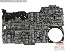
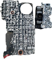
The 5R55 badge covers units that do not share parts, and putting an N part in a W or S is a known way to create the complaint you were hired to fix. Per Sonnax's Bob Warnke, the 5R55N ran 1999–2002 in the Jaguar S-Type 3.0/4.0, Lincoln LS and Thunderbird 3.0/3.9, with the S replacing it in 2003. The W appeared in Explorers and Mountaineers for 2002–2003 before the S took over for 2004–2005. Few parts actually interchange. Identify it externally: the N has two cast bosses just behind the intermediate servo cover, the closest tapped for PCC, while the W and S have only one. With the pan off, the N carries a base plate similar to a 4R70W plus a reverse pressure switch; the W/S solenoid has no RP switch terminals. Between W and S, the hard-part difference that matters is the overdrive sun gear: 24 teeth on the W, 38 on the S.
One more trap: the 5R55E, 5R44E, 4R55E and 4R44E are a different family entirely. A Sonnax EPC and engagement control kit promising to cure delayed forward and no reverse is listed for those units, not for an S or W.
Step 1: Understand the engagement before you diagnose it
Most 5R55S/W engagement complaints get misdiagnosed because the factory hydraulic diagrams show only the static gear application — the circuit with the gear already engaged. They do not show the transition, and the transition is where harsh and delayed engagements live. Jesse Zacarias of Elec-Tran Diagnostics laid this out in Transmission Digest.
The unit has four on/off shift solenoids, one PWM solenoid for TCC, and three variable force solenoids (PCA, PCB, PCC). The shift solenoids align valves so the VFS solenoids can control apply and release rate. In Park, Reverse, Neutral and Drive their state does not change: only PCA, PCB and PCC participate in engagement.
Reverse
The range sensor tells the PCM you selected reverse. The PCM modulates PCB at about 0.5 amp, and that VFS 2 pressure holds the reverse engagement control valve down, blocking mainline out of the direct drum. SSA being on holds the direct clutch control valve up, letting PCC modulation pressure reach the direct clutch through the reverse pressure modulator valve — the servo and torque phase. PCC pressure also feeds the bottom of that valve; as the PCM lowers PCC amperage, the pressure rises until it overcomes PCB on top, strokes the valve up and opens mainline into the direct drum. That is the inertia phase. Roughly two seconds start to finish.
Forward
Same architecture. PCB at about 0.5 amp sits on top of the forward engagement control valve, blocking mainline from the forward drum. The PCM lowers PCA amperage, VFS 1 pressure climbs and feeds the drum through that valve, then acts on the bottom of the valve, overcomes PCB and strokes it, dumping mainline straight in. Again, about two seconds.
Read those as a diagnostic tool: engagement is a two-stage handoff from modulated pressure to mainline. Harsh means the handoff came too early or with too much behind it. Delayed means the modulated stage is too weak to fill the drum, or the control valve never strokes because the pressure holding or moving it is leaking off. It also explains why a bad range sensor prevents engagement outright: the whole VFS sequence keys off that signal.
Step 2: Fluid level, done the way the unit requires
There is no dipstick and no fill tube. Level is set from a T30 torx plug in the center of the pan drain plug, using Ford special tool 307-437 or equivalent to pump fluid in. Guessing produces both complaints on the list: low fluid delays engagement, overfill aerates and makes pressure erratic.
Dry fill runs about 11.2 quarts behind the 3.0 and 3.9 liter engines, 12.4 to 12.7 behind the 4.0 and 4.6. Pump fluid in, start the engine, idle around 650 rpm and bring fluid to 80–120°F (27–49°C) on the scan tool. Brake applied, move through every range pausing five seconds in each, then back to Park. At idle in Park, pull the check tool: if nothing comes out, add until it does; if it does, let it drain to a steady translucent stream or rapid drip, then plug it. Torque: check plug 89 in-lb (10 Nm), drain plug 19 ft-lb (26 Nm).
Before you chase a leak: overfilling is the leading cause of what looks like a converter housing leak, because fluid goes out the vent rather than past a seal. A worn valve body also foams the sump, giving a false high reading. Top off a unit that is aerating and you have made it worse.
Ford 5R55W/5R55S ATF Fill Adapter (OTC 6604 / 307-437)
Threads into the level check plug so you can pump fluid in and set level to spec.
View the fill adapter →The fluid itself
Mercon V, and the history matters. Factory fills on 5R55E, W, S and N units before May 2005 used an early formulation that degraded solenoids and produced delayed and harsh engagements. Ford released an interim additive package, part 4L2Z-19B546-AB (fluid XL-11), under bulletin FSA 04B22; the final resolution was a revised Mercon V, XT-5-QM, in the black quart container. Leave any trace of the old fluid in during a service and you are shortening the life of the next solenoid.
Step 3: The free mechanical check that fixes harsh reverse
Before the valve body comes out, check the shifter linkage and its alignment marks. If manual lever alignment is even slightly off, the PCM reads the reverse signal and boosts line pressure before the manual valve reaches reverse — a hard bang into reverse from a transmission with nothing wrong inside it.
- Verify the linkage lines up through every range. If not, put the shifter in manual low, pop the cable off the manual arm, pull the lock tab outward with a pick and slide it up, center the lock on the manual arm ball, snap it on, slide the tab down, then confirm in neutral.
- Still off? Check the cable bracket for bending and line it to the witness marks where the bolts pass through, then check the column — slop in the handle means a stretched cable or worn shifter mechanism, and that is a column kit, not a separate part.
Step 4: What to watch on the scan tool
Start with the range sensor. After that, gear ratio codes are the wear indicator. Codes 732, 733 and 735 point at servo and band control, which on this unit usually means servo pin bore wear rather than a burnt band. Units built after 2002 adapt, so the PCM has been compensating for falling pressure for a while; by the time it sets a ratio code, the wear is not marginal.
Step 5: Wet air test the valve body
The wet air test is the most efficient way to grade a 5R55N/W/S valve body, in the vehicle or on the bench. Remove the solenoid base plate and reattach it over the separator plate, then inject ATF with 40–60 psi of air. On a good valve body the valves stroke, with no excessive leakage past them and no bubbling from the exhaust slots.
For a fast visual read, start at the TCC modulator bore, then the main regulator bore — those wear first, being the most active. Then check the VFS 1, 2 and 3 bores. As cycle rate climbs (city driving is the worst case) those bores wear and clutch and servo pressure falls. Adaptive strategy hides that until it cannot, then you get ratio codes or slippage. Warnke's point bears repeating: the solenoid or the servo pin bore takes the blame when the VFS modulator valves are the ones that cannot supply enough pressure.
Step 6: If the complaint is specifically delayed reverse
Check the low/reverse servo control valve. It lives in the low/reverse servo under a threaded end cap and regulates flow to apply the servo. Stuck, it fills the servo slowly and you get delay. Hidden under that cap, it gets skipped constantly during a rebuild, and it gets contaminated by how shops clean parts: run the housing through a hot pressure washer and water, soap and dirt collect in the bore. Pull the valve and spring every time and check that it moves freely dry.
The other reverse-specific cause is servo pin bore wear in the case. Apply oil feeds through the case bridge into the servo pin and acts on the cover side of the piston; as the bore wears, that oil leaks into the barrel area, hurting shift timing and band apply pressure. Release pressure feeds the spring side, and as wear increases it cross-leaks into the apply circuits and exhausts at the shift valves. In reverse both servos are charged from the release side, which is exactly why pin bore wear reads as delayed reverse. Symptoms: 1-2, 2-3 and 4-5 flares, gear loss, codes 732/733/735 and band lining failure. Sonnax sleeve kit 56361J-01K with S-56361J-TL tooling salvages the case, its pilot and reamer aligning from the pin bore centerline rather than the servo piston bore. We covered that failure in depth in our 5R55S/5R55W problems write-up.
Step 7: The leak that survives a good rebuild
A case worth memorizing, from GEARS: a 2006 Explorer with a 5R55W came in with a severe delay engaging forward once warm, driven that way over a month and by then binding in reverse and pulling forward in neutral. Solenoid and sensor readings all checked normal, and a full inspection — forward drum, sealing rings, center support, case, separator plate and gasket — turned up nothing but a damaged forward clutch.
The root cause was a leak between an end plug and the valve body at the forward engagement control valve — the valve from Step 1. The fix was O-ringed end plugs, verified by vacuum test before reassembly. Delayed forward with clean electrical data and a clutch cooked for no visible reason: that is where to look.
Step 8: Do not just swap the solenoid pack
The solenoid assembly appears to interchange between N, W and S, but the base plate and filter are the critical pieces. Mix those and the unit loses reverse, TCC apply and solenoid oil pressure. The filter is part of the gasket, sits under the aluminum base plate and is a serviced item — if you reuse it, keep it away from solvents or the silicone bead will never be right again.
There is also a failure mode unique to new solenoids: loss of prime. VFS solenoids ship with fluid in them, but handling drains it off. Before installing the assembly, fill the circuits with fresh Mercon V and pull fluid through with vacuum. If a new solenoid still misbehaves, run the vehicle hot, let it cool and road test again before condemning it.
And if you do replace the pack, make sure it's the right one for the year. Per ATRA's 2013 seminar write-up on 5R55W/S erratic operation, 2002-2003 Ford units (and the 2003 Lincoln 5R55S) take the early pack, Ford 1L2Z-7G391-AG, while 2004-on Ford units (and 2004-2006 Lincoln) take the late pack, with Ford recommending only the updated 9L2Z-7G391-A. ATRA measured a 4 psi difference in PCA output at 0.6 amps between pack designs, which works out to roughly 30 psi of mainline, enough to cause soft 2-3 flares and harsh downshifts by itself. Ford's service procedure torques the eight solenoid body bolts to just 71 lb-in (8 Nm) in sequence and warns that overtightening damages the solenoid body. Our 5R55S shift solenoid guide covers pack diagnosis in detail.
Step 9: Delay that clears with rpm is a pump problem
If engagement is delayed at idle but returns as soon as revs come up, suspect the line control valve in the pump. A plunger stuck open exposes pump output to the suction side, so at idle the leak wins; once pump volume exceeds the leak, engagement comes back.
In-vehicle test: select reverse and disconnect the wiring to the solenoids. That commands maximum line pressure and will often force the plunger shut, confirming it. Do not hold high rpm or drag the test out — the servos and seals see excessive pressure while you do it. On the bench, feed 100 psi of air into the line control port; a distinct pop means the plunger was stuck open. No other circuit should leak, and if one does, the canister is loose in its bore, reducing pump output and line pressure.
After the repair: reset and relearn
Ford units built after 2002 adapt, and a repaired transmission running old adapts will feel wrong. Record and erase codes, perform a KAM reset, warm the engine and confirm fluid level. In Drive, accelerate moderately to 50 mph so it reaches fifth and hold speed and throttle steady at least 15 seconds. Still in fifth, lightly apply and release the brake to trigger the brake lights, then hold steady another 5 seconds. Brake to a stop and sit at least 20 seconds. Repeat at least five times, then run a quick test and correct any continuous DTCs. Back on the hoist, reconfirm level and check for leaks.
5R55 rebuild kits, filters and pan gaskets, solenoid packs, hard parts, and the fill adapter this procedure requires — shipped fast from the USA.
Shop 5R55 parts →Sources
- Sonnax — "Figuring Out the 5R55 Alphabet," Bob Warnke, September 19, 2007. Backs the N/W/S model years and applications, the external identification by cast bosses behind the intermediate servo cover, the 4R70W-style base plate and reverse pressure switch on the N, the 24-tooth versus 38-tooth overdrive sun gear, the TCC modulator and main regulator bores wearing first, VFS 1/2/3 modulator bore wear reducing clutch and servo pressure, the solenoid base plate and filter interchange warning, the pre-May-2005 Mercon V problem with additive 4L2Z-19B546-AB and bulletin FSA 04B22, loss of prime on replacement VFS solenoids, the wet air test at 40–60 psi, and the in-vehicle and bench tests for the pump line control valve. sonnax.com
- Transmission Digest — "Understanding the 5R55S/W Initial Engagements," Jesse Zacarias, November 1, 2012. Backs the solenoid count (four on/off shift solenoids, one PWM TCC solenoid, three variable force solenoids), the roughly 0.5 amp PCB command, the reverse and forward engagement control valve sequences including the servo/torque phase and inertia phase handoff to mainline, the approximately two-second engagement time, and why a failed transmission range sensor prevents engagement. transmissiondigest.com
- Sonnax — Overdrive & Intermediate Servo Pin Bore Sleeve Kit 56361J-01K. Backs the servo pin bore wear mechanism (apply oil through the case bridge into the pin, leaking to the barrel area as the bore wears; release oil cross-leaking into apply circuits and exhausting at the shift valves; both servos charged from the release side in reverse), the symptom list of 1-2, 2-3 and 4-5 flares, gear loss, codes 732/733/735 and band lining failure, the sump foaming and false fill indication, and the S-56361J-TL tooling aligning from the pin bore centerline. sonnax.com
- Sonnax — "Ford 5R55N/S/W Delayed Reverse," January 1, 2013. Backs the stuck low/reverse servo control valve as a cause of delayed reverse, its location under a threaded end cap in the low/reverse servo, the slow servo fill mechanism, and the hot pressure washer contamination warning. sonnax.com
- GEARS Magazine (ATRA) — "Going Nowhere Fast: 5R55W Delayed Forward Engagement." Backs the 2006 Explorer case study: severe delayed forward engagement when warm progressing to bind in reverse and pull forward in neutral, normal solenoid and sensor readings, forward clutch as the only damage found, and the root cause being a leak between the end plug and the valve body at the forward engagement control valve, corrected with O-ringed end plugs and confirmed by vacuum test. gearsmagazine.com
- 5R55S & 5R55W Ford Automatic Transmission Installation Guide (remanufacturer installation document, doc. 432718). Backs the T30 torx fill/level check plug and Ford special tool 307-437, the dry fill capacities of 11.2 quarts behind the 3.0/3.9L and 12.4–12.7 quarts behind the 4.0/4.6L, the 80–120°F (27–49°C) check window at roughly 650 rpm idle, the translucent stream/rapid drip level indication, the 89 in-lb (10 Nm) check plug and 19 ft-lb (26 Nm) drain plug torques, overfill venting mistaken for a converter housing leak, the harsh-reverse shifter linkage alignment procedure, and the KAM reset and drive cycle. Installation guide (PDF)
- ATRA — 2013 Technical Seminar manual, "Ford 5R55W/S Erratic Transmission Operation" (pp. 112-120). Backs the early (1L2Z-7G391-AG) and late (4L2Z-7G391-AA, updated 9L2Z-7G391-A) solenoid pack applications by year, and the 4 psi PCA difference at 0.6 A equating to about 30 psi of mainline and causing 2-3 flares and harsh downshifts. atracom (PDF)
- Ford Motor Company service information — "2002 Automatic Transmissions Servicing - Explorer & Mountaineer" (5R55W/S), via Mitchell Repair Information. Backs the eight solenoid body bolts, the 71 lb-in (8 Nm) torque and sequence, and the overtorque damage caution. Ford/Mitchell service procedure (PDF)