A 200-4R that bangs into second at light throttle, or takes two seconds to grab Drive after you pull the lever out of Park, is telling you something specific. The hard part is that the 200-4R gives you almost nothing to scan. There is no shift solenoid, no TCM, no adaptive learn table. Shift timing comes from a mechanical governor reading output speed and a throttle valve cable reading engine load, and shift feel comes from line pressure, accumulator action, and orifice sizing in the valve body. The only electrical component in the shift story is the TCC lockup solenoid, and it does not shift the unit.
That is good news: the diagnosis follows a fixed order, and every step is verifiable with a gauge, a road test, and a vacuum tester. What follows is the order I work in.
Step 1: Verify the TV Cable Before You Touch Anything Else
The throttle valve cable on the 200-4R does two jobs at once. It sets throttle pressure, which feeds the boost valve and raises line pressure with load, and it sets shift timing by opposing governor pressure at the shift valves. One cable, both symptoms. That is why a cable that is out of adjustment can present as harsh shifts, delayed shifts, early shifts, or a burned unit six months later, depending on which direction it is off.
There is a design problem underneath this that a lot of techs never hear about. Per Sonnax, in most GM and Ford transmissions with cables — TH200, 200-4R, TH200C, 4L60 (700-R4), Ford AOD and AXOD — the throttle valve cable pulls itself out of adjustment at wide-open throttle. The cause is the geometry of the throttle shaft lever: there should be a specific degree of movement of the attachment element pivot point between closed and wide open throttle, and a specific distance between the pivot points of the attachment element and the throttle shaft lever. When either of those exceeds spec, the cable gets pulled past its adjustment at full throttle and stays there. Sonnax sells a corrector kit (AS1-01K) that adds a spring and stop so the excess cable pull is absorbed rather than yanking the adjuster. If your car has an aftermarket carb, an aftermarket throttle bracket, or a swapped engine, assume the geometry is wrong until you prove otherwise.
The adjustment procedure that actually works
Paul Townsend's write-up in Transmission Digest lays out the sequence for the THM700-R4, and the 200-4R uses the same cable-and-governor logic, so the method carries over directly:
- Unhook the cable and verify full throttle first. With the engine off and the cable off the carb or throttle body, have somebody push the pedal to the floor and confirm the throttle blade actually reaches wide open. If the pedal is not giving you full throttle, no cable adjustment is valid.
- Check the cable for drag. Pull the cable end out and let it return. If it does not pull and return smoothly, you need a new cable, or the TV plunger or internal linkage in the transmission has a problem. Adjusting a binding cable is wasted effort.
- Set the coarse adjustment. Push the release button, push the inner jacket all the way back toward the bracket, rehook the cable, then hold the release button while the throttle is taken to the floor. Release the button, let the throttle return to idle, and mark the cable so you can find your way back.
- Road test at light throttle. On a healthy setup the 1-2 shift lands around 15 mph and the 2-3 around 28 mph. Late shifts mean you pull the adjuster forward a few clicks; early shifts mean you push it back toward the bracket a few clicks.
- Confirm the full-throttle 2-1 downshift. Accelerate lightly, and the instant it makes the 1-2, floor it. It must drop back to first. No 2-1 kickdown means the cable needs a fine adjustment regardless of what the shift speeds looked like. Do not release the car without this check.
Get this right and you have eliminated the most common cause of both complaints, for free, before the car goes on a lift.
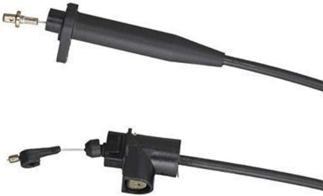
ATP Y-228 TV Detent Cable, GM 700R4 & 200-4R
If the cable binds, kinks, or will not return smoothly through its full travel, it gets replaced — you cannot adjust your way around a dragging cable, and a TV cable that sticks part-way open is what cooks 3-4 clutches and bands. Correct detent cable for 700R4 and 200-4R (2004R) applications.
View on Gearbox Insider →Step 2: Separate "Delayed" From "Slipping"
Delayed engagement and slip feel similar from the driver's seat and mean very different things on the bench. Time it. Pull the lever from Park to Reverse at operating temperature and count, then do the same into Drive, hot and cold.
- Delayed cold, normal hot points at converter or pump drainback and at clearances that close up as parts expand. Fluid drains back overnight, the pump has to refill the converter and circuit before anything applies.
- Delayed hot, better cold is the classic wear signature. Hot fluid is thinner, so it leaks past worn valve bores and bushings faster than the pump can make up for. This is where the pressure regulator circuit gets suspicious.
- Delayed Reverse specifically is its own fault path. Sonnax's 200-4R valve body layout ties delayed Reverse and low Reverse boost directly to the reverse boost valve, with kit K77898 for the large-ratio O-ring style and K77898A for the factory style.
Where the pressure actually goes
On a unit with 100,000-plus miles of unknown history, the pump cover and pressure regulator bore are the usual suspects. Sonnax maps the symptoms cleanly: erratic line pressure, low line rise, clutch slippage, excess pump noise, and 3-4 clutch failure all point to a worn pressure regulator valve bore, addressed with oversized valve 77917-06 (reamed with the 77917-TL tooling). Low base line pressure alone points at the main pressure regulator spring, 77917-08. Erratic pressure that comes and goes can also be the pump spring spacer (77917-RV), and both low and high line pressure show up on the list for a worn pump slide pivot pin (65797).
That last one surprises people. A worn pivot pin lets the slide wander, changing pump output at exactly the wrong moment. On any 200-4R pump you have apart, it is a replace-on-sight item.
Step 3: The Harsh 1-2 Bang at Light Throttle
This is the complaint that walks in most often, and it has a specific home. Sonnax's layout lists "1-2 Bang at light throttle" and "reduced 2-4 band life" together, and both point at the accumulator valve train. There are two versions and they are not interchangeable:
| Valve train | Bore diameter | Application | Sonnax kit |
|---|---|---|---|
| "L" version | .330 in. | Light and medium weight vehicles | 77777L-K |
| "M" version | .341 in. | Heavy weight vehicles | 77777M-K |
Eleven thousandths separates them. Measure the bore before you order, because a G-body and a Cadillac Brougham did not get the same valve train and the wrong kit will not seal. The accumulator valve is what shapes the pressure curve during the 1-2 apply; when its bore wears, the curve steepens and the apply happens as a hit instead of a ramp. That is the bang, and no amount of cable adjustment fixes it.
While the valve body is open, the 3-4 accumulator piston is worth attention too. Sonnax's pinless accumulator piston kit 77998-03K addresses poor shift quality and burnt clutches and bands, but note the restriction: in a 200-4R it can only be used in the 3-4 accumulator location. Installing it elsewhere is a comeback.
Step 4: The Opposite Complaint, and Why It Matters More
Soft, drawn-out shifts feel like a lesser problem to the customer. They are not. A slide shift is a clutch or band slipping while it applies, and it takes life out of the friction material every time. The layout ties soft slide shifts, burned 3-4 clutches, and reduced band life to throttle boost oil leakage at the TV boost valve, and offers a bore-size ladder to fix it:
| TV boost valve kit | Bore diameter | Style |
|---|---|---|
| 77917-02K | .423 in. | Factory style |
| 77917-471 | .471 in. | O-ring style |
| 77917-03K | .471 in. | Factory style |
| 77917-500 | .500 in. | O-ring style, highest boost ratio |
| 77917-04K | .500 in. | Factory style, highest boost ratio |
A worn TV plunger spring (77968-01K) produces the same low throttle pressure and low line pressure signature from a different direction. Check both. If throttle pressure never rises properly, the boost valve never adds line pressure under load, and the unit slips through every part-throttle shift it makes.
One caution: bigger is not automatically better. A larger boost valve changes the rate of pressure rise, which is what you want, but stacking a large-ratio valve onto an already-firm calibration in a light car gives you a transmission that shifts crisply on the highway and slams into Reverse in the driveway.
Step 5: Harshness You Caused Yourself
If the unit was rebuilt recently and came back harsh, look at the separator plate before you look at anything else. Enlarging clutch feed orifices is a legitimate way to firm up a lazy shift, but the math trips people up constantly, because diameter and area are not the same thing. Sonnax's guidance is blunt: a small change in diameter makes a big change in the area the oil flows through, and experience shows a 20% area increase is what gives a noticeable improvement in shift feel without generating harsh-shift complaints.
Some real numbers off their chart, so you can see how tight the window is:
| Original orifice | +20% area | +50% area |
|---|---|---|
| .060 in. | .066 in. | .073 in. |
| .070 in. | .077 in. | .086 in. |
| .090 in. | .099 in. | .110 in. |
Grabbing the next drill index up from a.070 hole and landing at.086 is a 50% area increase, not a mild bump, and that is exactly how a "just a little firmer" build turns into a customer complaining that the car shifts like a forklift. Two 200-4R plate details are worth memorizing while you are in there: 1-2b should always be larger than 1-2a (1-2a is the actual feed orifice), and the 3-4 does not have a conventional feed orifice, so there is nothing to drill there.
Step 6: Friction Surfaces and Fluid
Shift feel is not purely hydraulic. A GEARS Magazine piece from ATRA on friction dynamics includes a 200-4R case worth carrying around: after the band surface of the direct drum was sanded, the sanded surface made the shift so drawn out that it could not complete until the accumulator bottomed out, producing a bump at the end of the shift. A rough surface stretches the shift; a smoother steel or drum surface firms it up. A complaint of "soft, then a bump at the end" is not always a valve, and dressing a drum with abrasive can create a shift quality problem no calibration change will fix.
On fluid, know what changed under you. ATRA's viscosity write-up puts pre-2005 conventional ATF at 6.8 to 8.0 cSt at 100°C and DEXRON VI at 5.8 to 6.4 cSt at 100°C — meaningfully thinner than what a 1980s Hydra-Matic was designed around. Per that same article, GM's position is that transmissions originally filled with DEXRON II or III can now be serviced with DEXRON VI, while Ford, Chrysler and Toyota make no equivalent claim for their older units. DEXRON VI is the correct service fill for a 200-4R. Understand the tradeoff: in a unit with worn bores and a tired pump, thinner fluid leaks past those clearances faster, so marginal hydraulics surface sooner. That is an argument for fixing the bores, not for thicker fluid.
The Order of Operations, Condensed
- Verify wide open throttle at the pedal, then verify the TV cable pulls and returns smoothly.
- Coarse-adjust the cable, road test to 1-2 near 15 mph and 2-3 near 28 mph at light throttle, and confirm the full-throttle 2-1 downshift.
- Check throttle linkage geometry, especially on carb-swapped and engine-swapped cars. Add a corrector kit if the cable pulls out of adjustment at WOT.
- Gauge line pressure at idle in each range and watch the rise as TV is applied. Note hot versus cold behavior.
- Time the Park-to-Drive and Park-to-Reverse engagements hot and cold to separate drainback from wear.
- Vacuum test the pressure regulator, boost valve, TV boost valve, and accumulator bores. Measure the accumulator bore to identify the "L" (.330 in.) or "M" (.341 in.) valve train before ordering.
- Inspect the separator plate for previous drilling, and check that 1-2b is larger than 1-2a.
- Inspect band and drum surfaces for abrasive dressing before blaming the hydraulics.
Work it in that order and most 200-4R shift complaints resolve in the first two steps. The ones that survive to step six are real valve body work, and by then you know which bores to ream instead of guessing at a rebuild.
TV cables, valve body components, pumps, bands, rebuild kits, and the tools to do the job — shipped fast from the USA.
Shop 200-4R parts →Sources
- Sonnax — "GM 200-4R Valve Body Layout," May 10, 2020. Backs the symptom-to-part mapping used throughout: pressure regulator valve bore wear causing erratic line pressure, low line rise, clutch slippage, excess pump noise and 3-4 clutch failure (oversized valve 77917-06, tooling 77917-TL); main pressure regulator spring 77917-08 for low base line pressure; pump slide pivot pin 65797; pump spring spacer 77917-RV; reverse boost valve kits K77898 and K77898A for delayed Reverse and low Reverse boost; the "1-2 bang at light throttle" and reduced 2-4 band life link to accumulator valve train kits 77777L-K (.330 in., light/medium vehicles) and 77777M-K (.341 in., heavy vehicles); pinless accumulator piston kit 77998-03K restricted to the 3-4 location in a 200-4R; TV plunger spring 77968-01K; and the TV boost valve bore ladder 77917-02K, 77917-471, 77917-03K, 77917-500 and 77917-04K for soft slide shifts, burned 3-4 clutches and reduced band life. sonnax.com
- Transmission Digest — "Adjusting Infamous THM700-R4 Throttle Valve Cable," Paul Townsend and Jamie Townsend, November 1, 2018. Backs the five-step TV cable procedure: verifying full throttle with the cable unhooked, checking that the cable pulls and returns smoothly before adjusting, the coarse adjustment sequence, the light-throttle road test targets of roughly 15 mph for the 1-2 and 28 mph for the 2-3, the direction of adjuster changes for early versus late shifts, and the mandatory full-throttle 2-1 downshift verification. transmissiondigest.com
- Sonnax — "TV Cable Corrector Kit AS1-01K." Backs the statement that in most GM and Ford cable-controlled units including the TH200, 200-4R, TH200C, 4L60 (700-R4), AOD and AXOD the TV cable pulls out of adjustment at wide-open throttle, that the cause is throttle shaft lever geometry (degree of pivot movement between closed and wide open throttle, and distance between the attachment element and throttle shaft lever pivot points), and that the corrector kit absorbs excess cable pull with a spring and stop. sonnax.com
- Sonnax — "Drilling Orifices the Smart Way," April 7, 2015. Backs the orifice area guidance: that diameter and area are commonly confused and a small diameter change makes a large area change, that a 20% area increase is the practical target for firmer shifts without harsh-shift complaints, the specific drill dimensions cited (.060 to.066 in. and.073 in.;.070 to.077 in. and.086 in.;.090 to.099 in. and.110 in.), and the 200-4R separator plate notes that 1-2a is the feed orifice with 1-2b always larger, and that the 3-4 has no conventional feed orifice. sonnax.com
- GEARS Magazine (ATRA) — "Friction Dynamics." Backs the 200-4R case in which sanding the band surface of the direct drum drew the shift out so far it could not complete until the accumulator bottomed out, producing a bump at the end of the shift, and the general principle that smoother steel and drum surfaces firm up shifts while rougher surfaces lengthen them. gearsmagazine.com
- GEARS Magazine (ATRA) — "Viscosity and ATF." Backs the fluid viscosity figures of 6.8 to 8.0 cSt at 100°C for pre-2005 conventional ATF versus 5.8 to 6.4 cSt at 100°C for DEXRON VI, and GM's stated position that transmissions originally using DEXRON II or III can now be serviced with DEXRON VI while Ford, Chrysler and Toyota do not make the same claim. gearsmagazine.com