Every shop has had this ticket walk in: a Silverado, Tahoe, Trailblazer SS or GTO with a 4L65E, and the complaint is "it gets hot." The reflex is to sell a bigger cooler. Sometimes that helps. But on this unit a hot transmission is far more often a symptom of a specific hydraulic fault than a cooling-capacity problem, and bolting on a cooler without finding the fault gets you a cooked converter and burnt 3-4 clutches instead of just a high temperature reading.
The 4L65E is the reinforced member of the 4L60-E family — five-pinion planetaries, same case and valve body architecture. That matters, because the parts that generate and mismanage heat here are the same ones that do it in a 4L60-E and 4L70-E, which is why Sonnax documents all three together.
Where the Heat Actually Comes From
Start with the converter, because that is the furnace. Fluid coupling is not free: ATRA's Gears magazine puts torque transfer losses in the roughly 10 percent range during cruise, and that lost energy leaves as heat from fluid shear. Sonnax's Bob Warnke makes the same point hydraulically in Transmission Digest — work creates heat, and circulation is what removes it. A non-lockup converter generates heat any time turbine RPM does not match cover RPM, including on deceleration when the wheels drive the turbine shaft faster than the engine.
Two conclusions follow. Slip is heat, and flow is the only thing that carries it away. Any fault that raises slip, or any fault that cuts flow through the cooler circuit, reaches the scan tool as the same complaint: rising fluid temperature.
The 4L65E Slips On Purpose
Here is the part that catches techs who came up on older units. GM introduced pulse width modulated (PWM) converter clutch control on the 4L60-E in the mid-1990s, adding a second TCC solenoid for a regulated apply valve and changing the lining from paper to high-carbon to survive the extra friction and heat. Under PWM the PCM ramps duty cycle from 0 percent (unlocked) to about 90 percent (full lockup) rather than slamming the clutch on and off.
From 1998 the strategy became EC3, which is what most 4L65E units run, and under EC3 it is generally undesirable to fully lock the clutch. The PCM raises regulator solenoid duty cycle in rapid steps to roughly 50 percent, where the target of 20 to 40 RPM of TCC slip is achieved under most conditions, then trims pulse width to hold it there. Only under high torque or sustained freeway load does it push to about 98 percent for full lock.
So a healthy 4L65E slips its converter clutch on purpose most of the time it is locked, and makes heat on purpose. That makes friction material non-optional: on/off linings burn up under modulated slip, and PWM-era linings wear out early in an EC3 system. If someone installed a converter without a high-thermal-slipping lining, the heat complaint may just be the wrong converter.
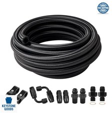
6-Pass Universal Transmission Oil Cooler Kit
Aluminum tube-and-fin cooler with 5/16 in. hose and hardware. Worth adding on tow and plow 4L65E trucks — after you have proven cooler flow is good, not instead of testing it.
See the cooler kit →Cause 1: TCC Regulator and Isolator Bore Wear
This is the number one cause of a hot 4L65E, and it is a wear item by design: the EC3 strategy keeps the TCC regulator valve constantly oscillating in an aluminum valve body casting, and that oscillation wears the bore. Per Sonnax, in GM 4L60-E, 4L65-E and 4L70-E units severe wear of the TCC regulator valve bore caused by valve oscillation allows regulated converter apply pressure to exhaust — described as a primary cause of TCC slip code P1870 and overheated converters. Wear at the isolator end of the same bore reduces apply pressure the same way.
Follow the chain: apply pressure bleeds off, clamping force drops, slip runs well past the 20–40 RPM target, and the converter cooks. Worse, the exhausting apply pressure also diminishes line pressure, which is why these units so often arrive with burnt clutches on top of a fried converter.
The Diagnostic Tell Nobody Uses
You do not need the transmission out to catch this. Because the PCM is closed-loop on slip, it compensates for a leaking bore by raising duty cycle. Sonnax calls this out directly: as the regulator bore wears, the duty cycle needed to keep slip in range increases, so you can spot the problem before it sets a code. Their example — a low-mileage vehicle running an average TCC duty cycle around 79 percent — is a PCM already compensating for circuit wear, most likely in that bore. Log TCC PWM duty cycle on a steady 55–65 mph cruise against TCC slip RPM. Normal EC3 cruise sits near 50 percent with slip inside 20–40 RPM.
The Fix
Ream the bore and install Sonnax TCC regulator and isolator valve kit 77754-04K (OE apply rate; 77754-03K for an increased rate), which restores the regulator section with a wear-resistant aluminum sleeve and hardcoat anodized valve. One caution from Sonnax's own follow-up: the kit's lengthened isolator valve is meant to run in an unworn portion of the bore, but high-mileage cores are often worn at that end too. Vacuum test it, and if the isolator section is worn, oversize it with reamer 77754-RM5 (or tool kit F-77754-TL4) and fit isolator sleeve kit 77754-ISO.
Cause 2: TCC Apply Valve Wear in the Pump Cover
The second valve worth suspecting lives in the pump cover, not the valve body. Excess bore-to-valve clearance there lets TCC signal oil leak past the spool, so the clutch either never applies or drops out once the fluid warms and thins. Converter feed oil can also leak past, combine with orificed signal oil, and exceed what the solenoid can exhaust — stroking the valve fully into lockup.
The case that matters most for a heat ticket is the middle one. Sonnax describes cross-leaks floating the valve into a mid-way position, which restricts cooler flow and burns up the converter. Nothing is wrong with the cooler, the lines or the fluid. The valve is simply parked where it strangles the circuit that carries heat out.
Symptom set from the Sonnax vacuum test guide for this unit: no lockup, falls out of lockup when hot, code 1870, or lockup immediately after the 2-3 shift. The repair is TCC apply valve kit 77805E-K for PWM units or 77805-K for non-PWM, and this is one you must not get wrong — Sonnax states plainly that mismatching PWM and non-PWM valves causes rapid converter failure. Check pump design too: the early pump uses a 1.907 in. sleeve, the late pump a 1.890 in. sleeve, and boost valve options differ accordingly.
Cause 3: The Cooler Circuit Itself
Only after clearing the two valves above does the cooler itself deserve attention, and then you need to know what the control valve is doing. Sonnax describes the thermal type as a wax-filled element that positions a pin: pin-in is the cold position, sending converter oil to the front pump bushing and lube circuit, and pin-out is the hot position, moving the cooler control valve so converter oil goes to the radiator cooler. Warm-up flow is routed to lube until fluid reaches roughly 130°F, with specific elements typically stroking out at 125°F or 135°F.
If that pin does not extend, extends only partway, or extends and retracts to mid-point, converter outflow is restricted or routed internally and never reaches the cooler — producing an overheated converter, temperature codes, and affected clutch apply. Qualify a suspect element on the bench: drop it in a slow cooker with ATF and a separate thermometer, verify the pin fully extends at temperature, and check both extended pin length and its resistance when pushed back in. A pin that extends fully but pushes in easily is a partial-stroke failure waiting to happen.
One Practical Warning About Fluid Level
This one bites shops constantly. If the thermal valve never opens during your road test, the cooler circuit is never charged, so you set level with fluid still in the transmission that belongs in the cooler and lines. The vehicle comes back low. Get the unit to full operating temperature before you set level and before you release the car.
Cause 4: A Blocked TCC Regulator Valve (Self-Inflicted)
If you buy used 4L65E cores or take in other shops' work, look for this before you diagnose anything else. Builders learned years ago that they could make P1870 and P0894 disappear by blocking the TCC regulator valve with an inner pump slide spring from a 700-R4, reverting the circuit to on/off. The codes go away. The bore wear that caused them does not.
What the modification actually does is dump full line pressure into the apply circuit — up to 140 psi under load, against OE apply pressures of roughly 60 to 80 psi. Sonnax's consequence list reads like a converter failure report: cracked or deformed TCC pistons, broken damper rivets, torsional driveline disturbance, damaged crankshaft bearings, harsh apply, lining delamination, converter failure. It also opens the worn bore straight to line pressure, adding a sizeable leak on top. If a customer wants more clamping force for towing, use Sonnax's TCC pressure limiter spring instead, which caps apply pressure near 100 psi (about 110 psi paired with 77754-03K).
Diagnosing It on the Vehicle: The Order That Works
Do these in sequence. Each step tells you which half of the system to stop looking at.
| Step | What to watch | What it tells you |
|---|---|---|
| 1. Scan data, steady cruise | TFT, TCC slip RPM, TCC PWM duty cycle %, commanded vs. actual gear | Slip outside 20–40 RPM, or duty cycle high (near 79%+) to hold it there, points at regulator bore wear |
| 2. Codes | P1870, P0894 | Excess TCC slip. Neither says where the leak is — go to steps 3 and 4 |
| 3. Flow meter on the cooler line | Flow change when TCC is commanded; release flow below 0.45 GPM | Below 0.45 GPM the piston starts dragging on the cover. A momentary drop then a new settled level proves the control valve stroked |
| 4. Loop the cooler lines, retest | Does the condition disappear? | Gone = restriction in the cooler or lines. Still there = restriction before the piston, inside or outside the converter |
| 5. Line pressure gauge with the flow meter | Pressure and flow together | Low pressure + low flow = pump circuit wear. High pressure + low flow = PR valve stroked out of balance |
| 6. Vacuum test valve body and pump cover | TCC regulator valve, TCC apply valve, PR/boost valve | Low vacuum = bore wear. Confirm 77754-04K / 77754-ISO / 77805E-K here before ordering |
Two notes on that table. Scan tool temperature comes from the valve body thermistor, and converter-out temperature is always higher; if the reading keeps climbing rather than plateauing, Sonnax's guidance is that you have either excessive converter slip or insufficient cooler flow. And a clean cooler-loop test does not convict the converter: the TCC exhaust passage runs through the turbine shaft, pump, case and valve body and can be up to 13 inches long, so a restriction anywhere along it mimics weak apply pressure.
Prevention: What Actually Keeps a 4L65E Cool
- Flush and prove the cooler after any converter or clutch failure. Debris loads the cooler, and every hot-running comeback after that traces back to it. Prove flow with a meter, not by eyeballing a stream into a bucket.
- Match the TCC lining to the control strategy. EC3 units need a high-thermal-slipping lining. An on/off lining burns; a PWM lining wears out early.
- Do not block the regulator valve. Sleeve the bore instead, and use the pressure limiter if the customer wants more clamp.
- Set fluid level hot, after the thermal valve has opened. Cold-set levels come back low, and low fluid is its own heat source.
- Use DEXRON-VI and only DEXRON-VI. ATRA's technical staff are blunt about substitution: converter friction material and OEM programming were validated together, and variation in viscosity or additive package produces shudder and apply problems.
- Add cooling capacity for the duty cycle, not for the diagnosis. Trucks that tow, plow or idle in traffic benefit from an auxiliary cooler. A truck with a worn regulator bore needs the bore fixed.
- Watch duty cycle at every service. Two minutes of logging catches regulator bore wear years before it takes the converter and the 3-4 pack with it.
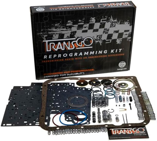
Valve body kits, TCC components, coolers and cooler line kits, overhaul kits and solenoids — shipped fast from the USA.
Shop 4L65E parts →The Short Version
A hot 4L65E is slipping more than it should, or not moving fluid through the cooler. Two worn bores — the TCC regulator/isolator in the valve body and the TCC apply valve in the pump cover — account for most of what pushes a normal 20 to 40 RPM of slip into converter-killing territory. Log duty cycle and slip, put a flow meter on it, loop the cooler lines, then vacuum test. Sell the cooler last, not first.
Sources
- Sonnax — TCC Regulator & Isolator Valve Kit 77754-04K. Backs the core mechanism: in GM 4L60-E, 4L65-E and 4L70-E units, severe TCC regulator valve bore wear from valve oscillation allows regulated converter apply pressure to exhaust, a primary cause of code P1870 and overheated converters; exhausting apply pressure also diminishes line pressure and results in burnt clutches, and isolator bore wear reduces TCC apply pressure. sonnax.com
- Sonnax — "20 Years Later: What's New with 4L60-E PWM Modifications." Backs the PWM and EC3 control detail: second TCC solenoid and lining change, 0–90% PWM duty cycle ramp, EC3 target of 20–40 RPM slip at roughly 50% duty cycle rising to 98% under high load, rising duty cycle (the 79% example) as an early tell of regulator bore wear, OE apply pressure of about 60–80 psi versus up to 140 psi with the valve blocked by a 700-R4 inner pump slide spring, the resulting converter damage list, the 100 psi / 110 psi pressure limiter figures, and HTE versus HTS friction lining selection. sonnax.com
- Sonnax — "Understanding Cooler Control Valves: What Thermal vs. Pressure Control Means for Your Build." Backs the cooler circuit section: thermal element pin-in (lube) versus pin-out (radiator cooler) operation, the roughly 130°F opening point and typical 125°F/135°F pin-out specs, converter overheat and temperature codes when the pin does not fully extend, the slow-cooker bench test for qualifying an element, the warning that an unopened thermal valve leaves the cooler circuit uncharged and the vehicle low on fluid, the fact that converter-out temperature exceeds the valve body thermistor reading, and the guidance that a continually rising scan tool temperature indicates excessive converter slip or insufficient cooler flow. sonnax.com
- Sonnax — TCC Apply Valve Kit 77805E-K. Backs the pump cover failure mode: excess bore-to-valve clearance letting TCC signal oil leak past the spool causing no lockup or hot dropout, converter feed combining with signal oil to fully stroke the valve, cross-leaks floating the valve mid-way to restrict cooler flow and burn up the converter, and the warning that mismatching PWM and non-PWM valves causes rapid converter failure. sonnax.com
- Sonnax — "Troubleshooting Lockup Issues," Ed Lee. Backs the on-vehicle diagnostic sequence: using a flow meter to confirm the TCC control valve strokes, the 0.45 GPM TCC release flow threshold below which the piston drags on the cover, the cooler-line looping test to isolate restrictions before versus after the TCC piston, reading line pressure and flow together to separate pump wear from a PR valve stroked out of balance, and the TCC exhaust passage running up to 13 in. through the turbine shaft, pump, case and valve body. sonnax.com
- Transmission Digest — "Hydraulics Fundamentals: Converter Clutch Control Part 1," Bob Warnke (Sonnax VP of technical development, ATRA/TASC Force). Backs the heat-generation fundamentals: internal pressure and fluid movement perform the work, work creates heat so circulation is required to remove it, a non-lockup converter generates heat whenever turbine RPM is not matched to cover RPM including during deceleration, and low converter charge pressure produces high stall, low power and turbine damage. transmissiondigest.com
- Gears Magazine (ATRA) — "Lock Up Madness! GM and Ford Torque Converter Clutch Control." Backs the roughly 10 percent torque transfer loss converted to heat by fluid shear in cruise, and the warning against fluid substitution because converter friction material, surfaces and OEM programming are validated together so viscosity or additive variation produces shudder and TCC apply/release problems. gearsmagazine.com