A 4L65E that slams into gear, drops out of overdrive at the same road speed every time, or shows a dead speedometer is usually not a clutch problem. It is a speed signal problem. The module decides shift timing, line pressure and converter clutch apply by comparing what goes into the transmission against what comes out of it, and when either number goes away or goes noisy, the strategy defaults to something safe and ugly.
What trips most techs up is that a 4L65E has two completely different sensor setups depending on when the unit was built, and on 4WD trucks the sensor you are chasing may not be on the transmission at all.
Which Speed Sensors Does Your 4L65E Actually Have?
The 4L65E is the reinforced 4L60-E and inherited the family's sensor history. Early units have one transmission speed sensor. Later units have two.
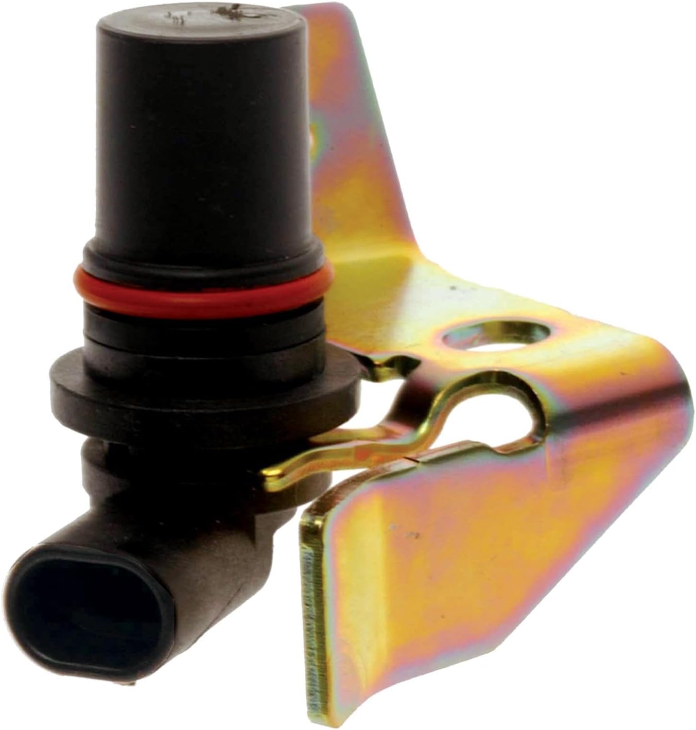
Output side, all years. The vehicle speed sensor, which service data also calls the output shaft speed sensor, is a two-wire permanent magnet generator in the case or extension housing, aimed at a reluctor (exciter) pressed onto the output shaft. As the teeth sweep past the magnet, the coil generates its own AC voltage. Nothing powers it. Voltage and frequency both climb with shaft speed, which is why a scope beats a meter here.
Input side, later units only. The input speed sensor bolts to the stator support inside the pump and reads the input shaft. Sonnax dates the changeover to between February 2005 and early 2006, and it was not just a new sensor: to make room, GM moved the charge oil and converter clutch release passage in the pump cover and stator support. Covers and stator supports now have to be matched or you block the feed, the early non-ISS stator support carries a different part number than the late ISS-compatible one, and there is a transition pump with the boss cast in place but no hole drilled. So a 2004 truck with a P0716 in memory is not reporting a bad input sensor. It is reporting that somebody swapped a module, a harness or a calibration.
4WD trucks, the third case. On four-wheel-drive applications the road speed signal can come from a sensor in the transfer case. GM bulletin PIP4966B covers 2007-2011 Silverado, Suburban, Tahoe, Avalanche, Sierra and Yukon with Magna transfer cases under RPO NP0, NQF, NQG and NQH, and the fault is mechanical: the tone wheel moves on the output shaft, or the output shaft itself moves.
The Codes and What Each One Is Really Saying
| Code | Definition | What it usually means on a 4L65E |
|---|---|---|
| P0716 | Input speed sensor performance | Signal present but disagrees with engine speed and ratio. Chafed wiring, loose connector, ground problem. |
| P0717 | Input speed sensor circuit low voltage | Signal gone. Open circuit, failed sensor, or a lost ground inside the module. |
| P0721 | Output speed sensor performance | Noisy or implausible output. Air gap, reluctor damage, sensor orientation. |
| P0722 | Output speed sensor circuit no signal | Dead circuit. Wiring, sensor, or on 4WD a transfer case tone wheel that walked. |
| P0723 | Output speed sensor circuit intermittent | Dropping in and out. Sets with a normal-looking meter reading. |
| P0730 / P0731-P0734 | Incorrect gear ratio | Usually downstream, not a separate fault. The module is doing ISS-versus-OSS math with one bad number. |
Do not treat a ratio code next to a speed sensor code as two problems. Fix the speed signal first and recheck.
What It Feels Like From the Driver's Seat
- Harsh shifts with a history code and no current fault. GM's bulletin PIP5084A opens with exactly that complaint: a harsh shift or illuminated MIL, with P0716 or P0717 found as a history code in the TCM. The module saw the signal drop, raised line pressure to protect the clutches, and by the time the truck is on your lift only the shift quality complaint is left.
- A downshift at a repeatable road speed. A documented Transmission Digest case on a 4L60-E drivetrain ran flawlessly until roughly 35 mph, then dropped from fourth to third and sometimes to second, with output speed and vehicle speed data both fluctuating when it happened.
- Speedometer dead, erratic, or lagging. The cluster is fed from the same output signal, so an air gap problem often shows on the dash before the transmission complains.
- Stuck in one gear, or a converter clutch that will not apply. Both are scheduled off speed and ratio. Take away an input and the module falls back to a default.
- ABS or stability warnings alongside the transmission complaint. On the 4WD trucks in PIP4966B, the same tone wheel problem can store C0055 for rear wheel speed sensors in the brake module or P2771 for the four-wheel-drive low switch circuit in the engine control module.
Testing the Input Speed Sensor Circuit the Way GM Does
This is where most shops replace a sensor that was fine. Per GM bulletin PIP5084A, issued January 2013 for 2013 Express, Silverado, Savana and Sierra with the 4L60E (RPO M30), the additional diagnosis for P0716 and P0717 is a ground test, not a sensor test:
- Check circuit 1984 from the input speed sensor at terminal V to the transmission control module at terminal 45.
- Install the J 44152 twenty-pin breakout harness on the engine side of the transmission inline 20-way connector.
- With a test light, go from terminal E to terminal V to check the TCM ground. If the test light does not light, the internal ground in the TCM is suspect.
- Unplug the TCM connector and check for continuity across pins 45 and 49. No continuity means replace the TCM and the ISS. Continuity present means replace the ISS only.
The parts listed are input speed sensor 24244544 and TCM 24252114, labor operations K6311 and K5365. Transmission Digest describes the same loss-of-ground failure and a field repair for it: splice into circuit 1984/1231 and provide an external ground, since that circuit runs from TCM terminal 45 to terminal V at the case connector. Run the ground test before you order anything, because a TCM with a failed internal ground will eat a new sensor's worth of labor and set the code right back.
The Post-Rebuild ISS Failure Nobody Warns You About
If the unit was just overhauled and came back with P0716 or P0717, look inside before you look at the harness outside. Transmission Digest documents the cause directly: the input speed sensor wiring was not properly secured in its locating brackets on the back of the pump assembly, and the wires were then damaged by the spinning reverse input drum, which passes close to that wiring. That is a comeback you create on the bench. Route the ISS lead through both brackets and confirm it is captured before the pump bolts go in.
4L65E Input Speed Sensor, GM 24244544
The exact GM part number called out in bulletin PIP5084A for the input speed sensor replacement. Fits 2001-2013 4L65E applications. Sold by our sister store.
See the 4L65E input speed sensor →Chasing the output side instead? There is a matching 4L65E output speed sensor, or browse the full 4L65E parts collection.
Scoping the Output Speed Sensor: Amplitude Is the Tell
Because the output sensor generates its own AC voltage, a resistance check tells you almost nothing. A coil can read in range and still produce a signal too weak for the module. Put a scope on it.
The Transmission Digest case above shows what to look for. Back-probing the module at the vehicle speed sensor inputs, the technicians had to drop the scope to a 5V scale to see the wave at all when they normally set it to a 100V scale, and the wave oscillated while driving. Two modules and two sensors had already been installed and neither fixed it. The fault was orientation: the sensor had been rotated roughly 90 degrees in a modified bracket so it pointed toward the front of the vehicle instead of down toward the road, where a factory 4L60-E family sensor aims. With the magnetic poles no longer aligned with the exciter, the lines of flux were wrong and the output collapsed. Rotating it back stopped the oscillation and brought the signal to 34 volts peak to peak.
So amplitude on a healthy permanent magnet sensor is large, tens of volts at road speed, not a couple. Any time you find one in a non-factory bracket or after someone has been in the extension housing, confirm the aim before condemning anything electrical. The rest of the checklist:
- Inspect the sensor tip for a magnet packed with steel fuzz. The fuzz alone kills the signal, and it tells you something upstream is wearing.
- Inspect the reluctor teeth for chips, cracks and a loose press fit. A damaged tooth shows as a repeatable notch in the wave, not as a code.
- Check the connector for green terminals and backed-out pins, and look for wiring against hot exhaust, a rotating shaft, or a butt-connector splice.
Doing the Ratio Math on a Scan Tool
The fastest way to decide which sensor is lying is to make the module's own math visible. Graph input speed, output speed and commanded gear together on a road test with the fluid at operating temperature. The 4L65E runs the 4L60-E family ratios: 3.06 first, 1.63 second, 1.00 third, 0.70 overdrive. Divide input speed by output speed and you should land on the ratio for the commanded gear, within a little slip. Deviations point somewhere specific:
- Input speed drops out while output speed stays clean and engine speed is normal: input circuit.
- Output speed drops out or spikes while input speed tracks engine speed: output circuit, or the transfer case tone wheel on a 4WD truck.
- Input speed will not follow engine speed with the converter clutch fully applied: input signal, since locked those two should track closely.
- Both read cleanly and the ratio still does not match the commanded gear: that is real slip. Now you are looking at clutches, band, servo or pressure.
Record the drive. The intermittent codes, P0723 especially, rarely reproduce on the lift.
Speed sensors, internal wiring harnesses, solenoid kits, valve bodies and overhaul kits for the 4L65E — shipped fast from the USA.
Shop 4L65E parts →The 4WD Trap: Check the Transfer Case Before the Transmission
If the truck is a 2007-2011 GM full-size 4WD with an intermittent speedometer, an ABS message, or speed-related codes that standard diagnostics will not pin down, GM's PIP4966B tells you where to look. Excess movement of the tone wheel or the output shaft changes the air gap to the vehicle speed sensor and can cause an erratic signal or a complete loss of signal.
The inspection is straightforward. Remove the propeller shaft and look up the output shaft past the rear seal to confirm the snap ring is present and seated in its groove. The bulletin points to the illustration for each case: document 1824278 items 29 and 28 for NQH, document 2372510 items 36 and 35 for NQF, and document 2372500 items 34 and 33 for NQG. GM notes the tone wheel normally has about 1/8 inch (0.125 in., 3.175 mm) of movement on the output shaft, but it must stay centered in the sensor opening. That is the useful part: a tone wheel that slides and recenters is normal, one that has walked out of the sensor window is your fault, and no transmission sensor will fix it.
Keeping It Fixed
- Secure the ISS lead in both pump brackets on every rebuild, then verify by feel before the pump goes down.
- Match the pump cover and stator support. Sonnax's three identification checks exist because mixing ISS and non-ISS parts blocks the relocated charge oil passage, and that failure is much more expensive than a sensor code.
- Never rotate the output sensor in its bracket to reach a short harness. Fix the harness length instead.
- Solder and heat shrink speed circuits, not crimp caps. These are low-current signal lines where a slightly resistive joint becomes an intermittent code.
- Clear history and road test. A history-only P0716 or P0717 with a harsh shift complaint is a fault that already happened, so verify with a drive, not an ignition cycle.
FAQ
Can you drive a 4L65E with a bad speed sensor?
It will usually still move, but not far. With a lost or noisy speed signal the module commands high line pressure and a default shift pattern, which means very harsh engagements. GM's PIP5084A lists the harsh shift complaint alongside P0716 and P0717 for exactly that reason, and repeated hard shifts damage the clutches and the band.
Does a 4L65E have an input speed sensor?
Only later units do. Sonnax dates the changeover in the 4L60-E family to roughly February 2005 through early 2006, and adding the sensor required relocating the charge oil and converter clutch release passage in the pump cover and stator support. Earlier units use the output sensor alone. Confirm by looking for the sensor hole in the pump cover rather than going by model year, because transition pumps have the boss cast but no hole drilled.
What is the difference between P0716 and P0717?
P0716 is a performance code: the signal is present but does not agree with the module's other data. P0717 is a circuit low voltage code: the signal is effectively gone. Both point to the same circuit, and per PIP5084A the additional diagnosis for both starts with circuit 1984 and the TCM ground, not the sensor.
How do you test a 4L65E output speed sensor?
Use a scope, not an ohmmeter. It is a permanent magnet generator that makes its own AC voltage, so amplitude is the tell. A Transmission Digest case measured 34 volts peak to peak at road speed once a misaligned sensor was corrected, with the scope normally set at a 100V scale. A wave you can only see on a 5V scale is weak, and the cause is usually air gap, orientation or the reluctor rather than the sensor.
Why does my speedometer work but the transmission still shifts wrong?
On a later 4L65E the module has two speed inputs. The output side can be perfectly healthy, keeping the speedometer accurate, while the input side drops out and ruins the ratio math used to schedule shifts and converter clutch apply. That combination points straight at the input circuit. Graph input speed against engine speed with the converter clutch applied and the dropout becomes obvious.
The Short Version
Identify which sensors the unit actually has first, because a 2004 4L65E and a 2008 4L65E are not the same electrical animal. On the input side, test the ground the way GM's bulletin does before buying a sensor, and secure that wiring on the pump during a rebuild. On the output side, scope for amplitude and confirm the sensor is aimed where the factory aimed it. On a 4WD truck, check the transfer case tone wheel first. Most of these jobs are a wiring, ground or air gap repair wearing a sensor code.
Sources
- General Motors — Bulletin PIP5084A, "Harsh Shift Illuminated MIL DTC P0716 And Or P0717 May Be Current Or In History In The TCM," January 2013 (hosted by NHTSA). Backs the harsh-shift-with-history-code complaint and the full diagnostic sequence: check circuit 1984 from ISS terminal V to TCM terminal 45, install the J 44152 twenty-pin breakout harness on the engine side of the inline 20-way connector, test light from terminal E to terminal V to check TCM ground, continuity across TCM pins 45 and 49 to decide between replacing the ISS alone or the ISS and TCM, plus parts 24244544 and 24252114 and labor operations K6311 and K5365. static.nhtsa.gov
- General Motors — Bulletin PIP4966B, June 2013 (hosted by NHTSA). Backs the 4WD transfer case section: 2007-2011 Silverado, Suburban, Tahoe, Avalanche, Sierra and Yukon with Magna transfer cases NP0, NQF, NQG or NQH; erratic or inoperative speedometer with C0055 or P2771 stored; tone wheel or output shaft movement changing the air gap to the vehicle speed sensor; the snap ring inspection via the propeller shaft with document IDs 1824278, 2372510 and 2372500; and the roughly 1/8 inch (0.125 in., 3.175 mm) of normal tone wheel movement that must stay centered in the sensor opening. static.nhtsa.gov
- Transmission Digest — "GM 4L70-E ISS DTC P0716 or P0717," October 2020. Backs the post-rebuild failure and the ground repair: input speed sensor wiring not properly secured in its locating brackets on the back of the pump assembly and then damaged by the spinning reverse input drum, and the loss of ISS ground inside the TCM that can be repaired by splicing into circuit 1984/1231 for an external ground, the circuit running from TCM terminal 45 to terminal V at the case connector. transmissiondigest.com
- Transmission Digest — Jesse Zacarias and Roy Delfran, "Wave Forms Provide Key to Diagnosis," October 2010. Backs the scope diagnosis: a 4L60-E drivetrain that downshifted from fourth at about 35 mph with fluctuating output speed and vehicle speed data, a wave form only visible on a 5V scale when a 100V scale is normal, the sensor found rotated to point toward the front of the vehicle instead of down toward the road so the magnetic poles were misaligned with the exciter, and a corrected signal of 34 volts peak to peak. transmissiondigest.com
- Sonnax — "4L60-E: No Move After Rebuild." Backs the ISS changeover and the pump consequence: the transition from non-ISS to ISS-equipped units running from February 2005 into early 2006, the charge oil and converter clutch release passage relocated in the pump cover and stator support to make room for the input speed sensor, the early versus late stator support part numbers, and the transition pump that has the boss cast in place but no sensor hole drilled. sonnax.com
- Sonnax — "4L60-E Series Input Shaft, Stator & Pump Cover Compatibility: Three Easy Checks." Backs the prevention advice on matching components: identifying shaft type and whether the pump cover has the ISS hole drilled, identifying early versus late pump style by where the converter feed hole sits relative to a line through the pump bolt holes, and identifying early versus late stator style by the relationship between the converter feed and lube holes. sonnax.com