P0742 reads out as Torque Converter Clutch Circuit Stuck On, and the word "circuit" in that description has cost the industry a lot of good solenoids. On a 4L80E this code is not a circuit test. It is a slip test: the module compares engine speed to turbine speed while it has the clutch commanded off, and if those two numbers refuse to separate, it writes the code.
That changes the whole job. A circuit fault you find with a meter. A slip fault means something is holding the clutch against the cover, and on this unit there are four places that can happen, only one of which is electrical.
Related reading: our 4L80E P1870 slip code writeup and the 4L80E TCC shudder diagnosis, which share this circuit from the other direction.

Exactly what has to happen before the code sets
GM publishes the enable criteria for this unit, and reading them carefully saves a road test. Per GM's 4L80E Transmission Diagnostic Parameters, P0742 detects low torque converter slip when the TCC is commanded off. Every one of these has to be true at once:
- TCC slip stays between -15 and +15 RPM.
- Engine running above 400 RPM for more than 7 seconds, speed between 800 and 4400 RPM.
- System voltage above 8 and below 18 volts for more than 0.5 seconds.
- Commanded gear not 1st, range selector indicating D4, speed ratio between 0.95 and 2.18.
- Throttle above 12 percent, engine torque above 125 lb-ft.
- Vehicle speed between 7 and 75 MPH.
- Transmission fluid temperature between 20 and 130 degrees C.
- No ISS, VSS, PSA, TPS or MAP codes, no TCC Stuck Off code, no TCC PWM electrical code, no component slipping code.
- All of it held for 3.0 seconds, on the fourth occurrence. Type B.
Three things fall out of that list immediately.
First, this is a 2nd and 3rd gear test. A speed ratio window of 0.95 to 2.18 brackets the 1.48 and 1.00 ratios and excludes 4th at 0.75. GM says as much in the companion code: P0741 monitors excessive slip in 2nd and 3rd only, because 4th gear slip is handled by P1870. The stuck-on test lives in the same window.
Second, the code and the classic complaint do not overlap. Everybody pictures a stuck converter clutch as a truck that dies coming up to a stop sign, but this monitor wants 7 MPH minimum, 12 percent throttle minimum, and a commanded gear above 1st. A clutch that hangs on for the last hundred feet of a coast-down is outside the window, so the module never looks. You can have a truck that stalls at every light and stores nothing, and P0742 stored on a truck that has never stalled once.
Third: P0742 will not set if a TCC PWM electrical code is already stored. The module refuses to run a hydraulic-behavior test on a circuit it already knows is broken. So P0742 standing alone means the solenoid's electrical side passed its own test. Not proof the solenoid is mechanically good, but it moves the wiring down the list.
How the 4L80E actually applies the converter clutch
You cannot diagnose a stuck-on clutch without knowing what is supposed to move. The 4L80E uses one TCC PWM solenoid controlling three valves, which is a later and more integrated design than the enable-plus-PWM two-solenoid setup in a 4L60E. Sonnax's TASC Force writeup on GM converter clutch circuits lays out the sequence, and notes the 4L80E is hydraulically near-identical to the 4T80-E.
The solenoid duty-cycles 3rd clutch oil into TCC control pressure. That pressure operates, in order:
- TCC enable valve. With the clutch released, this valve routes feed limit pressure to the spring side of the apply valve. That is deliberate: it keeps the apply valve from hunting back and forth on a pulsed signal. As duty cycle climbs, the enable valve strokes first and exhausts that feed limit pressure.
- Converter clutch control (apply) valve. With its spring side now exhausted, this valve strokes and redirects converter release oil to the enable valve for an orificed exhaust.
- Converter clutch regulator valve. Pulsed TCC control pressure positions this valve, which regulates line pressure into apply pressure and sends it to the converter for a controlled slip engagement.
A fourth valve, the converter feed limit valve, caps release pressure. On the 4L80E that ceiling is 93 to 107 psi.
Now the sentence that explains this code. Sonnax flags a specific weakness in this architecture: if the apply valve sticks in the on position, there is no release pressure to the converter at all, and the converter overheats. That is your P0742 in hydraulic form. The clutch is not being commanded on. It is being held on because the oil that is supposed to push the piston off the cover has nowhere to come from.
The bench detail nobody mentions: most of this is in the pump
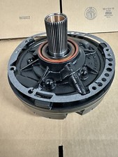
This is where a lot of 4L80E TCC diagnosis goes sideways. On a 4L60E you drop the pan and the TCC valves are right there. On a 4L80E they are not. Sonnax's exploded views for the unit put the converter limit valve, TCC enable valve, pressure regulator valve and TCC valve in the pump. The valve body holds the shift valves, manual valve, actuator feed limit valve, accumulator control valve, and exactly one TCC valve: the TCC regulator valve.
So a pan-down repair gets you the solenoid and the TCC regulator valve. It does not get you the apply valve or the enable valve. If the diagnosis points at those, the unit comes out and the pump comes off. Knowing that before you quote the job is the difference between a profitable ticket and an apology.
Symptoms worth writing on the ticket
- Engine stalls or is dragged down toward stall on deceleration to a stop, especially in gear with the brake applied.
- Engine will not idle normally in a drive range; roughness that clears the instant you select Neutral.
- Overheated converter and transmission temperature running high with no obvious cooler restriction.
- Chatter or shudder that gets worse as the fluid heats.
- Burnt fluid smell with no clutch material in the pan, because the material that burned is inside the converter.
One piece of history worth carrying: Ed Lee, writing for Transmission Digest, points out that the 4L80E did not have an engine stall complaint for years. It started when the unit was mated to a small diesel in one-ton utility vehicles, because the earlier engines simply idled higher. A clutch that drags slightly is survivable behind a high idle and fatal behind a low one, so on a low-idle application the amount of drag needed to produce a complaint is much smaller than your instincts suggest.
Diagnosing it in order
1. Fluid level and condition, before anything else
Low fluid starves the converter feed circuit, and burnt fluid varnishes valves into their bores. Check level hot and in gear per the procedure, and look at the fluid on a white rag. If it is brown and smells cooked, the converter is already a replacement, not a diagnosis.
2. Clear the electrical side properly
The module hinted at this by letting P0742 set at all, but verify the shared feed. ATRA's GEARS writeup on solenoid circuit testing makes the point that matters: never use a testlight on a computer-controlled solenoid circuit. A testlight glows at eight volts or less, well below what a solenoid needs to work, so it will happily call a marginal circuit good. Use a voltmeter. One ignition-fed circuit supplies the TCC, TCC PWM and shift solenoids, and many modules stop checking other circuits once a single solenoid code sets, so one stored code is not proof the feed is healthy.
3. Watch the right PIDs on a road test
Graph TCC Slip RPM, TCC PWM duty cycle, commanded gear, TPS and TFT together. You are looking for slip collapsing to near zero while the duty cycle command sits at zero. If duty cycle is commanded up and slip goes to zero, the system is working and the complaint is elsewhere. Zero duty cycle with zero slip confirms the code's own criteria on your screen, and puts the fault downstream of the command.
4. Put a flow meter on it
This is the step that separates a real diagnosis from a parts swap. Ed Lee's number is the one to remember: when converter release flow drops below 0.45 GPM, the TCC piston starts dragging on the cover. Below that, the condition worsens with every tenth of a gallon.
Then loop the cooler lines to bypass the cooler entirely. If the drag goes away with the lines looped, the restriction is after the piston and lives in the cooler or the lines. If the condition is still there, the restriction is before the piston, inside the transmission or inside the converter.
5. Read line pressure and flow at the same time
Two gauges beat one. With a line pressure gauge installed alongside the flow meter:
- Low pressure with low flow means wear in the pump or the pump circuit.
- High pressure with low flow means the pressure regulator valve is stroked out of balance. Since the PR valve is a demand valve, high pressure, low output, or both together will cut release oil.
Sonnax's vacuum test guide lists low TCC release pressure and low cooler flow as documented symptoms of a worn pressure regulator valve bore on this unit, which is exactly the failure mode the two-gauge test isolates.
6. Prove the converter itself
Block the TCC control valve in the apply position. If the engine stalls in any drive range, the converter is fine and the problem is outside it. If it does not stall, do not condemn the converter yet: a leak anywhere between the control valve and the converter reads the same, whether it is a damaged input shaft seal, worn sealing rings at the stator end of the shaft, or worn shaft-to-stator bushings.
7. Vacuum test the bores on the bench
Once the unit is apart, vacuum testing tells you which bore is leaking instead of which part is cheapest. Per Sonnax's 4L80E vacuum test guide:
- TCC regulator valve (valve body): a low reading here backs TCC codes, apply and release concerns, converter shudder and burnt converters. Repaired with kit 34994-01K, or 34994-18K oversized if the bore is too far gone for a drop-in.
- TCC valve and TCC enable valve (pump): tested through the TCC signal circuit with O-ringed end plugs 34994-13 (.497 in.) and 34994-14K (.668 in.). Low readings here go with no converter apply and burnt converter lining.
- Pressure regulator valve (pump): harsh or soft shifts, engine surge at idle, burnt clutches, low TCC release pressure, low cooler flow.
- Converter limit valve (pump): excessive converter pressure and harsh TCC apply. Seal the indicated orifice when testing this one.
The fix, in the order it usually lands
- TCC PWM solenoid. Debris in the fluid is the common reason one hangs. If the fluid was dirty enough to stick a solenoid, the filter and a full service go with it, not as an upsell but because the same debris is still in there.
- TCC regulator valve bore. Sonnax's own description of the failure is loss of crucial apply pressure through a worn regulator bore, and the drop-in kit uses a hardcoat anodized aluminum valve with a lengthened spool and annular grooves to fight the side loading that wore the original. The kit ships two selective springs, one for OE lockup feel and one firmer than OE.
- Apply valve and enable valve in the pump. The unit comes out for this. It is also the repair that matches the "no release pressure at all" description most exactly, so if the truck is stalling hard and consistently, do not spend two visits avoiding it.
- The converter. If the clutch has been dragging long enough to cook the lining, no valve work saves it. Replace it, and flush or replace the cooler so the debris you just liberated does not come straight back.
Need the part for this one
If the bore vacuum-tested low, the TCC regulator valve kit is the repair and it drops in without pulling the unit. If the solenoid hung up, the PWM lock-up solenoid is the cheaper end of the same job. Both are at CoreTransmissionParts, along with the full 4L80E catalog.
4L80E Sonnax TCC Regulator Valve Kit →Keeping it fixed
Fluid is DEXRON VI. The 4L80E left the factory on DEXRON III and GM superseded that spec, so DEXRON VI is the service fill today. Use a licensed fluid rather than a multi-vehicle bottle that claims to be suitable for it, because converter clutch apply feel is one of the first things a marginal friction modifier gives up.
After that it comes down to cooler flow. A converter clutch running at the edge of its release flow is one restricted cooler away from dragging again, so verify flow after the repair instead of assuming it, and put an auxiliary cooler on anything that tows. Our 4L80E fluid type and capacity guide covers the fill procedure in detail.
FAQ
Is P0742 on a 4L80E always a bad TCC solenoid?
No, and replacing the solenoid first is how this job turns into three visits. P0742 is a slip measurement, not a circuit measurement. The module only reports that engine speed and turbine speed stayed locked together while it had the converter clutch commanded off. A stuck solenoid will do that, but so will a converter clutch control valve stuck in the apply position, a worn TCC regulator bore, or anything that starves converter release flow. GM's own logic even blocks P0742 from setting when a TCC PWM electrical code is already stored, which tells you the module has already ruled the wiring in or out before this code appears.
What exactly does GM look at before P0742 sets?
Per GM's published 4L80E transmission diagnostic parameters, the code detects low torque converter slip when the TCC is commanded off: slip has to stay between -15 and +15 RPM with engine speed between 800 and 4400 RPM, vehicle speed between 7 and 75 MPH, throttle above 12 percent, transmission fluid temperature between 20 and 130 degrees C, and system voltage between 8 and 18 volts. The failure has to hold for 3.0 seconds, and it is a fourth-occurrence, Type B code. That means one bad moment does not light the lamp.
My truck stalls at every stop sign but never sets P0742. Why?
Because the code and the complaint live in different windows. The P0742 monitor requires vehicle speed above 7 MPH, throttle above 12 percent, and a commanded gear above 1st. A converter clutch that hangs on during the last few feet of a coast-down is out of that window entirely, so the module never runs the test. Chase the stall on its own merits with a flow meter and a pressure gauge, and do not wait for a code to justify the diagnosis.
Why is the 4L80E TCC circuit so hard to reach with the pan down?
Because most of it is not in the valve body. On a 4L80E the converter limit valve, the TCC enable valve, the TCC valve and the pressure regulator valve all live in the pump, per Sonnax's exploded views for the unit. The only TCC valve in the valve body is the TCC regulator valve. Dropping the pan gets you the solenoid and the regulator valve; the apply and enable valves that most often cause a stuck-on clutch require the unit out and the pump off.
What fluid should go back in after a TCC repair on a 4L80E?
DEXRON VI. The 4L80E was factory filled with DEXRON III and GM superseded that specification years ago, so DEXRON VI is the current service fill for these legacy Hydra-Matic units. Use a licensed DEXRON VI rather than a multi-vehicle bottle that only claims to be suitable for it, because converter clutch apply feel is one of the first things a marginal friction modifier package gives up. If the converter was overheated by a stuck-on clutch, replace it and flush the cooler instead of trusting a fluid change.