The 4L80E carries two speed sensors. One reads turbine speed off the forward clutch housing, the other reads output shaft speed off a toothed rotor at the back of the case, and between them they tell the controller what the gearset is actually doing.
The trouble is that a dead speed sensor does not feel like a sensor problem. It feels like a transmission that came apart: second gear only, line pressure to the moon, no fourth, no lockup, speedometer at zero. Plenty of good 4L80Es get pulled over a thirty dollar sensor and a chafed wire.
What these two sensors are, physically
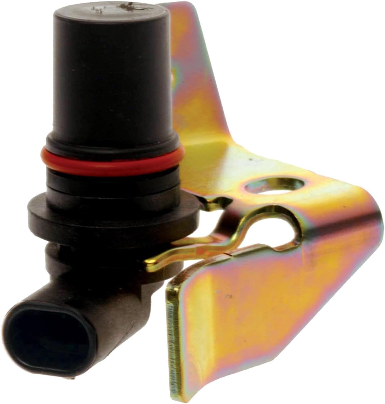
Both are permanent-magnet generators, sometimes called variable reluctance or VR sensors. No power feed, no ground: two wires, a magnet wrapped in a coil, and a toothed rotor passing by. GM's 4L80-E service data describes the output sensor as a device that "contains a permanent magnet surrounded by a coil of wire producing a magnetic field which is interrupted by rotor teeth on the output shaft." The input sensor is described identically, except that its rotor is the machined teeth cut into the outside diameter of the forward clutch housing.
Location matters. The input sensor (TISS, or ISS on scan data) bolts to the case over the forward clutch housing; the output sensor (TOSS, or VSS on early GM trucks) bolts to the case over the output shaft. Both are external - a real difference from the 4L60-E family, where the input sensor lives inside the case on the back of the pump with its wiring routed past a spinning drum. On a 4L80E you are not tearing anything down to reach either one.
The forward clutch housing turns at converter turbine speed in every gear except fourth, so input speed and turbine speed are the same number here. That is why one scan tool labels the PID TURBINE SPEED and another calls it TRANS INPUT SPEED.
What the controller does with the two numbers
Three jobs, and every symptom traces back to one of them:
- Gear ratio. Input speed divided by output speed. Per the Chevrolet Performance Supermatic specification sheet this family runs 2.482, 1.482, 1.000 and 0.750, with 2.077 reverse. So 1,500 RPM input against 1,012 RPM output is 1.48, and you are in second no matter what the shifter says.
- TCC slip speed. Engine speed minus input speed; zero means locked. That derived value is how the module decides whether the converter clutch and the clutch packs are holding.
- Road speed. Output speed becomes vehicle speed, the speedometer, the shift schedule and part of the pressure calculation.
Output speed sensor symptoms
Second gear only, and everything slams
This is the headline symptom, and it is a designed response rather than damage. Losing output speed makes the controller command second gear and take line pressure to maximum so the clutches survive whatever the driver does next. ATRA Technical Bulletin #266 lists exactly those defaults for the output-speed code, and the GM 4L80-E troubleshooting data phrases the loss-of-signal version as "a soft delayed landing to second gear" plus maximum line pressure. Fourth gear and converter apply are both road-speed gated, so they go with it: the truck sits in second, unlocked, and the temperature climbs.
The speedometer drops out with it
On 1994-95 trucks the output signal runs through a VSS signal buffer module that converts 40 pulses per revolution into 4,000 pulses per mile for the speedometer and the PCM. Anything that breaks that chain takes the speedometer with it - a useful confirming symptom, since a transmission-only complaint with a working speedometer usually is not the output sensor.
The two output codes are not the same fault
They point different directions. The circuit-low code sets when no vehicle speed is detected at start off - a dead circuit. The signal-loss code sets when speed has been detected and is then lost - an intermittent. On OBD-II applications these are the SAE generic output speed sensor codes P0722 (no signal) and P0723 (intermittent).
Input speed sensor symptoms
No converter clutch, and no other explanation
The default for a total input speed failure is narrow: the controller inhibits TCC and otherwise leaves the transmission alone. Set conditions are specific - not in park or neutral, engine above 300 RPM, output speed above 200 RPM, input speed below 50 RPM, held two seconds. A truck that shifts all four gears but will not lock the converter, with an input-speed code stored, is behaving as designed.
On OBD-II applications it shows as P0716, input speed sensor performance, or P0717, low input speed sensor circuit voltage.
False slip and ratio codes from a sensor that is only half dead
This is the one that costs people a rebuild. The input-speed code only sets when input speed reads essentially zero. A sensor that still makes a signal but reads low - chipped rotor tooth, weak magnet, marginal connector, a dropout lasting a few hundred milliseconds - never trips it. It corrupts the derived numbers instead.
Low input speed against a correct output speed computes as a low gear ratio; against engine speed it computes as converter slip. The component-slipping code sets when TCC slip exceeds 200 RPM with the converter commanded locked in fourth for two seconds, and the diagnostic notes for it say plainly that an intermittent incorrect speed signal lasting more than two seconds will set it. Both that code and the TCC-stuck code are inhibited once the input-speed code is set, so the ones you actually see are the cases where the sensor was not bad enough to flag itself.
If a 4L80E is setting slip or ratio codes and the pan is not full of friction material, the clutches are not talking to you. The sensors are.
Set conditions and defaults, side by side
| Fault | Sets when | Controller default |
|---|---|---|
| Output speed, circuit low (P0722 family) | Not in P/N, signal voltage constant, engine above 3,000 RPM, output speed below 200 RPM, throttle 10-100 percent, held 3 seconds | Second gear only, maximum line pressure |
| Output speed, signal loss (P0723 family) | Output speed change over 1,000 RPM in a drive range (2,050 RPM in P/N), engine above 300 RPM, held 2 seconds, no range-switch fault stored | Soft delayed landing to second gear, maximum line pressure |
| Input speed (P0716 / P0717) | Not in P/N, engine above 300 RPM, output speed above 200 RPM, input speed below 50 RPM, held 2 seconds | No TCC operation |
| Component slipping | TCC slip above 200 RPM with fourth indicated and TCC locked, not in P/N, held 2 seconds | No TCC, no manual mode |
Testing, in the order that actually narrows it
1. Watch the three speeds together
Put engine speed, trans input speed and trans output speed on one screen and drive it. Input should track engine speed closely with the converter locked; output should rise smoothly with road speed. A value that snaps to zero and back, or sits frozen while the other two move, has named the circuit. The turbine speed PID reads 0 to 8,191 RPM on a Tech 2, so a pegged reading is obvious.
2. Measure resistance at the sensor
GM's 4L80-E diagnostic chart gives 1,000 to 2,000 ohms across the two sensor pins, so open or shorted is an easy call. ATRA's survey of VR sensors across manufacturers puts the family range at roughly 500 to 2,400 ohms, which puts this one squarely in normal territory.
3. Check AC output with the wheels turning
A PM generator makes its own signal, so measure it directly. Drive wheels raised and rotating, a DVOM on AC volts backprobed across the sensor's two circuits at the controller should climb with speed - the GM chart for this unit calls for more than 7 volts AC above roughly 10 mph. If it is low there, repeat at the sensor terminals. Good at the sensor and bad at the controller means wiring; bad at both means the sensor or the rotor.
4. Scope it if it is intermittent
This is the step most people skip and the one that catches the expensive failures. ATRA's GEARS technical staff is direct about it: scan tool graph values are averaged, "so it's easy to miss glitches or low signal output. The best way to check these sensors is a graphing voltmeter or scope," monitored at the control module so you see what the module sees. A damaged rotor tooth shows as one bad cycle per revolution. Amplitude that sags at low speed is normal VR behavior - flux lines do not cut the windings fast enough at low RPM to make much voltage.
5. Inspect the connector and the pigtail before you condemn the sensor
Both sensors sit low on the case in road spray, and green terminals or a cracked pigtail are more common than a failed magnet. Transmission Digest's coverage of the same family of input-speed codes adds one worth knowing: the controller can lose the internally supplied sensor ground, repaired by splicing an external ground into that circuit rather than replacing anything inside the transmission.
Two 4L80E-specific traps
The 1994 four-wheel-drive change. Starting with 1994 production, GM dropped the transmission output speed sensor and its toothed wheel from all 4WD 4L80E units, moving output speed pickup to the transfer case and adding a dedicated 4WD-Low switch input to the PCM. Per ATRA Technical Bulletin #266, output planetary carrier assemblies must not be interchanged between output-VSS and non-output-VSS units. Put a carrier without the toothed wheel into a 1991-93 truck that needs one and you get late or no upshifts, and the failure is subtle: the controller can pick up a 21-pulse-per-revolution signal off the machined slots in the output planetary instead of the 40 pulses per revolution it expects. The unit runs. It just shifts wrong, forever, and no sensor test will find it.
Rebuilt-unit mismatches. The same bulletin says to verify a replacement transmission is equipped with or without the toothed wheel to match the application. Check that first when a freshly installed 4L80E has speed-sensor behavior no amount of new parts will cure.
The repair
Order of operations that does not waste parts:
- Pull codes and freeze frame, and note whether it is a never-saw-speed or a lost-the-speed code.
- Compare engine, input and output speed on one screen during a drive.
- Unplug both sensor connectors and look for oil, corrosion and spread terminals.
- Resistance check both sensors at 1,000 to 2,000 ohms, then AC voltage at the controller and again at the sensor with the wheels turning.
- Scope the circuit if the complaint is intermittent.
- Replace the sensor with its seal. GM part 24203876 serves both positions on this unit, so there is no guessing, and when one fails from age and heat the other has the same miles on it.
- If codes return with good sensors and wiring, verify the output carrier and toothed wheel match the application before going deeper.
If the pan comes off, current service fill for this family is DEXRON-VI, and the Chevrolet Performance sheet for the same case lists roughly 7.7 quarts (7.3 L) for a pan drop and 13.2 quarts (12.5 L) dry.
FAQ
What are the symptoms of a bad speed sensor on a 4L80E?
Losing output speed puts the transmission in second gear only with line pressure at maximum, so it bangs into gear, will not upshift and usually drops the speedometer. Losing input speed is quieter: it still shifts through all four gears, but the converter clutch will not apply. A weak sensor rather than a dead one sets slipping and ratio codes instead, because the controller is doing gear-ratio and slip math on a wrong number.
Where are the speed sensors on a 4L80E?
Both bolt to the outside of the case. The input sensor sits over the forward clutch housing near the front and reads machined teeth on its outside diameter; the output sensor sits over the output shaft at the rear and reads a toothed rotor. Neither needs the pan or valve body removed. On 1994-up four-wheel-drive trucks the transmission output sensor was deleted and output speed comes from the transfer case.
What resistance should a 4L80E speed sensor read?
GM's diagnostic chart for this unit calls for 1,000 to 2,000 ohms across the sensor's two terminals, and open or near-zero condemns it. Resistance alone will not catch an intermittent, though: a sensor can measure correctly and still drop out under vibration, which is why the AC voltage and scope checks matter on a complaint that comes and goes.
Are the input and output speed sensors the same part on a 4L80E?
Yes. Both positions take the same sensor, GM part number 24203876, which also covers the 4L60E, 4L65E and 4L70E. That makes the two-pack the practical buy, since both sensors have the same age, heat cycles and road spray on them.
Can a bad speed sensor cause a 4L80E to stay in second gear?
Yes, and it is the most common cause of that complaint. Second gear with maximum line pressure is the programmed default when the controller loses output speed. The clutches are not slipping; the module removed the shift schedule on purpose to protect them. Fix the signal and the shifts come back with no other repair.
Related guides
- 4L80E P0716: Input Speed Sensor Performance Causes and Fix
- 4L80E Limp Mode: Causes and How to Diagnose It
- 4L80E P1870: Component Slipping / TCC Slip
- 4L80E Won't Shift Into Overdrive
- 4L80E Shift Solenoid Symptoms and Replacement
Need parts for this job?
Speed sensors, internal wiring harnesses, solenoid kits, valve bodies and rebuild kits for the 4L80E and 4L85E, on our own checkout and shipped from the USA.
Shop 4L80E parts →Sources
- AM General Corporation / GM, "Troubleshooting the 4L80E Automatic Transmission" (Supplement 7). Backs the physical description of both sensors as permanent magnets surrounded by a coil interrupted by rotor teeth, the input sensor reading machined teeth on the outside diameter of the forward clutch housing, the mounting locations, the set conditions and defaults for the output-speed circuit-low, output-speed signal-loss, input-speed and component-slipping codes, the 1,000 to 2,000 ohm sensor resistance spec, the more-than-7-volts-AC-above-10-mph output check, and the 0 to 8,191 RPM turbine speed PID range. Note that circuit numbers and controller pin designations in this document are specific to the standalone TCM used in that application. https://gear-report.com/wp-content/uploads/2017/03/Supplement_7_4L80E-Transmission_Troubleshooting.pdf
- ATRA Technical Bulletin #266, "4L80E Updates" (Automatic Transmission Rebuilders Association). Backs the 1994 vehicle speed sensor circuit changes, the deletion of the transmission output speed sensor and toothed wheel on 4WD units, the warning not to interchange output planetary carrier assemblies between output-VSS and non-output-VSS units, the 21-pulse-per-revolution versus 40-pulse-per-revolution problem and the late or no upshifts it causes, the VSS signal buffer module converting 40 pulses per revolution into 4,000 pulses per mile, and the second-gear-only plus maximum-line-pressure default for the output speed code. https://atracom.blob.core.windows.net/bulletins/1995/allyear/atb266.pdf
- GEARS Magazine (ATRA), "Advanced Speed Sensors, Part 1." Backs the variable reluctance sensor operating principle, the roughly 500 to 2,400 ohm resistance range across manufacturers for this sensor style, the loss of signal amplitude at low RPM because flux lines do not expand and contract fast enough across the windings, and the use of a scope pattern to find a damaged tone wheel tooth or excessive signal voltage fluctuation. https://gearsmagazine.com/magazine/advanced-speed-sensors-part-1/
- GEARS Magazine (ATRA), "Sensing Problems: A Look at Common Sensor Failures." Backs the quoted guidance that scan tool graph values are averaged so glitches and low signal output are easy to miss, that a graphing voltmeter or scope monitored at the control module is the correct tool, and that speed sensor failures typically produce no shifts or failsafe operation with codes not always present. https://gearsmagazine.com/magazine/sensing-problems-a-look-at-common-sensor-failures/
- Transmission Digest, "GM 4L70-E ISS DTC P0716 or P0717." Backs the P0716 and P0717 definitions used here (input speed sensor performance and low input speed sensor circuit voltage), the internal-harness routing failure that affects the 4L60-E family's pump-mounted input sensor, and the loss of the controller-supplied sensor ground that is repaired by splicing in an external ground rather than replacing transmission parts. https://www.transmissiondigest.com/gm-4l70-e-iss-dtc-p0716-or-p0717/
- Chevrolet Performance (General Motors), Supermatic 4L85-E Transmission Specifications, part no. 19300175. Backs the gear ratios used for the ratio math (2.482 first, 1.482 second, 1.000 third, 0.750 fourth, 2.077 reverse), the DEXRON-VI fluid specification, and the approximate 7.3 L / 7.7 quart bottom-pan-removal and 12.5 L / 13.2 quart dry fill capacities for this case family. https://www.chevrolet.com/content/dam/chevrolet/na/us/english/index/performance/powertrain/performance-parts/installation-guides/01-images/supermatic-transmission-4l85e-19300175.pdf