A 4L80E in limp mode is one of the more honest failures in this business, because the transmission tells you exactly what state it is in once you know how to read it. Failsafe on this unit is not a vague "reduced power" mode. It is a specific, predictable combination: both shift solenoids de-energized, and the pressure control solenoid de-energized. Everything the customer describes follows from those two facts.
Work it that way and most of these jobs are short. Work it as "the transmission is acting up" and you end up buying a solenoid kit for a truck with a bad ground, or a valve body for a truck with a worn bore in the one valve that feeds every solenoid in the unit.


What limp mode actually is on a 4L80E
The 4L80E gets four forward ratios out of two on/off shift solenoids. The AM General and U.S. Army Ordnance School troubleshooting guide for the HMMWV 4L80E publishes the clutch application chart, and the solenoid column is the part worth memorizing:
| Gear (D range) | 1-2 shift solenoid (A) | 2-3 shift solenoid (B) |
|---|---|---|
| 1st | ON | OFF |
| 2nd | OFF | OFF |
| 3rd | OFF | ON |
| 4th | ON | ON |
Read the second row again. Second gear is the state where both solenoids are off. That is not a coincidence, it is the design. When the module cuts power to the solenoids, or the solenoids lose their feed, the valve body falls into second gear because that is where it sits with no electrical input at all. The truck pulls away in second, will not upshift, and Reverse still works normally because Reverse is selected by the manual valve rather than by a solenoid.
The second half of the signature is the harshness, and that comes from the pressure control solenoid. On the 4L80E the EPC relationship is inverted: current up, pressure down. The same guide publishes the bench spec for the override test:
| Current to pressure control solenoid | Line pressure, psi (kPa) |
|---|---|
| 0.0 - 0.02 A | 157 - 177 (1083 - 1220) |
| 0.30 A | 137 - 162 (945 - 1117) |
| 0.60 A | 88 - 113 (607 - 779) |
| 0.98 - 1.1 A | 35 - 55 (241 - 379) |
Zero current is maximum pressure. So a 4L80E in failsafe applies every element at full line pressure while stuck in a single gear. That is the bang into gear the customer is complaining about, and it is normal for that state. Chasing the harsh shift as its own problem is a detour.
Put the two halves together and you have the textbook complaint: starts in second, no upshifts, slams into gear, Reverse is fine. If that is what you have, you are looking for something that killed the solenoid circuits, not something that killed a clutch.
Read the stuck-shift pattern, not just the code number
GM's published diagnostic parameters for the 4L80E do something genuinely useful here: for each shift solenoid performance DTC, the table lists the resulting shift pattern the truck will exhibit. That turns a road test into a diagnosis before you ever pull a code.
| DTC | What GM's monitor sees | Stuck shift pattern |
|---|---|---|
| P0751 Shift Solenoid A Performance | Commanded 1st but ratio is 2nd for over 2.0 sec, and commanded 4th with TCC locked but ratio is 3rd for over 3.75 sec | 2-2-3-3 |
| P0752 Shift Solenoid A Performance | Commanded 2nd but ratio is 1st for over 2.25 sec | 1-1-4-4 |
| P0756 Shift Solenoid B Performance | Commanded 1st but ratio is 4th for over 2.5 sec, and commanded 2nd but ratio is 3rd for over 2.7 sec | 4-3-3-4 |
| P0757 Shift Solenoid B Performance | Commanded 3rd but ratio is 2nd for 2.25 sec or more | 1-2-2-1 |
The module decides all of this by math, using gear ratio windows you can verify yourself on a scan tool. GM's acceptance ranges are 1st 2.52 to 2.42, 2nd 1.52 to 1.44, 3rd 1.02 to 0.98, and 4th 0.77 to 0.727. Divide input speed by output speed in a steady gear and compare. If your calculated ratio lands in a window that does not match the commanded gear, the hydraulics are not doing what the module asked, and you have confirmed the fault without opening anything.
Two enable conditions in those same tables save a lot of wasted work. The performance DTCs require system voltage above 10.0 volts, while the plain electrical DTCs (P0753, P0758, P2761) only require above 8.0 volts. Both also require transmission fluid temperature between roughly 20 and 130 degrees C. A truck with a marginal battery or a cold transmission can sit in default all day and store nothing that points at the real fault. Check charging and grounds first, and get the unit up to temperature before you judge the code set.
Cause 1: the solenoid circuits and the internal harness
This is the most common cause and the easiest to confirm, because you are checking against published resistance values instead of guessing. From the Army and AM General component resistance chart, measured at the transmission pass-through connector:
- 1-2 shift solenoid: 18 to 24 ohms
- 2-3 shift solenoid: 18 to 24 ohms
- Pressure control (EPC) solenoid: 3.5 to 5.2 ohms
- TCC solenoid: 10 to 14 ohms
The detail that explains whole-unit failures sits in the wiring column: the red feed wire for the 1-2 solenoid, the 2-3 solenoid and the TCC solenoid is spliced internally to a single pin, pin E. One feed serves all three. When that splice or the internal harness fails, you do not lose one solenoid, you lose the solenoid side of the transmission at once, and the unit drops straight into the both-off state: second gear, maximum pressure. If you measure two or three solenoids open at the connector but they read correct at the component itself, stop ordering solenoids and replace the internal harness.
The electrical DTCs themselves are simple circuit monitors. GM sets P0753 (shift solenoid A electrical), P0758 (shift solenoid B electrical) and P2761 (TCC PWM electrical) on an invalid output state for 43 counts out of 50, checked continuously with the engine running above 400 RPM for more than 7 seconds. That is a fast, unambiguous test. An electrical DTC on this unit is a real circuit fault, not a performance inference.
Cause 2: the EPC circuit and line pressure
If the shift solenoid circuits check out, gauge the unit. The line pressure test spec for the 4L80E, from the same guide, is worth taping inside the toolbox lid:
- Park, Neutral and both Drive ranges: minimum 35 psi (241 kPa) at idle, rising to a maximum of 171 psi (1179 kPa) at larger throttle openings.
- Reverse: minimum 67 psi (462 kPa) at idle, rising to a maximum of 324 psi (2234 kPa).
- Use a gauge rated 325 to 350 psi. A 200 psi gauge will not survive a Reverse test on this transmission.
Then run the pressure control solenoid override on the scan tool, stepping current up in increments and letting the gauge settle 3 to 5 seconds between steps. Pressure must fall as current rises, tracking the table above. The guide gives the two interpretations plainly: consistently high pressure points at the TCM, the wiring or the solenoid, while consistently low pressure points at the pump or a hydraulic circuit fault. If pressures are low in every range, suspect pump damage, a blown-out cup plug, cross leakage or a worn bushing. If pressure is high, look at the pressure control solenoid, the reverse/boost or pressure regulator valves, a bad TCM ground, or a poor solenoid connection.
Cause 3: the valve that mimics an electrical fault
This is the one that gets missed, and it is the reason a fresh set of solenoids sometimes does not fix a 4L80E limp complaint. Line pressure in the 4L60E and 4L80E family is regulated at roughly 115 psi and fed to the shift solenoids, the pressure control solenoid, the TCC solenoid and the shift valves. Between line pressure and those solenoids sits the actuator feed limit (AFL) valve.
Per Sonnax, the AFL valve in the 4L80E and 4L85E has a large reaction area on the spring end, which side-loads the valve and makes the bore unusually prone to wear. The EPC solenoid continuously oscillates the torque signal and AFL oil, which increases valve movement and accelerates that wear. As the bore opens up, oil pressure to the shift solenoids drops, and the same AFL oil loss pulls line pressure down with it.
The symptom list Sonnax attributes to AFL bore wear reads like a limp mode complaint sheet: wrong gear starts, 2nd gear starts, no 4th, 2-3 neutral, solenoid performance codes, low solenoid feed pressure, band failure and clutch failure. Every one of those is something you would otherwise blame on a solenoid or a module.
The tell is the mismatch. Solenoid resistance in spec, commands correct on the scan tool, no electrical DTCs, but performance and ratio codes that keep coming back and a unit that will not hold a commanded gear. A good solenoid with no oil behind it behaves exactly like a bad solenoid. The repair is the bore, not the electronics: Sonnax sells an oversized hard-anodized AFL valve with a wear-resistant sleeve (kit 34200-16K) for this failure, and the Sonnax valve body layout for the 4L80E and 4L85E lists the AFL valve against incorrect gear engagement at startup, clutch deterioration, solenoid performance codes, band failure and low solenoid feed pressure.
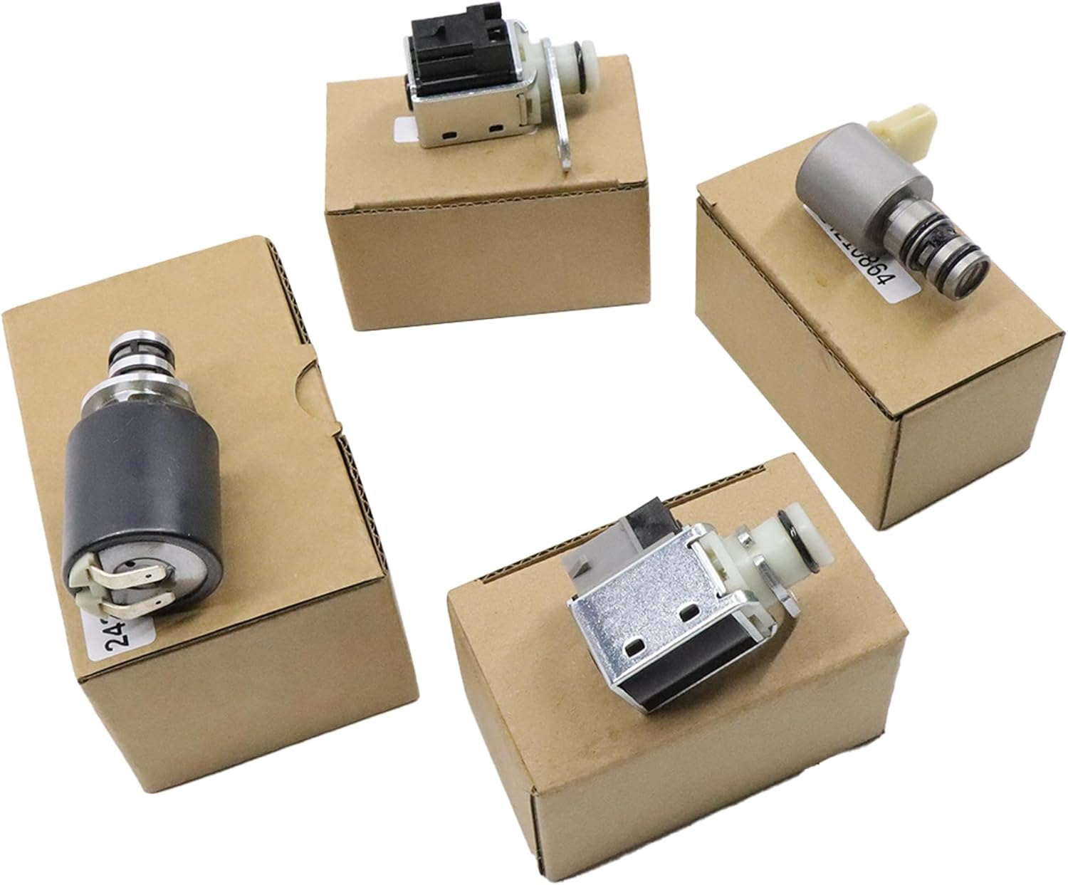
4L80E shift and EPC solenoids, internal wire harnesses, pressure switch assemblies, valve bodies, filters and rebuild kits — shipped from the USA.
Shop 4L80E parts →Cause 4: the pressure switch assembly and P1810
The transmission range pressure switch assembly is a set of five normally-open pressure switches feeding three signal circuits, referred to as range signals A, B and C. The module reads the combination of those three to decide which range the driver selected. Two of the possible combinations are flagged in the valid combination chart as illegal: A-ON/B-OFF/C-ON, and A-ON/B-ON/C-ON. When the module sees an impossible combination, it can no longer trust the range input, and default behavior follows.
GM's P1810 monitor has more than one way to fail, and two of them are worth knowing:
- The startup test runs once per power-on cycle. GM's Fail Case 2 checks whether the pressure switch assembly indicates D2, D4 or Reverse before and after engine start, with input speed above 200 RPM. The table states explicitly that this test runs only once per power-on cycle — pass, fail or invalid, it will not run again until the PCM powers down. If you are trying to reproduce it, a key cycle is not optional, it is the whole test.
- The range-versus-ratio test. Fail Case 3 compares the selected range against the calculated ratio: the switch says Park or Neutral while ratio is at or below 1.05, or it says Reverse while the ratio sits inside the drive range, or it says a drive range while the ratio indicates Reverse. GM's reference windows are drive ratios 2.63 to 0.95 and Reverse 2.05 to 2.11. Fail times are 15 seconds for the first two cases and 7 seconds for the third.
The practical point: a failed pressure switch assembly is a cheap part that produces expensive-looking symptoms, and it is accessible with the pan down. Check it before the unit comes out.
Cause 5: the fault that is not in the transmission
On 1994 and newer 6.5-liter diesel trucks with the electronic injection pump, a worn pump can produce transmission symptoms that no amount of transmission diagnosis will explain. The Sonnax TASC Force documented the mechanism in Transmission Digest: the accelerator pedal position sensor is the main input for both fueling and commanded line pressure. When an internal leak lets the pump deliver more fuel than the computer asked for, the truck accelerates from a stop on 2 to 10 percent throttle instead of the normal 50 to 100 percent. The module obediently commands low line pressure for what it reads as a light load, and you get soft sliding shifts, slippage, and burned forward, intermediate and direct clutches.
The test takes two minutes and no tools. Engine hot, transmission in Park or Neutral, slowly raise engine speed and try to hold it at 2,000 RPM. If the speed keeps climbing while you hold the throttle steady, suspect the pump. Confirm it with a scan tool: normal fuel rate is 10 to 13 mm at idle, and a reading below 6 mm at idle indicates the engine is getting extra fuel while the computer cuts back to hold speed. GM extended warranty coverage on these pumps from five years/100,000 miles to 11 years/120,000 miles under special policy bulletin #00064A.
The unplug test, and the trap inside it
Disconnecting the case connector is the fastest way to split electrical from hydraulic on a 4L80E. With the connector off, the module is out of the loop and the transmission runs its failsafe pattern. If the complaint changes, the fault is electrical. If it does not, move on to hydraulic and mechanical.
There is a catch that the TASC Force spells out, and it has cost people a diagnosis. With the case connector unplugged, line pressure goes to an uncontrolled maximum value. That much pressure can overcome a subtle internal leak that is perfectly capable of causing the original complaint at normal pressure. The unit passes the test and the leak goes back out the door with the truck. Treat a pass on the unplug test as evidence about the electrical side, not as proof that the hydraulics are healthy.
The broader method is the one worth keeping: split the circuits. Test the hydraulics with a gauge in the specific gear that uses the failing element, test the electrical side by removing the computer from the equation, then test mechanically. Keep a line pressure spec sheet and a clutch and band application chart on the bench so you can tell which elements a given gear actually uses before you start guessing.
Order of operations that works
- Battery, charging and grounds. Confirm you are above 10.0 volts running, or the performance monitors will not even run.
- Record freeze frame before clearing anything. The stored code tells you which monitor tripped first; clearing it throws away the only ordered evidence you have.
- Road test against the stuck-shift table. 2-2-3-3, 1-1-4-4, 4-3-3-4 and 1-2-2-1 each name a specific solenoid fault before you plug anything in.
- Measure solenoid resistance at the pass-through connector. 18 to 24 ohms on both shift solenoids, 3.5 to 5.2 on the EPC, 10 to 14 on the TCC. Two or three out of spec at the connector but correct at the component means internal harness.
- Gauge line pressure in every range, then run the EPC override and confirm pressure falls as current rises.
- Drop the pan. Inspect the pressure switch assembly and read the debris. Clutch material means the electrical fault is a symptom of something already worn.
- Suspect the AFL bore when everything electrical checks out and the performance codes keep returning.
Keeping a 4L80E out of limp mode
Most 4L80E failsafe events trace back to heat, fluid and connections rather than to a part that simply wore out. The Army guide specifies DEXRON-III for these units and sets normal operating temperature at 180 to 200 degrees F (82 to 93 degrees C), reached after roughly 15 miles of driving; verify the fill spec for your specific year and application before you service one. Capacities for that application are approximately 5 quarts refill after a filter change, 11.5 quarts dry fill after overhaul, and 1 to 2 quarts in the cooler and lines.
Do not overfill. Excess fluid gets churned into foam, and aerated fluid causes overheating, shift problems and clutch wear, which is how a fluid service turns into a solenoid performance code three months later. Beyond that: keep the cooler flowing, inspect the case connector and internal harness any time the pan is off, and when a unit comes apart for any reason, address the actuator feed limit bore rather than reusing a worn one and hoping.
Related reading: how to check line pressure, bench testing transmission solenoids, and reading transmission live data.
FAQ
What gear does a 4L80E go into in limp mode?
Second gear. Both shift solenoids are de-energized in failsafe, and the 4L80E clutch application chart shows second gear is the state where the 1-2 solenoid and the 2-3 solenoid are both off. The truck pulls away in second and will not upshift. Reverse is selected by the manual valve rather than by a solenoid, so Reverse usually still works normally.
Why does a 4L80E shift so hard in limp mode?
Because the pressure control solenoid is de-energized and line pressure goes to maximum. On the 4L80E the EPC relationship is inverted: more current means less pressure. At 0.0 to 0.02 amps the line pressure spec is 157 to 177 psi, while at 0.98 to 1.1 amps it drops to 35 to 55 psi. With no current the transmission applies everything at full pressure, which is what produces the bang into gear.
Can a weak battery put a 4L80E in limp mode?
It can cause the symptom and hide the evidence. GM's monitor tables require system voltage above 8.0 volts for the electrical DTCs and above 10.0 volts for the shift solenoid performance DTCs. Below those floors the module will not run the tests, so you can get default behavior with no useful code stored. Verify charging and grounds before condemning anything inside the transmission.
Will replacing the shift solenoids fix a 4L80E limp mode?
Only if the solenoids or their circuits are actually the fault. Check resistance first: the 1-2 and 2-3 shift solenoids should read 18 to 24 ohms, the pressure control solenoid 3.5 to 5.2 ohms, and the TCC solenoid 10 to 14 ohms. If resistance is in spec, look at the internal harness and at actuator feed limit valve bore wear, which starves good solenoids of oil and sets the same performance and ratio codes.
Is it safe to drive a 4L80E in limp mode?
Only far enough to get it off the road. The unit is running at maximum line pressure in a single gear with no torque converter clutch management, and the underlying fault is often slipping clutches that are still making debris. Continuing to drive it turns an electrical or valve repair into a rebuild.
Sources
- General Motors — "2005 4L80E Transmission Diagnostic Parameters" (GM Service Information, Mode $06 monitor tables). Backs every DTC threshold in this article: the P0751, P0752, P0756 and P0757 stuck shift patterns (2-2-3-3, 1-1-4-4, 4-3-3-4, 1-2-2-1) and their commanded-gear/ratio fail times; the gear ratio acceptance windows of 2.52-2.42, 1.52-1.44, 1.02-0.98 and 0.77-0.727; the 10.0 volt enable floor on performance DTCs versus 8.0 volts on electrical DTCs; the 20 to 130 degree C fluid temperature enable window; the 43-of-50 count criterion for P0753, P0758 and P2761; and the P1810 Fail Case 2 once-per-power-on startup test plus the Fail Case 3 range-versus-ratio windows (drive 2.63 to 0.95, Reverse 2.05 to 2.11). gsi.ext.gm.com
- U.S. Army Ordnance Mechanical Maintenance School / AM General — "4L80E Transmission Troubleshooting Guide," Warrant Officer Training Material, Supplement 7, January 2008. Backs the clutch application chart solenoid states (1st A-ON/B-OFF, 2nd A-OFF/B-OFF, 3rd A-OFF/B-ON, 4th A-ON/B-ON); the component resistance chart (shift solenoids 18-24 ohms, pressure control solenoid 3.5-5.2 ohms, TCC solenoid 10-14 ohms) and the internal splice of the red feed to pin E; the line pressure test specs (35 psi minimum at idle to 171 psi maximum in P/N/D, 67 psi to 324 psi in Reverse, 325-350 psi gauge capacity); the pressure control solenoid current-versus-pressure table and its high/low interpretations; the five normally-open pressure switches on three range signals and the illegal switch combinations; and the DEXRON-III specification, 180-200 degrees F operating temperature, 5 quart refill, 11.5 quart dry fill and 1-2 quart cooler capacity. gear-report.com
- Transmission Digest / Sonnax TASC Force — "Diagnosing the Elusive No Reverse with the 4L80-E," Randall Schroeder, January 2012. Backs the split-the-circuits method (hydraulic, electrical, mechanical), the requirement to pressure test in the specific gear that uses the suspect element, and the case-connector unplug test — including the warning that with the connector off, line pressure goes to an uncontrolled maximum value that can mask an internal leak. transmissiondigest.com
- Transmission Digest / Sonnax TASC Force — "Low Line Pressure in 4L80-E in Diesel-Powered Trucks," Gregg Nader, March 2002. Backs the electronic injection pump mechanism (the APP sensor as the shared input for fueling and commanded line pressure), the 2-10 percent throttle acceleration signature, the 2,000 RPM steady-throttle test, the 10-13 mm normal idle fuel rate and the below-6 mm indicator, and GM special policy warranty bulletin #00064A extending coverage to 11 years/120,000 miles. transmissiondigest.com
- Sonnax — Actuator Feed Limit Valve Kit 34200-16K, product and application data (GM 4L80-E, 4L85-E). Backs the AFL bore wear mechanism (large reaction area, side loading, EPC oscillation of the torque signal accelerating wear), the resulting low pressure at the shift and EPC solenoids, and the symptom list: wrong gear starts, 2nd gear starts, no 4th, 2-3 neutral, solenoid performance codes, low solenoid feed pressure, band failure and clutch failure. sonnax.com
- Sonnax — "Hydraulics Fundamentals Part VII: AFL/Solenoid Modulator Valves" and "GM 4L80-E, 4L85-E Valve Body Layout." Backs the approximately 115 psi regulated line pressure feeding the shift solenoids, pressure control solenoid, TCC solenoid and shift valves; the AFL valve's regulation method and its susceptibility to bore wear from side loading; and the valve-by-valve symptom map used in this article (boost valve to uncontrollable line rise, AFL valve to incorrect gear engagement at startup and low solenoid feed pressure, shift valves to 2nd gear starts and missing 4th). sonnax.com
4L80E A & B shift solenoid set → or browse all 4L80E parts →