P0791 on a Super Duty with a TorqShift tends to show up next to a drivability complaint: a truck that stays in one gear, flares or bangs on the 1-2, quits locking the converter, or comes in on a hook in limp mode. The intermediate shaft speed (ISS) sensor is the obvious suspect, but on a 5R110W it shares a housing, a connector, a 12-volt supply and a ground with the turbine shaft speed (TSS) sensor, and it shares that same supply with the output speed sensor and the range sensor. That changes how you diagnose it.
This post covers one code: what the PCM has to see to set P0791 on a 5R110W, how it relates to P0793 and P0794, what the ISS actually reads, which scan-tool numbers tell you the signal is good, and the order I check things. Specs come from the ATSG TorqShift manual, Ford's OBD system summaries, Transmission Digest and Gears (ATRA), all listed under Sources. For the other two speed signals on the same unit, see our 5R110W P0715 guide and 5R110W P0720 guide.
What P0791 means on this unit
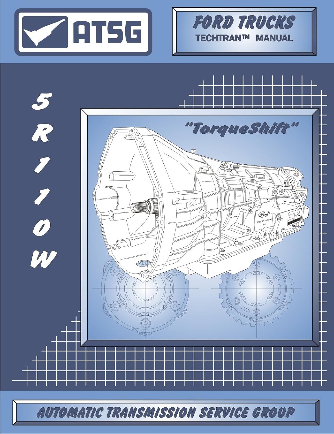
The 5R110W came out for model year 2003 in the Super Duty and Excursion behind the 6.0L diesel, and it later went behind the 6.8L V10 and the 6.4L diesel. The PCM runs it, there is no separate TCM, and it times clutch applies and releases from three hall-effect speed inputs: TSS, ISS and OSS. Road speed comes from the ABS module over the network, not from the transmission.
Ford's 2004 diesel OBD system summary puts it plainly in the 5R110W section: if the engine is above converter stall speed and load is high, the PCM infers the truck must be moving, and "insufficient output from the ISS sensor" sets P0791. The functional check behind that sentence runs continuously and looks like this:
| Item | Ford 2004 5R110W ISS functional check |
|---|---|
| Code | P0791 |
| Gear selector | Any forward range |
| Proof the truck is moving (any one) | Engine above 3000 rpm (above stall) OR turbine shaft 800 rpm OR output shaft 500 rpm OR vehicle speed 10 mph |
| Fail threshold | Positive driving torque and ISS below 250 rpm for 5 seconds |
| Monitor | Continuous, 30 second duration |
Ford's 2010 summary carries the same wording for the 5R110W, so the logic did not change across the 6.0L, 6.4L and V10 years. Read that table carefully, because it tells you what the code can and cannot prove. P0791 does not mean "the ISS is bad." It means the other inputs say the truck is pulling and the ISS reported almost nothing for five seconds. A dead sensor does that. So does an open signal wire, a lost 12-volt supply, a bad ground, or a short that drags the shared reference down.
P0791 vs P0793 vs P0794
The ATSG 5R110W code chart lists three ISS rows: insufficient input from the ISS, no input from the ISS, and ISS signal intermittent. Those line up with P0791, P0793 and P0794 in the chart's code column. P0791 is the rationality code that Ford's monitor documents in detail. If you see P0793 with it, think hard open or no supply. P0794 points at a connection that comes and goes, which is a wiring and connector job far more often than a sensor job.
What the ISS reads and why the truck misbehaves without it
Per ATSG, the TSS and ISS are both hall-effect sensors built into one housing, mounted on the outside of the case, and fed 12 volts and a ground. The TSS reads teeth on the coast clutch input hub. The ISS reads the adjacent overdrive ring gear teeth. Both read 30 teeth per revolution, and ATSG lists their jobs as line pressure, shift timing and converter clutch control.
The overdrive ring gear is the output of the front planetary, which is what feeds the main gear train. That is why the PCM needs it. ATSG notes that 2nd gear on the 5R110W comes from applying the overdrive clutch to the 1st-gear setup, and that cold-mode 4th comes from engaging the overdrive clutch in 3rd. Those shifts happen entirely in the front unit. Without ISS, the PCM can see TSS and OSS but cannot tell which half of the transmission is doing what, so it loses its view of the 1-2 shift, and it has no way to separate a slipping overdrive clutch from a slipping main-box clutch.
Gears' Keith Clark describes the typical result of a speed sensor failure as no shifts or failsafe operation, with or without codes. On a TorqShift that shows up as a truck stuck in a gear, poor power from a high-gear launch, no converter lockup, and a harsh engagement or shift as the PCM falls back to maximum pressure strategy.
The scan-tool math that proves ISS is good
Before unplugging anything, graph TSS, ISS and OSS rpm with engine rpm and vehicle speed on a road test. Transmission Digest's TorqShift overview gives the ratios: 1st 3.09, 2nd 2.20, 3rd 1.54, 4th 1.09 (cold mode only, below 5 degrees F per ATSG), 5th 1.00, 6th 0.71. Because the 1-2 shift and the cold-mode 3-4 shift are made by the overdrive clutch alone, you can split the ratio in two:
- 1st gear: TSS divided by ISS should be about 1.40 (3.09 / 2.20), and ISS divided by OSS about 2.20.
- 2nd gear: TSS and ISS should read the same, since the overdrive clutch locks the front unit, and ISS divided by OSS should still be about 2.20.
- Any gear: ISS should never drop toward zero while TSS and OSS are both up and the truck is under power. That is exactly the condition the Ford monitor flags.
Those numbers come from simple division of the published ratios, not from a Ford spec table, but they are a fast way to tell a dead signal from a slipping clutch. If ISS tracks properly and the TSS:ISS split comes out wrong during or after the 1-2 shift, you have a mechanical problem in the front unit, not a sensor problem. If ISS drops out while the other two keep reading, chase the ISS circuit.
Clark also warns that scan data is averaged, so a dropout of a few milliseconds can fall between frames. A clean graph does not clear an intermittent. If the code keeps coming back, scope it.
Read the code pattern first
- P0791 alone, TSS normal. The ISS has its own signal wire but shares everything else with TSS. A healthy TSS means supply and ground at the housing are probably good, so focus on the ISS signal path: the gray/orange wire, its terminal at the sensor connector and at the PCM, and the sensor itself.
- P0791 with P0715 (TSS). Both halves of the same housing lost signal. Look at the shared reference, the shared ground and the connector before buying a sensor.
- P0791 with OSS or range sensor codes (P0720-P0722, P0706, P0708, P1705), or a no-start. Something is pulling down the shared reference voltage. This is the case worth knowing about, covered next.
- P0791 with solenoid or pressure control codes. Something is hitting a whole connector or the PCM. On a 6.0L, Transmission Digest documented diesel fuel from a leaking water-in-fuel sensor wicking through the C138E connector into the PCM and setting a string of random transmission codes.
- P0791 with shift solenoid functional codes (P2700-P2704, or P0751-P0772 on later years). Ford's monitor uses TSS and ISS to judge those clutch systems, so a bad ISS can set them as a side effect. Fix the sensor circuit first, clear codes, and see what returns.
The shared reference voltage trap
Per ATSG's wiring schematic, PCM connector "B" pin 1 (pink/white) is the reference voltage for the TSS/ISS housing and for the OSS, and pin 22 (black/white) is a ground shared by all of them. The signals come back on separate wires: ISS on pin 27 (gray/orange), OSS on pin 28, TSS on pin 29.
Transmission Digest's May 2011 Tech/Talk adds a piece most techs never see coming. It says pin 1 of connector "B" also feeds the transmission range sensor, and that inside the PCM it is tied to the reference circuit for the electronic fan clutch speed sensor (connector "C" terminal 46). A shorted fan clutch speed sensor can pull that voltage down and set range sensor codes, speed sensor codes across the P0715-P0722 range, and even a no-start. Their test is simple: unplug the fan clutch connector on the driver side of the fan shroud, clear codes and drive it. If the codes stay gone, replace the fan clutch speed sensor.
The other documented case is the one in Wayne Colonna's "An Identity Crisis" in Transmission Digest: a 2010 F-450 with a 6.8L whose speed PIDs all read zero. A new OSS did nothing, and the actual fault was broken wires at the TSS/ISS connector. If that connector is damaged enough to take out the shared circuits, it can certainly take out the ISS signal by itself.
Electrical checks, in order
1. Connector and harness at the case
Unplug the TSS/ISS connector and look for broken or stretched wires right at the connector body, pushed-back terminals, green corrosion and fluid inside. Follow the harness for rub points at the crossmember, the exhaust and the transfer case on 4x4 trucks. On a 6.0L, check C138E for diesel fuel while you are there.
2. Supply and ground at the sensor connector
Key on, sensor unplugged. ATSG's connector view gives terminal 1 reference voltage (pink/white), terminal 2 ground (black/white), terminal 3 TSS signal (green/white) and terminal 4 ISS signal (gray/orange). Expect battery-level voltage on terminal 1. Load the ground rather than reading it open-circuit. Gears' Sean Boyle points out that voltage drop on a hall sensor ground lifts the low side of the signal, so the module may stop seeing clean transitions even though a meter reads "good." If the reference is low, unplug the fan clutch speed sensor and the range sensor one at a time and see if it comes back up.
3. ISS signal wire end to end
Check continuity from sensor connector terminal 4 to PCM connector "B" pin 27, then check that wire for shorts to ground and to voltage. Flex the harness along its length while you watch the meter. A wire that is fine at rest and opens when moved is how P0794 and intermittent P0791 happen.
4. Scope the signal
Clark recommends scoping at the PCM so you see what the module sees. A good hall signal is a square wave with a clean pull to near zero, constant amplitude, and frequency that rises with shaft speed. To chase an intermittent, use Boyle's method: warm the sensor with a heat gun and tap the housing while watching for the pattern to break up. A DVOM averages the switching and will hide that.
5. Resistance, with limits
ATSG lists 325-485 ohms at 70 degrees F across terminals 1 and 4 for the ISS (and 1 and 3 for the TSS). An open reading condemns the sensor. An in-range reading does not clear it, because, as Boyle explains, the electronics inside a hall sensor make resistance a poor pass test.
Shop the part for this fix: 5R110W input/output speed sensor set
OEM-spec TSS/ISS and OSS sensor set (3C3Z-7H103-AA) for the 5R110W, for when supply, ground, the gray/orange signal wire and the connector all check good and the scope shows the ISS itself dropping out.
See the speed sensor set at CoreTransmissionPartsReplacing the TSS/ISS sensor
The TSS and ISS are one part, so a P0791 sensor replacement is a TSS replacement too. Clean the area before pulling it so dirt does not drop into the case.
- Look at the tip. Heavy metallic fuzz on the magnet can distort the signal and tells you something is wearing inside.
- Install a new O-ring lubricated with clean ATF.
- Torque the retaining bolt to 9 N-m (80 in-lb), per the ATSG assembly procedure. It is a small bolt in aluminum.
- Check the fluid level hot. Ford's Motorcraft ATF chart lists MERCON LV for the 5R110 TorqShift, including back-service on early units. The 2009 Super Duty owner guide lists about 17.5 quarts (16.6 L) including the cooler. Set the level by the dipstick, not by pouring a number.
- Clear codes and road test through every gear while graphing TSS, ISS and OSS. Check the 1st and 2nd gear splits from the section above.
When a new sensor does not fix P0791
- The shared reference. If you did not check the fan clutch speed sensor and the range sensor, go back. That is the documented trap on this unit.
- The PCM connector and PCM. Inspect connector "B" for corrosion or fuel. Replace the PCM only after a clean signal at pin 27 still sets the code.
- The target. The ISS reads the overdrive ring gear. A damaged ring gear or excessive end play can give a weak signal no outside part will fix. That is a teardown finding.
- A real slip. If ISS reads fine and the TSS:ISS split is wrong after the 1-2, the overdrive clutch is the problem. See our 5R110W slipping guide and limp mode guide.
Need parts for this job?
If the sensor circuit checks out and the diagnosis points inside the unit, our 5R110 parts page has solenoid kits, valve bodies, pumps and rebuild kits for the TorqShift, all on our own checkout.
FAQ
What does P0791 mean on a 5R110W?
It means the PCM saw the truck pulling under positive torque, confirmed by engine, turbine, output or vehicle speed, while the intermediate shaft speed (ISS) sensor reported less than 250 rpm for 5 seconds. Ford's OBD summary calls this insufficient output from the ISS sensor. It points at the ISS circuit, not automatically at the sensor.
Where is the intermediate shaft speed sensor on a 5R110W?
Per ATSG it shares one housing with the turbine shaft speed sensor, mounted on the outside of the transmission case. The ISS half reads the overdrive ring gear teeth and the TSS half reads the coast clutch input hub. The retaining bolt torques to 9 N-m (80 in-lb).
Can a fan clutch problem cause P0791 on a Super Duty?
It can. Transmission Digest reported that the electronic fan clutch speed sensor reference is tied inside the PCM to the reference that feeds the range sensor and the transmission speed sensors. A shorted fan clutch sensor can pull that voltage down. Unplug the fan clutch connector, clear codes and drive the truck to test it.
Do I have to replace the TSS if only P0791 is set?
On a 5R110W the TSS and ISS are built into one housing, so if the ISS half has failed you replace both. Confirm it first: check supply and ground at terminals 1 and 2, the ISS signal wire to PCM pin 27, and scope the signal before buying the part.
Related guides
- 5R110W P0715: Input Turbine Speed Sensor Causes & Fix
- 5R110W P0720: Output Speed Sensor Causes & Fix
- 5R110W P0500: Vehicle Speed Sensor Causes & Fix
- 5R110W Input/Output Speed Sensor Symptoms
- 5R110W Limp Mode Causes
Sources
- ATSG, Ford 5R110W (TorqShift) technical manual (2004). Backs the ISS code chart rows (insufficient, no input, intermittent), the TSS/ISS shared housing, the coast clutch hub and overdrive ring gear targets at 30 teeth per revolution, the sensor jobs, the connector terminals and colors, PCM connector "B" pins 1, 22, 27, 28 and 29, 325-485 ohms, the overdrive clutch role in 2nd and cold-mode 4th, and the 9 N-m (80 in-lb) bolt torque. ATSG manual (PDF)
- Ford Motor Company, 2004 MY OBD System Operation Summary for Diesel Engines (DOBDSM404, archived copy), 5R110W section. Backs the P0791 definition, VSS from the ABS system, and the ISS functional check entry conditions and the less-than-250-rpm-for-5-seconds threshold. Ford OBD summary (PDF, archive.org)
- Ford Motor Company, 2010 MY OBD System Operation Summary (OBDSM1001, archived copy), 5R110W section. Backs the unchanged P0791 logic in later years. Ford OBD summary (PDF, archive.org)
- Transmission Digest, "May 2011 Issue" Tech/Talk, "5R110W: Transmission-range-sensor/speed-sensor faults or no start." Backs the shared PCM reference to the range sensor and TSS/ISS/OSS, the fan clutch speed sensor link (connector "C" terminal 46), and the unplug-and-drive test. transmissiondigest.com
- Transmission Digest, Wayne Colonna, "An Identity Crisis." Backs the 2010 F-450 6.8L case with all speed PIDs at zero and broken TSS/ISS connector wires as the fault. transmissiondigest.com
- Transmission Digest, Dale England, "Ford 5R110W ('TorqShift')." Backs the 2003 introduction and the 3.09/2.20/1.54/1.09/1.00/0.71 ratios. transmissiondigest.com
- Gears Magazine (ATRA), Sean Boyle, "Advanced Speed Sensors Part 1." Backs hall sensor supply and ground checks, ground voltage drop, DVOM limits, the heat-and-tap test, and why resistance does not prove a hall sensor good. gearsmagazine.com
- Gears Magazine (ATRA), Keith Clark, "Sensing Problems: A Look at Common Sensor Failures." Backs failsafe behavior with or without codes, scan data averaging, and scoping at the module. gearsmagazine.com
- Ford Customer Service Division, Motorcraft ATF quick reference chart, and the 2009 F-250/350/450/550 Owner's Guide (archived). Back MERCON LV for the 5R110 and the 17.5 qt (16.6 L) capacity including the cooler. Ford ATF chart (PDF) / Ford owner guide (PDF, archive.org)