P0720 on a Super Duty with a TorqShift usually arrives with a complaint that sounds bigger than a sensor code: the truck will not shift, it feels down on power, the speedometer is doing something strange, or it is sitting in one gear. The output shaft speed (OSS) sensor is cheap and easy to reach, so it gets replaced first. Sometimes that is the right call. On a 5R110W there is a well-documented case where it is not, and it is worth knowing before you order anything.
This post covers one code: what the PCM has to see to set P0720 on a 5R110W, how it differs from P0721 and P0722, why a fault on a completely different sensor can set it, and the order I check things so the truck gets fixed once. Specs come from the ATSG TorqShift manual, Transmission Digest, Gears (ATRA) and Ford, all listed under Sources. For the input side of the same system, see our 5R110W P0715 guide.
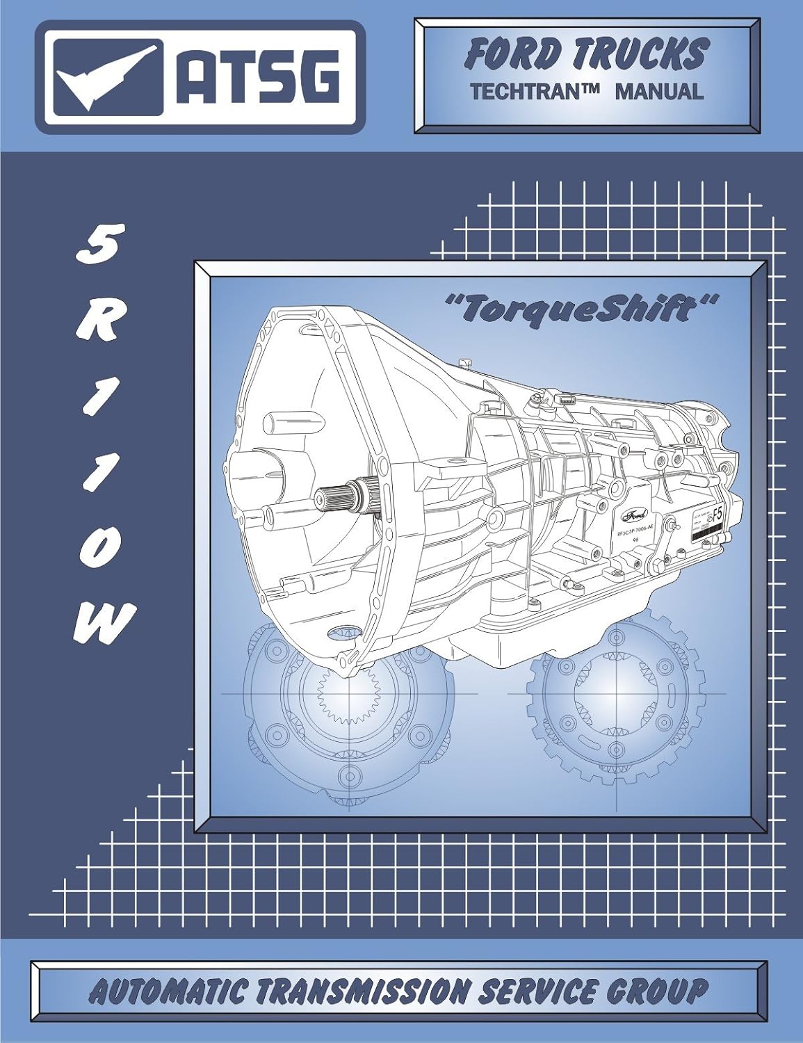
What P0720 means on this unit
The 5R110W came out for model year 2003 in the Super Duty and Excursion behind the 6.0L diesel (Transmission Digest's unit overview), and it was later used behind the 6.8L V10 and the 6.4L diesel. It is a clutch-to-clutch transmission. The PCM times every clutch apply and release from shaft speeds, and it knows a shift is finished when the ratio of turbine speed to output speed matches the target gear. Output speed is half of that math.
The ATSG 5R110W diagnostic chart splits output speed faults into three codes:
| Code | ATSG description | What it points at |
|---|---|---|
| P0720 | PCM detected a loss of OSS signal during normal operation | The signal was there, then it went away. Think intermittent: a connector, a wire that opens under flex or heat, or a shared supply or ground dropping out. |
| P0721 | PCM has detected a noisy OSS signal | Signal present but dirty. Think interference, a poor ground, debris on the sensor tip, or a damaged tone target. |
| P0722 | PCM has detected no OSS signal | No signal at all. Think open circuit, no reference voltage, no ground, or a dead sensor. |
P0720 by itself says the circuit worked at some point and then quit. P0720 and P0722 stored together, which is common, says the signal dropped out and then never came back on that drive. Either way, start by asking what changed while the truck was moving.
What the OSS does and why the truck acts up without it
Per ATSG, the OSS is mounted on the extension housing and held in by a single bolt. It is a Hall effect sensor with three wires: reference voltage, signal and ground. It does not read the teeth used for the park function. It reads a separate set of teeth on the park gear. That tone wheel has three different width spaces between its teeth, and the PCM uses the difference in pulse width to tell which direction the output shaft is turning. ATSG lists three jobs for the OSS signal: vehicle speed, shift scheduling and torque converter clutch (TCC) operation.
That explains the symptoms. Lose output speed and the PCM cannot calculate gear ratio, cannot schedule shifts by road speed, and cannot judge converter slip against vehicle speed. It drops to a failsafe strategy. Gears' Keith Clark describes the usual result of a speed sensor failure as no shifts or failsafe operation, with or without codes. On the truck that shows up as a stuck gear, a power loss complaint (because the truck launches in a high gear), no converter lockup, and on some trucks speedometer trouble.
The case every 5R110W tech should know
Transmission Digest technical editor Wayne Colonna wrote up a 2010 F-450 rollback with a 6.8L V10 and a 5R110W. The complaint was loss of power and no shifts. Codes were P0720 and P0722, and scan data showed every transmission speed sensor reading nothing. The shop replaced the OSS and nothing changed. Key-on checks at the unplugged OSS connector showed a proper 12-volt supply, 5-6 volts on the signal wire and a good ground.
ATSG's helpline told them to check the TSS/ISS wiring before going any further. The problem turned out to be broken wires at the TSS/ISS connector. A new OE harness fixed it, even though the TSS and ISS had set no codes of their own. Colonna notes ATSG had seen this more than once before it became bulletin material.
The pinout explains why this can happen. The ATSG wiring schematic shows a single reference voltage circuit (PCM connector "B" pin 1, pink/white) feeding both the TSS/ISS housing and the OSS, and a single ground circuit (pin 22, black/white) shared by all three sensors. The signals come back on separate wires: TSS on pin 29, ISS on pin 27, OSS on pin 28 (dark blue/yellow). A fault at the TSS/ISS end of the harness can drag down a circuit the OSS depends on. So on a 5R110W, P0720 is not proof the problem is anywhere near the extension housing.
Read the code pattern first
- P0720 alone, other speed PIDs normal. The fault is most likely on the OSS signal path: the sensor, the dark blue/yellow signal wire, or that terminal at either connector.
- P0720/P0722 with all speed PIDs at zero. This is the Transmission Digest pattern. Check the shared reference and ground, and inspect the TSS/ISS connector and harness before you buy an OSS.
- P0720 with input speed codes (P0715, P0717, P0718). Two sensor housings lost signal together. Look at the shared circuits and the PCM connector.
- P0720 with solenoid or pressure control codes. Something is hitting a whole connector or the PCM. Transmission Digest documented a 2005 F-350 6.0L where a leaking water-in-fuel sensor soaked the C138E connector and diesel fuel wicked up the harness into the PCM. The repair was a PCM, a water-in-fuel sensor (6C3Z-9C264-A) and a separator drain. On a 6.0L with random transmission codes, check that connector first.
- P0720 with P0730 (gear ratio error). P0730 is often a side effect of a missing output signal, because the ratio math cannot work. Clear it and see whether it returns once the OSS circuit is repaired.
Scan data checks
Before unplugging anything, graph engine rpm, TSS, ISS and OSS rpm, and vehicle speed on a road test.
- Do the speed PIDs agree? If OSS rpm drops to zero while the truck is still rolling and TSS stays up, the output signal is dropping out. If every speed PID drops at once, think shared supply, shared ground or the PCM.
- Check the ratio. Divide TSS by OSS and compare it to Transmission Digest's TorqShift ratios: 1st 3.09, 2nd 2.20, 3rd 1.54, 5th 1.00, 6th 0.71 (4th at 1.09 is used in cold mode, below 5 degrees F per ATSG). A steady ratio that matches the commanded gear means both signals are good at that moment.
- Note the trigger. Write down whether the dropout follows a bump, heat, a hard launch or reverse. Driveline movement on launch and in reverse moves the harness near the extension housing.
Clark warns that scan tool data is averaged, so a dropout of a few milliseconds can fall between data frames. A clean graph does not clear the circuit. If the code keeps coming back, move to a scope.
Electrical checks, in order
1. Connectors and harness
Unplug and inspect the OSS connector at the extension housing and the TSS/ISS connector on the case. Look for broken or stretched wires right at the connector bodies, green corrosion, pushed-back terminals, and fluid or fuel inside. Then follow the harness along the transmission and frame for rub points at crossmembers, the exhaust and the transfer case on 4x4 trucks.
2. Supply and ground at the OSS connector
Key on, sensor unplugged. Per ATSG the OSS connector is pin 1 reference voltage (pink/white), pin 2 OSS signal (blue/yellow), pin 3 ground (black/white). Expect battery-level reference voltage on pin 1. The Transmission Digest case also shows the signal wire sitting at 5-6 volts with the sensor unplugged, which is the PCM's pull-up voltage and a useful sign that the signal circuit back to the PCM is intact. Load-test the ground rather than reading it with no current. Gears' Sean Boyle points out that excess voltage drop on a Hall sensor ground lifts the low side of the signal, and the module may stop seeing clean transitions.
3. Signal wire end to end
Check continuity from OSS connector pin 2 to PCM connector "B" pin 28, then check that wire for shorts to ground and to voltage. Flex the harness while you watch the meter. A wire that is good at rest and opens when you move it is a classic P0720.
4. Scope the signal
Clark recommends scoping at the control module so you see what the module sees. A good Hall signal is a square wave with a clean drop near zero and a sharp pull-up, constant amplitude, and frequency that rises with road speed. On this sensor you should also see the pulse-width differences from the uneven tooth spacing ATSG describes, since that is how the PCM reads direction. To chase an intermittent, Boyle's method works: warm the sensor with a heat gun and tap the housing while you watch for the pattern to break up. A DVOM cannot do this. It averages the switching and hides dropouts.
5. Resistance, with limits
ATSG lists 325-485 ohms at 70 degrees F across OSS terminals 1 and 2. An open reading condemns the sensor. An in-range reading does not clear it, because, as Boyle explains, the integrated circuit inside a Hall sensor makes resistance a poor pass test.
Shop the part for this fix: 5R110W input/output speed sensor set
OEM-spec TSS/ISS and OSS sensor set (3C3Z-7H103-AA) for the 5R110W, for when supply, ground, the signal wire and both connectors check good and the scope shows the OSS itself dropping out.
See the speed sensor set at CoreTransmissionPartsReplacing the OSS
The OSS comes out of the extension housing without dropping anything. Clean around it first so dirt does not fall into the bore.
- Look at the tip when it comes out. Heavy metallic fuzz on the magnet can distort the signal and tells you something about what is wearing inside.
- Install a new O-ring lubricated with clean ATF, as ATSG specifies.
- Torque the retaining bolt to 9 N-m (80 in-lb), per the ATSG assembly procedure. It is a small bolt in aluminum.
- Check the fluid level hot. Ford's Motorcraft ATF chart authorizes MERCON LV for the 5R110 TorqShift, including back-service on early units. The 2009 Super Duty owner guide lists about 17.5 quarts (16.6 L) including the cooler. Set the actual level by the dipstick, not by pouring a number.
- Clear codes, then road test through every gear, including a reverse engagement, while graphing OSS against TSS and vehicle speed.
When a new sensor does not fix P0720
- The TSS/ISS harness. If you skipped it, go back. That is the documented trap on this unit.
- The PCM connector and PCM. Inspect connector "B" for corrosion or fuel contamination. Replace the PCM only after a clean signal at pin 28 still sets the code.
- The tone wheel. The OSS reads teeth on the park gear. Damage there, or excessive output shaft end play, can produce a weak or noisy signal no external part will fix. That usually shows up as P0721 rather than P0720 alone, and it is a teardown finding.
- A real slip. If your ratio math showed slip with both signals clean, the code was a side effect. See our 5R110W slipping guide and limp mode guide.
Need parts for this job?
If the sensors check out and the diagnosis points inside the unit, our 5R110 parts page has solenoid kits, valve bodies, pumps and rebuild kits for the TorqShift, all on our own checkout.
FAQ
What does P0720 mean on a 5R110W?
Per the ATSG 5R110W code chart, P0720 means the PCM detected a loss of the output shaft speed (OSS) signal during normal operation. The signal was present and then dropped out. A noisy signal sets P0721, and no signal at all sets P0722.
Can a bad turbine speed sensor harness cause P0720 on a 5R110W?
Yes. Transmission Digest documented a 2010 F-450 with P0720 and P0722 where a new OSS did not help and the real fault was broken wires at the TSS/ISS connector. The TSS/ISS and OSS share one reference voltage circuit and one ground circuit at the PCM, so check that harness before buying an OSS.
Where is the output speed sensor on a 5R110W?
Per ATSG it is on the extension housing, held by one bolt and sealed with an O-ring. It reads a separate set of teeth on the park gear. The bolt torques to 9 N-m (80 in-lb).
Can I drive a 5R110W with P0720?
Expect failsafe operation: a stuck gear, poor power from a high-gear launch, no converter lockup and possibly speedometer trouble. Short trips to a shop are usually possible, but towing or working the truck in that state adds heat and wear.
Related guides
- 5R110W P0715: Input Turbine Speed Sensor Causes & Fix
- 5R110W Input/Output Speed Sensor Symptoms
- 5R110W Limp Mode Causes
- 5R110W TCC Lockup Explained
- 5R110W Common Problems and Fixes
Sources
- ATSG, Ford 5R110W (TorqShift) technical manual (2004). Backs the P0720/P0721/P0722 descriptions, OSS location on the extension housing, the Hall effect design, the park gear tone teeth with three space widths for direction sensing, the OSS jobs (vehicle speed, shift scheduling, TCC), the OSS connector and PCM connector "B" pinouts (reference pin 1, ground pin 22, ISS 27, OSS 28, TSS 29), 325-485 ohms, cold mode below 5 degrees F, and the 9 N-m (80 in-lb) sensor bolt torque. ATSG manual (PDF)
- Transmission Digest, Wayne Colonna, "An Identity Crisis" (December 2019). Backs the 2010 F-450 6.8L V10 case with P0720/P0722, all speed sensors reading zero, a replaced OSS that did not fix it, the 12-volt supply and 5-6 volt signal readings, and broken TSS/ISS connector wires as the actual fault. transmissiondigest.com
- Transmission Digest, Dale England, "Ford 5R110W ('TorqShift')" (2004). Backs the 2003 introduction in the 6.0L Super Duty and Excursion and the 3.09/2.20/1.54/1.09/1.00/0.71 gear ratios. transmissiondigest.com
- Transmission Digest, "Ford 5R110W PCM Fault Codes." Backs the 2005 F-350 6.0L case of diesel fuel wicking through the C138E connector into the PCM and the water-in-fuel sensor 6C3Z-9C264-A repair. transmissiondigest.com
- Gears Magazine (ATRA), Sean Boyle, "Advanced Speed Sensors Part 1" (April 2024). Backs Hall sensor supply and ground checks, ground voltage drop, DVOM limits, the heat-and-tap test, and why resistance does not prove a Hall sensor good. gearsmagazine.com
- Gears Magazine (ATRA), Keith Clark, "Sensing Problems: A Look at Common Sensor Failures." Backs failsafe/no-shift behavior with or without codes, scan data averaging, and scoping at the module. gearsmagazine.com
- Ford Customer Service Division, Motorcraft ATF quick reference chart. Backs MERCON LV for the 5R110 TorqShift including back-service. Ford ATF chart (PDF)
- Ford Motor Company, 2009 F-250/350/450/550 Owner's Guide (archived copy). Backs the 17.5 qt (16.6 L) 5R110 capacity including the cooler and setting level by the dipstick. Ford owner guide (PDF, archive.org)