A speed sensor fault on a 5R110W rarely walks in the door described as a speed sensor fault. It comes in as "shifts like it's broken," "speedometer quit and then it started banging gears," or "converter won't lock on the highway anymore." The TorqShift runs clutch-to-clutch with no shift valves behind its solenoids, so the PCM is timing every apply off shaft speeds. Take away one of those speed readings, or feed it a noisy one, and the truck loses the information it needs to shift.
This post covers the three speed signals on the 5R110W, where each one is read, what each failure looks like from the driver's seat, the codes, and how to separate a bad sensor from a bad wire before you spend money. The specs come from ATSG, Transmission Digest, Gears (ATRA), Sonnax and Ford, all listed under Sources at the bottom.
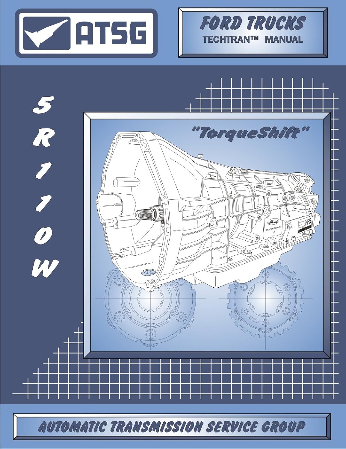
Three signals, two sensors
The 5R110W reads three shaft speeds, but you only have two sensor housings to deal with. Per ATSG's TorqShift manual and Transmission Digest's unit overview:
- Turbine shaft speed (TSS). Reads the teeth on the coast clutch input hub. That is input speed, the number the PCM compares against engine rpm to see converter slip.
- Intermediate shaft speed (ISS). Reads the adjacent overdrive ring gear teeth. It lets the PCM see what the front of the geartrain is doing separately from the input, which it uses to judge clutch apply and release timing.
- Output shaft speed (OSS). Reads a dedicated set of teeth on the park gear, separate from the teeth the pawl uses. ATSG lists vehicle speed, shift scheduling and TCC among its uses. Note that the PCM's separate "VSS" input on these trucks comes from the ABS system, not the OSS (see the codes section below).
TSS and ISS live in one housing mounted on the outside of the case. Both read 30 teeth per revolution. OSS is a separate sensor in the extension housing. All three are Hall effect sensors, and ATSG and TD both state they need a 12-volt supply and a ground. That matters if you work on newer Fords too: Sonnax's 10R-series write-up lists those speed sensors on a 9-volt supply. Know which truck you are on before you judge a reference voltage.
One detail on OSS that explains some odd symptoms: ATSG notes it is bi-directional. The tone wheel has three different width spaces between its teeth, and the PCM reads the difference in pulse width to tell which way the shaft is turning. A damaged tone wheel or a weak signal can confuse direction as well as speed.
What the PCM does with them
ATSG says the TSS/ISS input is used to determine line pressure, shift timing and TCC operation, and the OSS feeds vehicle speed, shift scheduling and TCC. On a clutch-to-clutch unit that is nearly everything. The PCM knows a shift is finished when the measured ratio (turbine speed divided by output speed) lands on the target gear ratio, and it adapts pressure based on how long that took.
For reference, ATSG gives the 5R110W ratios as 3.09 first, 2.20 second, 1.54 third, 1.00 fifth in hot mode or 1.09 fourth in cold mode (below 5°F on the TFT), 0.71 sixth, and 2.88 reverse. If the speed inputs are wrong, the calculated ratio is wrong, and the PCM either sets a ratio error or decides a clutch is slipping when it is not.
Symptoms by sensor
TSS or ISS failing
- Harsh, late or erratic shifts, often worse warm than cold.
- No converter clutch apply, or TCC that applies and drops out. The PCM cannot measure slip without turbine speed.
- Firm engagements as the PCM raises line pressure to protect the unit.
- Check engine light with input or intermediate speed codes, sometimes with ratio or TCC slip codes riding along.
OSS failing
- Shift timing and converter lockup that do not match road speed.
- A speedometer or cruise problem is possible, but on these trucks a dead speedometer with the ABS light on points more often to the rear axle speed sensor than to the OSS.
- Shift points that make no sense for road speed, including downshifts at speed.
- Output speed codes, and on many trucks a string of gear ratio codes as the PCM's math falls apart.
Gears Magazine's sensor failure article puts it plainly: speed sensor failures usually cause no shifts or failsafe operation, and sometimes codes are present, sometimes not. An intermittent dropout that lasts a fraction of a second can upset a shift without ever meeting the PCM's code-setting criteria. That is why a no-code shift complaint on a TorqShift still gets its speed signals checked.
The codes
ATSG's 5R110W code chart lists the speed sensor faults in plain terms: loss of TSS signal during normal operation, no TSS signal detected, noisy TSS signal, and the same three conditions for OSS, plus a gear ratio error. The generic OBD-II numbers you will actually see on the scan tool:
| Code | ATSG 5R110W description | First thing to check |
|---|---|---|
| P0715 / P0718 | TSS signal lost during operation / noisy TSS signal | Dropping or noisy TSS signal, connector, harness chafe |
| P0717 | No TSS signal detected | 12 V supply and ground at the TSS/ISS connector |
| P0720 / P0721 | OSS signal lost during operation / noisy OSS signal | OSS connector, tone wheel teeth, harness at the extension housing |
| P0722 | No OSS signal detected | OSS supply, ground and signal wire continuity |
| P0500 / P0503 | Vehicle speed sensor lost / intermittent (ATSG: VSS signal through the SCP link from ABS) | Not a transmission sensor. Rear axle speed sensor, its harness, the tone ring and the ABS module |
| P0791 / P0793 / P0794 | Insufficient ISS input / no ISS input / ISS signal intermittent | ISS signal wire; TSS and ISS share one housing, so check both |
The chart has no P0716 for this unit, so a P0716 on a TorqShift truck deserves a second look at which module and transmission the scan tool thinks it is talking to. For P0791, Ford's 2004 6.0L diesel OBD summary spells out the test: in any forward range, with the engine above 3000 rpm (above stall), or turbine shaft at 800 rpm, or output shaft at 500 rpm, or 10 mph, the code sets when the ISS reads under 250 rpm for 5 seconds with positive driving torque. The full ISS walk-through is in our 5R110W P0791 guide.
P0500 trips up a lot of TorqShift diagnosis. Ford's 2010 OBD system summary says in its 5R110W section that "the vehicle speed signal is provided from the ABS system to the PCM," and the 2004 6.0L diesel summary says the same and notes P0500 is used on 6.0L heavy-duty F-Series and Excursion. Per the 2010 summary, P0500 sets when the engine is above converter stall in a drive range but the VSS reads under 1-5 mph for 5 seconds. So P0500 without any P07xx speed codes is an ABS-side fault, and a new OSS will not fix it. The full walk-through is in our 5R110W P0500 guide.
A TSS code and an ISS code set together almost always mean something they share: the combined sensor itself, the shared 12-volt reference, the shared ground, or the connector. A single signal code with the other channel reading normally points at that signal wire.
Diagnosis: sensor, wire or something else
1. Scan data first
Watch TSS, ISS and OSS rpm on the scan tool in park, then in gear rolling. In park at idle, TSS should follow engine rpm closely (the converter is unloaded) and OSS should read zero. Rolling in a known gear, divide TSS by OSS and compare it with the ratios above. Sonnax uses the same method on the Ford 10R: compare calculated ratios to the spec chart to find which sensor is lying. Graph the PIDs rather than reading numbers, but remember Gears' warning that scan data is averaged and can hide a short glitch.
2. Supply and ground at the connector
ATSG's pinout for the TSS/ISS connector: pin 1 reference voltage (pink/white), pin 2 ground (black/white), pin 3 TSS signal (green/white), pin 4 ISS signal (gray/orange). The OSS connector is pin 1 reference (pink/white), pin 2 OSS signal (blue/yellow), pin 3 ground (black/white). At the PCM, ATSG lists TSS signal on pin 29, ISS on pin 27 and OSS on pin 28 of the transmission connector. Check for battery-level reference with key on, and voltage-drop the ground under load. A dead reference kills every sensor on that circuit, which is a quick way to tell a supply problem from a sensor problem.
3. Scope the signal
This is the test that actually proves a Hall effect sensor. Gears' "Advanced Speed Sensors" piece describes what a good one looks like: a square wave that drops to near zero, around 0.1 V, and pulls up cleanly to its pull-up voltage, with frequency rising as the shaft speeds up. Scope at the PCM end if you can, so you see what the module sees.
Wayne Colonna of ATSG, writing in Transmission Digest about the 5R110W and Aisin units, points out why Hall sensors make wiring faults easy to spot: the sensor is designed to pull the signal down to about 0.5 V, not to zero, on a roughly 0.5-to-5-volt pulse. When his signal wire rubbed through its insulation against metal, the scope showed the low side dropping from 0.5 V to a flat 0 V and back. That dead-zero dip is a short to ground in the harness, not a bad sensor. A clean square wave that just stops, then comes back, points at the sensor or a connector.
4. Ohmmeter, with a grain of salt
ATSG publishes 325-485 ohms at 70°F between terminals 1 and 3 (TSS) and 1 and 4 (ISS), and between 1 and 2 on the OSS. An open reading condemns the sensor. A reading in range does not clear it. Gears notes that a Hall effect sensor has an integrated circuit inside, so resistance checks do not tell you whether it switches. Use the ohmmeter to catch the obvious, then scope it.
5. Pull the sensor and look
Hall sensors are magnetic at the tip, and a TorqShift with clutch wear sheds fine metal. A tip packed with fuzz can weaken the signal. If the tip is loaded with debris, clean it, but also ask why there is that much metal in the pan. On the OSS side, ATSG's teardown calls for inspecting the park gear and speed sensor rotor and replacing it as needed, so a chipped or damaged tooth on that rotor belongs on the list when OSS reads erratic but the sensor and harness test good.
Shop the part for this fix: 5R110W input/output speed sensor set
OEM-spec TSS/ISS and OSS sensor set (3C3Z-7H103-AA) for the 5R110W, for when the supply, ground and harness check out and the scope shows the sensor dropping out.
See the speed sensor set at CoreTransmissionPartsReplacing them
Both sensors are external, so neither one needs the pan dropped. Per ATSG:
- Unplug the connector and clean around the sensor before you pull it, so dirt does not fall into the case.
- Remove the single retaining bolt and work the sensor out. Old O-rings harden and stick, so twist rather than pry against the tip.
- Install a new O-ring and lubricate it with transmission fluid.
- Seat the sensor fully by hand and torque the bolt to 9 N-m (80 in-lb). It is a small bolt into aluminum; do not guess with an impact.
- Plug in, clear codes, and road test while graphing TSS, ISS and OSS.
If you lost fluid during the swap, top off with the right fluid. The 5R110W launched on MERCON SP, and Ford's current Motorcraft ATF quick reference chart lists the 5R110 TorqShift under MERCON LV with authorization to back-service with MERCON LV. After any repair that changed shift feel, ATSG's relearn applies: fluid at 130°F on the TFT, then five each of Park-to-Reverse, Drive-to-Reverse, Reverse-to-Drive and Neutral-to-Drive engagements, five seconds apart.
When a new sensor does not fix it
If the code comes right back with a new sensor, go back to the harness. The sensor pigtails run along the transmission and frame on a truck that sees heat, water, salt and heavy towing, and that is hard on terminals. Look for pushed-back terminals, green corrosion, and any spot where the harness can touch the case, a bracket or the crossmember. On 6.0L trucks, remember that a fluid-contaminated PCM connector can throw a spread of unrelated transmission codes; our 5R110W pressure control solenoid post covers the diesel-in-the-harness case in detail.
Range sensor codes, speed sensor codes and a no-start all at once point at the shared reference voltage. Per Transmission Digest's May 2011 Tech/Talk, PCM connector "B" pin 1 feeds the range sensor and the turbine, intermediate and output speed sensors, and inside the PCM it is tied to the electronic fan clutch speed sensor reference (connector "C" terminal 46). A shorted fan clutch speed sensor can drag that voltage down and set P0706, P0708, P1705 and speed codes from P0715 to P0722. Their test: unplug the fan clutch connector on the driver side of the fan shroud, clear codes and drive. If the codes stay away, replace the fan clutch speed sensor, not a transmission sensor.
If all three signals scope clean and the calculated ratio still does not match the commanded gear, the sensors are telling the truth and the clutch really is slipping. That is a hydraulic or friction problem, and it is time for a pressure gauge, not another sensor.
The short version
- TSS and ISS share one housing on the case; OSS is in the extension housing. All are 12-volt Hall effect sensors.
- TSS/ISS feed line pressure, shift timing and TCC. OSS feeds vehicle speed, shift scheduling and TCC.
- TSS and ISS codes together mean the shared sensor, reference, ground or connector.
- Scope the signal: about 0.1-0.5 V low, clean pull-up high. A dip to 0 V is a wire shorting to ground.
- 325-485 ohms only proves the sensor is not open.
- New O-ring, 9 N-m (80 in-lb) on the bolt, MERCON LV to top off.
Need parts for this job?
If the sensors check good and the problem is inside the unit, our 5R110 parts page has solenoid kits, valve bodies, pumps and rebuild kits for the TorqShift, all on our own checkout.
FAQ
Where are the speed sensors on a 5R110W?
There are two sensor housings. The turbine shaft and intermediate shaft sensors share one housing that bolts to the outside of the transmission case, and the output shaft speed sensor bolts into the extension housing. Both are held by a single bolt torqued to 9 N-m (80 in-lb) and seal with an O-ring.
What are the symptoms of a bad 5R110W speed sensor?
A failing turbine or intermediate sensor usually shows up as harsh or erratic shifts, a converter clutch that will not apply, and a check engine light. A failing output sensor adds shift points and converter lockup that make no sense for road speed. A dead speedometer with the ABS light on and P0500 points to the rear axle speed sensor instead, because the PCM gets vehicle speed from the ABS system on these trucks. An intermittent sensor can do all of this with no code stored.
Can you test a 5R110W speed sensor with an ohmmeter?
ATSG lists 325-485 ohms at 70 degrees F across the reference and signal terminals, so an ohmmeter will catch a sensor that is open. It will not prove a good one. These are Hall effect sensors, and the only real test is a scope or graphing meter watching a clean square wave on the signal wire with the truck moving.
What voltage does the 5R110W speed sensor use?
ATSG and Transmission Digest both describe the 5R110W TSS/ISS and OSS as Hall effect sensors that need a 12-volt supply and a ground. The signal they send back to the PCM is a digital on-off square wave whose frequency rises with shaft speed. Later Ford 10-speed units run their speed sensors on 9 volts, so do not carry that number over.
Is one speed sensor code enough to replace the sensor?
No. The sensors sit at the end of a harness that runs along the frame and transmission, and a chafed signal wire shorting to ground sets the same code as a dead sensor. Check the supply and ground at the connector, look at the signal on a scope, and inspect the harness before buying the part.
Related guides
- 5R110W P0791: Intermediate Shaft Speed Sensor Causes & Fix
- 5R110W Pressure Control (EPC) Solenoid Symptoms
- 5R110 Shift Solenoid Symptoms and Testing
- 5R110W Limp Mode Causes
- 5R110W Harsh Shift Causes
- 5R110W Common Problems and Fixes
Sources
- ATSG, Ford 5R110W (TorqShift) technical manual (2004). Backs the TSS/ISS/OSS locations, tooth targets, 30 teeth per revolution, 12-volt Hall effect design, OSS bi-directional tone wheel, sensor connector and PCM pinouts, 325-485 ohm specs, the speed sensor code descriptions, gear ratios, 9 N-m (80 in-lb) sensor bolt torque, park gear/rotor inspection and the engagement relearn. ATSG manual (PDF)
- Transmission Digest, "Ford 5R110W ('TorqShift')." Backs TSS/ISS as 12-volt Hall effect sensors in one housing reading the coast clutch hub and overdrive ring gear, their use for line pressure, shift timing and TCC, and the OSS reading the park gear. transmissiondigest.com
- Transmission Digest, "May 2011 Issue" Tech/Talk, "5R110W: Transmission-range-sensor/speed-sensor faults or no start." Backs the shared PCM reference to the range sensor and TSS/ISS/OSS, its internal link to the fan clutch speed sensor reference, the P0706/P0708/P1705 and P0715-P0722 code spread, and the unplug-and-drive test. transmissiondigest.com
- Transmission Digest, Wayne Colonna (ATSG), "An Interesting 'Spin-off' of a Hall-Effect Speed Sensor." Backs the 0.5-to-5-volt Hall signal, the 0.5 V pull-down, and the scope signature of a signal wire chafed through and shorting to ground. transmissiondigest.com
- Gears Magazine (ATRA), "Advanced Speed Sensors Part 1." Backs the scope test (switching to about 0.1 V and pulling up cleanly), the limits of a DVOM on a running sensor, and why resistance checks do not prove a Hall effect sensor. gearsmagazine.com
- Gears Magazine (ATRA), "Sensing Problems: A Look at Common Sensor Failures." Backs speed sensor failures causing no shifts or failsafe operation with or without codes, intermittent dropout and noise, and scan data averaging hiding glitches. gearsmagazine.com
- Sonnax, "Diagnosing Ford 10R60/10R80/10R140 Series Speed Sensor Issues." Backs the 9-volt supply on Ford 10R speed sensors and the method of comparing calculated gear ratios to spec to find a bad speed input. sonnax.com
- Ford Customer Service Division, Motorcraft ATF quick reference chart. Backs MERCON LV for the 5R110 TorqShift and back-service authorization. Ford ATF chart (PDF)
- Ford Motor Company, 2010 MY OBD System Operation Summary for Gasoline Engines, 5R110W and vehicle speed sections. Backs the ABS-supplied vehicle speed signal on the 5R110W and the P0500 threshold (VSS under 1-5 mph for 5 seconds above converter stall). Ford OBD summary (PDF, archive.org)
- Ford Motor Company, 2004 MY OBD System Operation Summary for 6.0L Diesel Engine. Backs the 5R110W speed sensor rationality checks, the P0791 ISS functional check (under 250 rpm for 5 seconds), and P0500 use on 6.0L heavy-duty F-Series and Excursion. Ford 6.0L OBD summary (PDF, archive.org)