P0715 on a TorqShift is one of those codes that gets parts thrown at it. The scan tool says "input/turbine speed sensor," the counter guy has the sensor in stock, and the truck leaves with a new one and the same harsh shifts. Sometimes that works. Often the code comes back within a week, because the sensor was never the problem.
This post is narrower than our general 5R110W speed sensor symptoms guide. It covers one code: what the PCM actually has to see to set P0715 on a 5R110W, how it differs from its two sister codes, what the code pattern tells you before you pick up a meter, and the order I check things so the truck gets fixed once. Specs come from the ATSG TorqShift manual, Transmission Digest, Gears (ATRA) and Ford, all listed under Sources.
What P0715 means on this unit
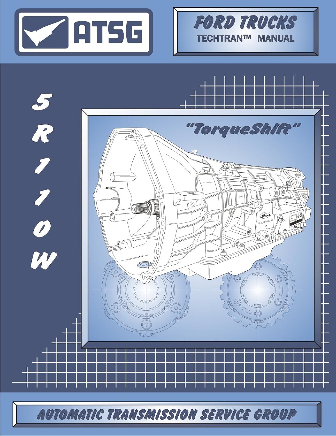
The 5R110W showed up in model year 2003 in the Super Duty and Excursion with the 6.0L diesel (Transmission Digest's unit overview), and it later went behind the 6.8L V10 and the 6.4L diesel. It is a clutch-to-clutch unit. There are no shift valves behind the shift solenoids, so the PCM times every clutch apply and release off shaft speeds. Input speed comes from the turbine shaft speed (TSS) sensor.
The ATSG 5R110W diagnostic chart splits turbine speed faults into three codes, and the wording matters:
| Code | ATSG description | What it points at |
|---|---|---|
| P0715 | PCM detected a loss of TSS signal during normal operation | The signal was there, then it went away. Think intermittent: a connector, a chafed wire, heat, or a sensor dropping out. |
| P0717 | PCM has not detected a TSS signal | No signal at all. Think open circuit, no reference voltage, or a dead sensor. |
| P0718 | PCM has detected a noisy TSS signal | Signal present but dirty. Think interference, a poor ground, or a damaged tone target. |
So a stored P0715 by itself tells you the circuit worked at some point during that drive cycle and then quit. That is the opposite of a sensor that is simply dead. A dead sensor more often shows up as P0717. When a truck comes in with P0715 only, I start looking for something that moves, heats up, or gets wet.
What the TSS reads and why the truck shifts badly without it
Per ATSG and Transmission Digest, the TSS and the intermediate shaft speed (ISS) sensor share one housing that bolts to the outside of the case. The TSS reads teeth on the coast clutch input hub. The ISS reads the adjacent overdrive ring gear. Both see 30 teeth per revolution. Both are Hall effect sensors that need a 12-volt supply and a ground, and both send a digital signal the PCM uses to set line pressure, shift timing and torque converter clutch (TCC) operation.
Take away input speed and the PCM can no longer measure slip across the converter, and it can no longer tell when a shift has finished. It knows a shift is done when the ratio of turbine speed to output speed matches the target gear. Without that number it falls back to a default strategy. Expect firm or harsh shifts, a converter that will not lock, and on some trucks a default-gear limp mode. Gears' Keith Clark puts it plainly: speed sensor failures usually mean no shifts or failsafe operation, and codes may or may not be set.
Read the code pattern before you touch a meter
The pinout is the reason the code pattern is useful. ATSG's 5R110W wiring schematic shows one reference voltage circuit (PCM connector "B" pin 1, pink/white) feeding both sensor housings, and one ground circuit (pin 22, black/white) shared by both. The signals come back on separate wires: TSS on pin 29 (green/white), ISS on pin 27 (gray/orange), OSS on pin 28 (dark blue/yellow).
- P0715 alone. The problem is on the TSS signal path only: the sensor itself, the green/white signal wire, or that terminal at either connector. The shared supply and ground are probably fine, because the OSS kept working.
- P0715 with P0720/P0721/P0722 (output speed codes). Two sensors in two different housings lost signal on the same drive. Look first at the shared supply and ground, or at the PCM connector. Two sensors rarely fail on the same day.
- P0715 with pressure control or solenoid codes. Now you are looking at something that hits a whole connector or the PCM. Transmission Digest documented a 2005 F-350 6.0L with a 5R110W that set pressure control A codes. A leaking water-in-fuel sensor had soaked the C138E connector on the left frame rail, and diesel fuel wicked up the harness into the PCM, which held about a pint of fuel. The fix was a PCM, a water-in-fuel sensor (6C3Z-9C264-A), and a separator drain. That case did not involve P0715, but it shows how far contamination can travel in these harnesses. On a 6.0L that throws random speed and solenoid codes together, check that connector before you condemn anything on the transmission.
- P0715 with ratio codes (P0730) and a slipping feel. Be careful here. A real slip and a lost input signal can look alike on paper. The scan data in the next section separates them.
Scan data checks with the engine running
Before unplugging anything, pull up engine rpm and the TSS, ISS and OSS rpm PIDs on a graphing scan tool and drive the truck.
- Converter locked, steady cruise. With the TCC applied, turbine speed should track engine rpm almost exactly. If engine rpm is a steady 1,700 and TSS is jumping between 1,700 and zero, the signal is dropping out. If both sit together, the sensor is reading at that moment.
- Calculated ratio. Divide TSS by OSS and compare it to the gear ratios Transmission Digest lists for the TorqShift: 1st 3.09, 2nd 2.20, 3rd 1.54, 5th 1.00, 6th 0.71 (and 4th 1.09 when the unit is in cold mode below 5 degrees F). A ratio that matches the gear and holds steady means the input signal is good and any slip complaint is mechanical. A ratio that spikes to nonsense or drops to zero for an instant points back at the signal.
- Watch for the dropout trigger. Note whether the dropout follows heat, a bump, or a full-lock turn. That tells you where to look on the harness.
Keep one limit in mind. Clark notes that scan tool graphs are averaged, so a glitch that lasts a few milliseconds can disappear between data frames. A clean scan graph does not clear the circuit. If the code keeps coming back and the scan data looks fine, move to a scope.
Electrical checks, in order
1. Connector and harness first
Unplug the TSS/ISS sensor connector and look. Check for green corrosion, pushed-back terminals, fluid or fuel in the connector body, and a lock tab that does not latch. Then follow the harness from the sensor back along the transmission and frame. P0715 is a "lost it while driving" code, so you are hunting a wire that rubs on the case, an exhaust heat shield, or a crossmember when the drivetrain twists under load.
2. Reference voltage and ground at the sensor connector
Key on, sensor unplugged. Per ATSG the sensor connector is pin 1 reference voltage (pink/white), pin 2 ground (black/white), pin 3 TSS signal (green/white), pin 4 ISS signal (gray/orange). You want battery-level reference voltage on pin 1, since this is a 12-volt Hall sensor, and a clean ground on pin 2. Load-test the ground rather than reading it with no current flowing. Gears' Sean Boyle points out that excess voltage drop on a Hall sensor ground can lift the low side of the signal, and the module may misread it.
3. Signal wire end to end
Check continuity from sensor connector pin 3 to PCM connector "B" pin 29, then check that same wire for a short to ground and a short to voltage. Wiggle the harness while you watch the meter. A wire that reads good sitting still and opens when you flex it is your P0715.
4. Scope the signal at the PCM
Clark recommends connecting the scope at the control module so you see what the module sees. A good Hall signal is a clean square wave that drops to near zero and pulls up sharply. Its amplitude stays constant and its frequency rises with shaft speed. Boyle's trick for intermittents works well here: warm the sensor with a heat gun and tap lightly on the housing while watching for the pattern to break up. A DVOM alone cannot do this job. It averages the switching and shows you a steady number while the signal underneath is falling apart.
5. The ohmmeter, with limits
ATSG lists 325-485 ohms at 70 degrees F between TSS terminals 1 and 3 (and the same range for ISS terminals 1 and 4). An open reading condemns the sensor. A reading in range does not clear it. Boyle explains that the integrated circuit inside a Hall sensor makes resistance readings unreliable as a pass test. Use the number to rule a sensor out, never to rule one in.
Shop the part for this fix: 5R110W input/output speed sensor set
OEM-spec TSS/ISS and OSS sensor set (3C3Z-7H103-AA) for the 5R110W, for when the connector, supply, ground and signal wire all check good and the scope shows the sensor itself dropping out.
See the speed sensor set at CoreTransmissionPartsReplacing the sensor
The TSS/ISS housing mounts on the outside of the case, so this is not a teardown job. Clean the area around the sensor before you pull it so dirt does not fall into the bore. Look at the tip when it comes out. Metallic fuzz stuck to the magnet is worth noting, because it can distort the signal, and it also tells you something about what is happening inside the unit.
- New O-ring on the sensor, lubricated with clean ATF.
- Seat it by hand and torque the retaining bolt to 9 N-m (80 in-lb), per the ATSG assembly procedure. This is a small bolt in an aluminum case, so do not guess with an impact.
- Check the fluid level hot and top off with the correct fluid. Ford's Motorcraft ATF chart authorizes MERCON LV for the 5R110 TorqShift, including back-servicing early units. The 2009 Super Duty owner guide lists 17.5 quarts (16.6 L) for the 5R110 including the cooler, as an approximate dry-fill figure. Set the actual level on the dipstick's operating range, not by pouring in a number.
- Clear codes and drive through every gear with the converter locking. Watch the TSS PID against engine rpm the whole time.
When a new sensor does not fix P0715
If the code returns with a new sensor and a clean harness, go back to the pattern. Did other codes come with it this time? Was the dropout tied to heat or to a bump? Three things are left.
- PCM connector and the PCM. Inspect connector "B" for corrosion or contamination. On a 6.0L, rule out the fuel-wicking problem Transmission Digest documented. Replace the PCM only after the signal on a scope looks clean at the PCM pin while the code still sets.
- The tone target. The TSS reads the coast clutch input hub. A damaged hub, or excessive end play that moves the target away from the sensor, can produce a weak or noisy signal that no external part will fix. That is a teardown finding, and it usually comes with P0718 or ratio codes rather than P0715 alone.
- A real mechanical slip. If your ratio math showed slip with a clean input signal, the code was a side effect. The problem is clutches, pressure or the valve body. Our 5R110W limp mode guide covers that path.
Need parts for this job?
If the sensor checks out and the diagnosis points inside the unit, our 5R110 parts page has solenoid kits, valve bodies, pumps and rebuild kits for the TorqShift, all on our own checkout.
FAQ
What does P0715 mean on a 5R110W?
Per the ATSG 5R110W code chart, P0715 means the PCM detected a loss of the turbine shaft speed (TSS) signal during normal operation. The signal was present and then dropped out. A signal that is never there sets P0717, and a noisy signal sets P0718.
Can I drive a 5R110W with a P0715 code?
Short trips are usually possible, but expect harsh shifts, no converter lockup and possibly a limp mode, because the PCM uses turbine speed for line pressure, shift timing and TCC control. Towing or working the truck hard in that state adds heat and clutch wear, so diagnose it before the truck goes back to work.
Do you have to drop the transmission to replace the 5R110W turbine speed sensor?
No. The turbine and intermediate shaft speed sensors share one housing that bolts to the outside of the case. It comes out with one bolt, takes a new O-ring, and the bolt torques to 9 N-m (80 in-lb) per ATSG.
Why does P0715 come back after replacing the sensor?
Because the sensor was not the fault. P0715 is a dropout code, so the usual cause is a connector, a chafed signal wire, or a shared reference or ground problem. If P0715 sets along with output speed codes, check the shared supply, ground and PCM connector before buying another sensor.
Related guides
- 5R110W Input/Output Speed Sensor Symptoms
- 5R110W TCC Lockup Explained
- 5R110W Limp Mode Causes
- 5R110W Harsh Shift Causes
- 5R110W Common Problems and Fixes
Sources
- ATSG, Ford 5R110W (TorqShift) technical manual (2004). Backs the P0715/P0717/P0718 descriptions, the TSS/ISS tooth targets and 30 teeth per revolution, the 12-volt Hall effect design, the sensor connector and PCM connector "B" pinouts (reference pin 1, ground pin 22, ISS 27, OSS 28, TSS 29), the 325-485 ohm specs and the 9 N-m (80 in-lb) sensor bolt torque. ATSG manual (PDF)
- Transmission Digest, Dale England, "Ford 5R110W ('TorqShift')" (2004). Backs the 2003 introduction in the 6.0L Super Duty and Excursion, TSS/ISS location and function, cold/hot mode, and the 3.09/2.20/1.54/1.09/1.00/0.71 gear ratios. transmissiondigest.com
- Transmission Digest, "Ford 5R110W PCM Fault Codes." Backs the 2005 F-350 6.0L case of diesel fuel wicking through the C138E connector into the PCM, and the PCM plus water-in-fuel sensor 6C3Z-9C264-A repair. transmissiondigest.com
- Gears Magazine (ATRA), Sean Boyle, "Advanced Speed Sensors Part 1" (April 2024). Backs Hall sensor supply and ground checks, ground voltage drop lifting the signal low, DVOM limits, the heat-and-tap intermittent test, and why resistance readings do not prove a Hall sensor. gearsmagazine.com
- Gears Magazine (ATRA), Keith Clark, "Sensing Problems: A Look at Common Sensor Failures." Backs failsafe/no-shift behavior with or without codes, intermittent dropout and noise, scan data averaging, and scoping at the module. gearsmagazine.com
- Ford Customer Service Division, Motorcraft automatic transmission fluid quick reference chart. Backs MERCON LV for the 5R110 TorqShift, including back-service authorization. Ford ATF chart (PDF)
- Ford Motor Company, 2009 F-250/350/450/550 Owner's Guide (archived copy). Backs the 17.5 qt (16.6 L) 5R110 capacity including the cooler, Motorcraft MERCON LV, and setting the level by the dipstick. Ford owner guide (PDF, archive.org)