Two complaints land on the same Aisin unit constantly and get treated as two different jobs. Harsh comes in as "it bangs into second." Delayed comes in as "I put it in Drive and count to two before it grabs." Same underlying question either way: is the transmission commanding the wrong pressure, or is a worn bore losing the pressure it commanded?
Answer that before you pull anything. On the Aisin Warner front-drive family — AW55-50SN and 55-51SN, badged AF23/AF33 by GM and RE5F22A by Nissan — the valve body accounts for most of the unit's issues, and it is testable at the pressure taps with the transmission still in the car.

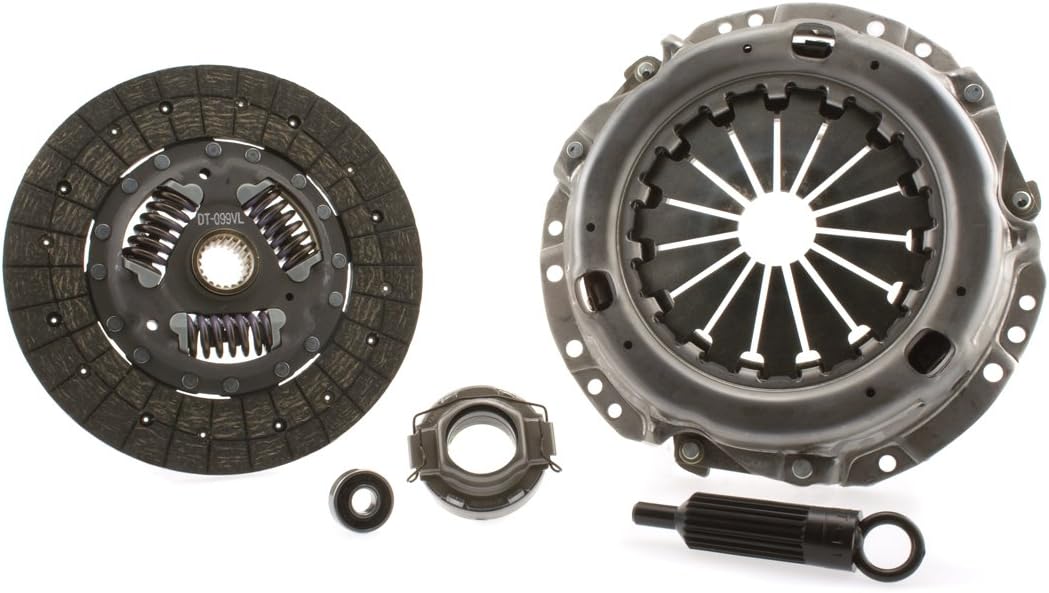
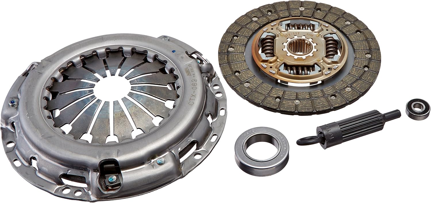
Know which unit is on your lift
The AW55-50SN ran from 2000 to 2015 and shows up as the AF33 in the Chevrolet Equinox and Captiva, Pontiac Torrent and Saturn Vue, plus Volvo, Saab and Nissan applications. A near-identical valve body will physically bolt to a GM, Volvo, Saturn, Nissan, Saab, Opel or Renault case, which is the trap. Sonnax counts six different shift solenoids across the family, most of which will fit the wrong location, and some positions were normally open in one application and normally closed in another — on a GM-to-Volvo swap, the #2 solenoid is normally open on the GM unit and has to be the Volvo normally closed part.
The three linear solenoids — SLT, SLS and SLU — are each calibrated to the valve they control, so swapping an SLT or SLS between cores without readjusting it is not an acceptable repair. A good share of harsh-shift comebacks on this unit are a good valve body with a mismatched solenoid bolted to it.
Step one: fluid and level
Low fluid and overfill both produce erratic pressure and poor linear solenoid control, and if the TCM sees enough of it, it moves to a high-pressure strategy that makes every shift harsh on its own. You can chase valve bores for a week on a unit that is a quart low.
The spec is JWS 3309, the Aisin Warner fluid also carried as Toyota Type T-IV. Mobil ATF 3309 is the usual shelf answer; its published data lists GM 9986195, Toyota T-IV, Ford WSS-M2C924-A and Audi G-055-025-A2, with kinematic viscosity of 33 mm2/s at 40 C, 7.1 mm2/s at 100 C and a viscosity index of 181. Viscosity is not a footnote here: this unit uses slip-controlled converter clutch apply and the SLU meters that slip through the fluid, so a thicker generic ATF changes the modulation, not just the feel.
One warning that costs people whole transmissions: the 27 mm nut on top of the case is not a fill plug or a pressure tap. It is the B-4 band anchor, and backing it out means recapturing the band — pulling the servo at best, the whole unit at worst. Every real pressure plug here has a 12 mm head.
Step two: read the four pressure curves
Every circuit has a port. Put transducers or a good gauge set on them and drive it.
C-1 forward clutch
C-1 is the input clutch, so its curve is the baseline everything else gets compared against. Normal is zero in Park, a step to about 25 psi as Drive is selected, up to 50 psi within half a second, held until you accelerate, then following load to a maximum near 200 psi.
The most useful single tell on this unit: if C-1 jumps straight to 160 psi the instant you select Drive and reaches 200 psi during a shift, the TCM has commanded a pressure rise and you are likely in a code or failsafe condition, not a mechanical fault. Verify with SLT current, then pull codes and check the electrical side before you touch the valve body.
SLT line rise
SLT is the torque-sensitive line rise control, and it should track engine load like it is wired to the MAF signal: roughly 5 to 6 psi in Drive at idle, rising with throttle and load to a maximum around 78 to 80 psi. Watch for a curve that hangs at a fixed value instead of tracking load. A hanging SLT output means the solenoid or the valves it acts on are worn or contaminated.
B-4 servo apply
The B-4 tap is at the top of the case, in line with the linkage bolts. Memorize this one: B-4 should follow C-1 and never sit more than 10 psi below it in third. If B-4 is the low one, suspect the servo feed tube O-rings. If C-1 is the low one, you have a bigger problem, because a fluctuating input clutch produces both delayed engagement and flare shifts.
Lube pressure and cooler flow
The lube tap sits between the secondary regulator valve and the mainshaft bushings. At 150 F, normal lube is 5 psi in Drive and 8 psi in Reverse; cold, near -10 F, it can run as high as 30 psi. Lube that starts low and stays at zero points at low pump output, a worn regulator bore, or bad bushings. Cooler flow in Drive with the converter clutch released is about 1.3 gpm, dropping to 0.7 gpm on apply. Lube volume here is low compared to other units, and the converter can stay fully applied at low speed under high load, which cooks the fluid.
Delayed engagement: where the pressure goes
A delayed Drive engagement, especially one that needs extra throttle to catch, has three usual homes.
SLT sitting at zero. Zero SLT in Drive causes a Neutral-to-Drive delay, often with a bang when it finally engages, plus long shifts and low cooler flow. It sounds like three complaints and it is one cause.
Neutral relay valve bore wear. Wear here leaks the forward clutch circuit and drops C-1 apply pressure. Sonnax lists the symptom pair as delayed Forward plus increased throttle required for engagement, and sells an oversized valve and spring (59947-35K, tooling F-59947-TL34 and VB-FIX). If the complaint is those two sentences, test that bore first.
Pressure regulator and boost valve wear. This bore wears at multiple points and the location tells you the symptom. Wear at the balance end drives harsh shifts, high line pressure and converter apply/release problems; wear elsewhere gives soft shifts and low line pressure. Boost sleeve wear is its own diagnosis: it reduces the ability of line pressure to rise on TCM command, so line rise is slow, shifts go late, and late shifts generate gear ratio codes. Left alone it delays or slips Reverse and eventually burns the low reverse B-3, the 1-2 reverse B-5 band, or the direct clutch C-2. The oversized kit is 59947-12K — note the OE retainer step location before you pull it and match it on the replacement valve.
The SLT air test, before the valve body comes out
Pressurize the SLT port with 80 to 100 psi of shop air and watch for fluid pushed out as a visible leak. The spots that leak are the steel side cover, the SLT accumulator, and the B-1 and C-1 control valves. A major leak, or a combination of small ones, produces delayed engagement and flare upshifts. Five minutes, and it tells you whether the rest of the day involves a valve body.
Harsh shifts: accuse the right solenoid
All the solenoids in this family measure 5.0 to 5.6 ohms and run at 300 Hz. SLT is normally open and inverse-acting — low current produces higher pressure — in roughly a 15 to 40 percent duty range. Knowing which direction that relationship runs keeps you from misreading a scan tool. Past that, separate SLT from SLS:
- High SLT (20 psi in Drive instead of 5 to 6): long 2-3 or a bind-up on 2-3, a 3-2 coast-down bump, harsh forward engagements, a short converter clutch apply ramp with lost modulation slip at low speed, reduced lube pressure and cooler flow. High SLT together with a harsh Reverse points specifically at secondary regulator bore wear near the spring spool.
- High SLS: harsh Reverse, harsh 1-2, harsh 2-3 with an end bump, loss of converter clutch apply, raised C-1 clutch pressure, 3-2 flare or bang. SLS runs 0 to 78 psi and acts only on the shift pressure control plunger to set clutch feed rate by engine load.
- Low SLS: soft upshifts, a low-speed 2-3 flare, slight rpm flare on 3-4 and 4-5.
The distinction that saves you a teardown: SLS does not affect forward engagement. If the complaint includes a delayed or harsh Neutral-to-Drive engagement, SLS is not your solenoid. That belongs to SLT and the C-1 circuit.
Then there is the solenoid modulator valve, which feeds all three linear solenoids and caps their maximum pressure. When that bore wears the pattern goes broad — low line pressure, 2-3 flare, no 3rd, 4th or 5th, delayed Forward, 5th gear only, no lockup. It behaves like a bad GM actuator feed circuit, and it is worth testing early precisely because it mimics several faults at once.
The 2-3 flare and the 3-2 bang: the signature job
If you have not had an AW55-50SN in with an intermittent 2-3 flare or a harsh 3-2 downshift yet, you will. It arrives wearing a Nissan, Volvo, Saab, GM, Saturn, Renault or Opel badge, usually with P0780 or P0785, sometimes P0745.
The mechanics make the symptom obvious. The 2-3 upshift needs the B-4 band applied and the B-5 brake clutch released, correctly timed, which means matching a changing drum speed to a clutch release. The 3-2 runs backward: B-4 releases, B-5 applies. Coasting or in a turn, the axles are loading and driving the 4-5 drum, so the band force needed to hold it varies with load, and timing that is perfect at one load is early or late at another. When the TCM, solenoids and valves let B-4 release before B-5 applies, the unit is momentarily in neutral. That is your coast-down or maneuver bang.
In the vehicle you can alter the servo pin to land 0.095 to 0.110 in. of travel, or install the updated servo cushion spring. That often reduces severity or frequency but is generally not a complete fix. Volvo answered it with an updated servo and cover, documented in Volvo bulletin 43-37 dated 2-25-03.
The real fix is usually in the bore, and the most overlooked one on this unit is the B-4 release valve near the spring spool. It takes only a slight worn edge next to that spool to create the flare, and that wear looks like nothing more than a slightly polished half moon in the casting — the same moon-phase discoloration you find at bore ends or opposite the fluid entry. Inspect with a clean bore, an LED light and reading glasses. On this unit the wear is far more often in the bore than on the anodized aluminum valve.
An in-car sequence for this complaint: gauge C-1, then move to the B-5 clutch port and time how long B-5 takes to release while B-4 applies. A prolonged low or zero reading there is a valve body or solenoid control problem, full stop. The 2-3 circuit is a long series circuit, so no end plug can cross-leak — seal the plugs at the C-1 control, B-4 release and B-1 control valves, and resurface every casting face.
On the bench: vacuum test the map
Once the four-piece stack is apart, vacuum testing is the fastest accurate way to find the leak. Test OE valves in the rest position unless the instructions say otherwise, seal the port on the opposite side of the casting where called for, and treat a low reading as wear. Matching bores to complaints, per the Sonnax vacuum test guide for this family:
- Shift pressure control valve and plunger (59947-38K): harsh 2-3, 3-4 and 4-5, no 5th, low Reverse pressure, high line pressure in Reverse, no neutral control, burned B1, B2 or C2.
- Shift pressure relay valve (59947-16K): poor 2-3 quality, harsh 3-4 and 4-5, high line pressure, slipping Reverse, no engine braking in 2nd, 3rd or 4th.
- Solenoid relay valve and plunger/sleeve (59947-05K): no lockup, general shift concerns, engine stall on engagement, 2-3 flare, no 2-3, harsh shifts, B5 clutch distress.
- B-4 release valve (59947-26K): 2-3 flare, 2-3 neutral, 3-2 harsh, 3-2 neutral.
- Secondary regulator valve (59947-LPC): converter clutch slip and surge, overheated fluid and cooked bushings, poor shift quality, harsh Reverse, low lube flow, low line pressure, delayed Forward, 2-3 flare.
Things that fake a valve body problem
- Speed sensors. Input and output are Hall effect. Clean them, add ground straps, and route them away from the linear solenoid wiring. Stray frequency here produces gear ratio codes, converter clutch cycling, phantom codes and a genuinely harsh shift.
- Aerated fluid or a failing speed sensor. Either can eliminate the SLT pressure ramp and force B-4 straight to 200 psi, which reads as a harsh 2-3 while the valve body is fine.
- Calibration. If the C-1 and B-4 curves are parallel, C-1 engagement is near 50 psi, and the 2-3 is still harsh, the vehicle may need a TCM flash. Key cycle and run drive cycles first.
- Case wear at the output gear mount. A documented common failure on the GM AW55-50SN: it damages the bushings and takes cooler pressure with it, and the repair is machining and sleeving the wear area with new bushings. If a rebuilt unit is noisy afterward, check pinion shaft wear into the planet carrier — the shaft looks normal until you rock the pinion by hand.
In-vehicle linear solenoid adjustment
If a previous rebuild left pass-through holes in the cover, the linear solenoids can be trimmed in the car. SLU access is the top left corner, reached with a 3 mm Allen wrench about 1.60 in. (40.9 mm) through the cover; clockwise reduces SLU output, firming the 1-2 and 2-1 and making converter clutch apply later. SLT access is on the right side, SLS on the left below it, and SLT gets set with a 0 to 100 psi gauge rather than by feel. Count your turns. One or two is all a healthy unit needs; past that you are adjusting around a hardware problem.
The order of operations
- Confirm fluid level and that it is a JWS 3309 / T-IV spec fluid. Always first.
- Pull codes. P0780, P0785 and P0745 steer you toward the 2-3 and 3-2 family.
- Gauge C-1, B-4, B-5, SLT and lube on a road test. An instant 160 psi C-1 rise means go electrical, not hydraulic.
- Cooler flow test on any converter clutch complaint or overheating history.
- SLT air test at 80 to 100 psi with the pan down, before the valve body comes out.
- Vacuum test the bores the symptoms point at — B-4 release near the spring spool, neutral relay, solenoid modulator, pressure regulator.
- Match every solenoid and casting to the application before reassembly, and never carry a linear solenoid across cores without readjusting it.
Related reading: Aisin AW55-50SN service guide, Aisin slipping under load, checking transmission line pressure, bench testing transmission solenoids, and adaptive relearn after a valve body or rebuild.
AW55-50SN / 55-51SN master rebuild kit (AF23 / AF33)
Frictions, steels, seals, gaskets and bushings for the AW55-50SN family. If the bores tested worn and the clutches came out heat-glazed, this is the rebuild half of the job.
See the kit →Aisin filters and pan gaskets, master rebuild kits, clutch and steel packs, solenoids, seals, bushings and fluid for AW55-50SN, AF33, TF-80SC and AS-series units — shipped fast from the USA.
Shop Aisin parts →Sources
- Sonnax — Bob Warnke, "AW 55-50 / AF23-33: Diagnosis and Valve Body Information," October 26, 2008. Backs the 12 mm pressure plug heads and the 27 mm B-4 band anchor warning; the turbine sensor hole fill trick; low fluid or overfill causing erratic pressure, poor linear solenoid control and a TCM high-pressure strategy; lube pressure of 5 psi in Drive and 8 psi in Reverse at 150 F and up to 30 psi at -10 F; cooler flow of 1.3 gpm in Drive with the converter clutch released dropping to 0.7 gpm on apply; SLT starting at 5 psi in Drive and rising to 80 psi maximum; the C-1 curve of 0 psi in Park to 25 psi then 50 psi within half a second and 200 psi maximum, and the 160 psi instant-rise failsafe tell; the B-4 to C-1 10 psi rule; the SLT wet air test at 80 to 100 psi and its leak points; solenoid resistance of 5.0 to 5.6 ohms at 300 Hz with SLT normally open and inverse-acting at 15 to 40 percent duty; the high-SLT and high/low-SLS symptom lists including SLS not affecting forward engagement; the SLU and SLT in-vehicle adjustment procedure with the 3 mm Allen at 1.60 in. / 40.9 mm; the SonnaFlow cooler flow verification of 1.0 gpm in Park dropping to 0.06 gpm on engagement; the solenoid modulator valve limiting linear solenoid feed pressure; the moon-phase bore wear pattern; the six shift solenoid variants and the GM normally open versus Volvo normally closed #2 solenoid note; the linear solenoid calibration caution; secondary regulator bore wear causing high SLT and harsh Reverse; and the separator plate modification limits. sonnax.com
- Sonnax — "Aisin AW 55-50SN, 55-51SN, AF 23/33, RE5F22A Vacuum Test Guide," December 22, 2014 (revision AW55-50SN_VacTestGuide 06-19-26). Backs the complete valve identification numbers 101–104, 201–208, 301–308 and 401–403 across the front, middle, rear and No. 2 rear control bodies; the rest-position testing instruction and the opposite-side port sealing note; and the per-bore symptom lists with part numbers for the neutral relay valve (59947-35K), solenoid modulator valve (59947-34K), B-4 release valve (59947-26K), solenoid relay valve (59947-05K), main pressure regulator and boost valve (59947-12K), shift pressure control valve (59947-38K), shift pressure relay valve (59947-16K), secondary regulator valve (59947-LPC) and the lockup relay and control valves (59947-01K/77K and 59947-03K/29K). sonnax.com
- Sonnax — Oversized Pressure Regulator and Boost Valve Kit 59947-12K product and application data. Backs wear at the balance end causing harsh shifts, high line pressure, converter apply and release problems and lube issues; wear at other locations causing soft shifts and low line pressure; boost sleeve wear reducing line rise on TCM command, causing late shifts and gear ratio codes and eventually delayed or slipping Reverse with burnt B3, B5 or C2; the longer-spool oversized valve design; and the OE retainer step-location install note. sonnax.com
- Transmission Digest — Bob Warnke (Sonnax TASC Force), "AW55-50SN," TASC Force Tips, January 1, 2009. Backs the 2-3 flare and harsh 3-2 downshift as the signature complaint across Nissan, Volvo, Saab, GM, Saturn, Renault and Opel applications with codes P0780/P0785 and P0745; the 2-3 and 3-2 power flow with B-4 band self-loading and B-5 clutch release timing; the axle-load variation behind the 3-2 coast-down and maneuver bang; the servo pin travel spec of 0.095 to 0.110 in. and the updated servo cushion spring, plus Volvo bulletin 43-37 dated 2-25-03; the B-4 to C-1 comparison and servo feed tube O-ring diagnosis; the C-1 to B-5 port timing test; the SLT hanging-output diagnosis; and the polished half-moon wear pattern with the B-4 release bore near the spring spool as the most overlooked location. transmissiondigest.com
- Transmission Digest — Beau Hansen, "Common failures on the GM AW55-50SN," Shift Pointers, July 11, 2022. Backs the AW55-50SN / AF33 designation and its 2000 to 2015 production span; the Chevrolet Equinox and Captiva, Pontiac Torrent, Saturn Vue, Saab, Volvo and Nissan applications; case wear at the output gear assembly mount as one of the most common failures, the resulting bushing damage and loss of cooler pressure, and the machine-and-sleeve repair with all new bushings to restore geartrain centerline and the cooler circuit; and pinion shaft wear into the planet carrier as the hidden cause of post-rebuild noise. transmissiondigest.com
- ExxonMobil — Mobil ATF 3309 product page and typical properties. Backs the JWS 3309 quality level recommendation and the GM 9986195, Toyota T-IV, Ford WSS-M2C924-A and Audi G-055-025-A2 approvals; the slip-controlled lock-up transmission application statement; and the typical properties of 33 mm2/s kinematic viscosity at 40 C, 7.1 mm2/s at 100 C, viscosity index 181, Brookfield viscosity 13,000 mPa-s at -40 C, pour point below -45 C, flash point above 185 C and density of 0.852 g/cm3 at 15 C. mobil.com