Two completely different failures both get called "limp mode" on an Allison 1000, and mixing them up is how a shop ends up selling a control module that was never bad. One is a hydraulic default: the unit physically falls back to a fixed range because the solenoids stopped controlling the shift valves. The other is an inhibit: the TCM is alive and in control, refusing to engage or shift over an input it does not trust. They feel similar from the driver's seat and are nowhere near each other on the bench. Sort out which one you have first.
The default range map, and why it is the most useful fact on this unit
GM published the A1000's hydraulic default behavior in a single note buried in bulletin PI1522 (August 2015), and it answers the question every Allison limp diagnosis starts with. Per that bulletin, the hydraulic default ranges on the A1000 are 1st, 3rd, 5th and Reverse, and the fallback maps like this:
| Range commanded when the fault hit | Range the unit defaults to |
|---|---|
| 1st | 1st |
| 2nd or 3rd | 3rd |
| 4th, 5th or 6th | 5th |
| Reverse | Reverse |
Read that table backwards and it becomes a diagnostic tool. A truck that takes off in third every time defaulted while it was in second or third, at or near a standing start. A truck that drives fine around town and only feels wrong on the highway is defaulting out of the top three ranges into fifth. The customer's description of where it lost it narrows the circuit before you ever plug in — and it explains why "no first gear, starts in third" is the classic Allison complaint rather than an exotic one.
Cause 1: the E-shift valve, and the P0872 that follows it
On '01–'09 units, check this before anything else. Sonnax names the sticking E-shift valve — shift valve 3 on the '06–'09 six-speeds — as the most common problem with this valve body: the bore becomes damaged on the inboard end and the valve hangs up. Their description of the consequence is exactly the failure chain you are chasing. When the valve sticks, even for a split second, the TCM sees that the pressure switch did not change state, sets P0872, and the transmission goes into failsafe. Their oversized E-shift valve kit (37000-15K, '00–'09) lists its symptoms as code P0872, code P1711, pressure switch stuck on, failsafe mode, and third gear starts.
The maddening part, in Sonnax's words, is that the valve can be free one minute and stuck the next — which is why these get misdiagnosed as electrical. Now put GM's actual monitor criteria next to it. Per GM's Allison 1000 transmission diagnostic parameter tables, P0872 (Pressure Switch E Circuit Low / Stuck Closed) is part of the S3 valve timeout test: it sets when the S3 valve is commanded from stroked to destroked and the E pressure switch does not indicate destroked for more than 2 seconds at transmission fluid temperature at or above 0°C. That fail time stretches as the fluid gets colder, to a maximum of 4 seconds at −40°C. Sample rate is 25 ms, and it is a Type A MIL code — one trip.
The companion codes tell you the module already did the work you were about to do. P0870 and P0873 are the S3 valve integrity tests, and both follow the same pattern: a pending failure raises when the E pressure switch reads the wrong state for as little as 0.0195 seconds, and in response the TCM retries the S3 valve by commanding it the other way and back. Only if the switch still disagrees after two retry attempts does it sort the fault into one of three buckets — electrical (P0773 sets alongside), mechanical (P0872 or P0871 sets alongside), or intermittent. If you are holding a hard P0872, the valve failed to move twice under command. That is a bore, not a wire.
One more detail: if a main pressure dropout is suspected or detected, the time limit extends to 5 and 30 seconds respectively. Low line pressure suppresses this test rather than tripping it, so a low-pressure unit can hide the switch fault entirely.
Cause 2: speed sensors, and the cascade they trigger
The TCM cannot verify a single shift without both speed signals, so losing one takes the whole diagnostic system offline. GM's thresholds are specific enough to test against directly:
- P0716 (Input/Turbine Speed Sensor Range/Performance): Case 1 sets on a change in input speed between samples of 800 RPM or more for 0.15 seconds or longer. Case 2 is the noise test: over 80 samples, drops of 800 RPM increment a low counter and rises of 800 RPM increment a high counter, and it fails when both counters reach 5, or the high counter alone does.
- P0717 (Input Speed Sensor No Signal): fails when input speed is below 61 RPM while output speed is above 500 RPM for more than 1 second — the truck is clearly moving and the module reads nothing off the turbine.
- P0722 (Output Speed Sensor No Signal): the low-value case pends below 61 RPM, and the enable logic requires that no reverse-to-neutral shift is in process and no hydraulic default condition due to loss of ignition voltage is present.
That last clause repeats across the whole monitor set. Every ratio code, P0731 through P0736, carries the enable conditions "No Input Speed Sensor DTCs (P0716, P0717)," "No Output Speed Sensor DTCs (P0721, P0722)" and "No hydraulic default condition present." Once the unit is in default, the monitors that would have told you which clutch is slipping stop running. Your code set is a photograph of the first failure and nothing after it, so record freeze frame before you clear anything.
Cause 3: ratio and clutch codes, and the test the module runs on its own
The Allison ratio and clutch monitors are intrusive, which surprises people. For the incorrect-ratio codes, a pending failure raises when an accumulated event timer reaches 2 seconds, the timer running whenever the unit is in a forward or reverse range with output speed at or above 100 RPM and gear slip above 100 RPM. GM's description of the response is blunt: a diagnostic response range is commanded, and during it the test fails if absolute converter slip reaches 200 RPM for more than 10 samples.
The clutch codes work the same way from a shift instead of a steady range. P0746 and P0776 (Solenoid A and B Controlled Clutch Stuck Off) accumulate the same 2-second timer while shifting with output speed at or above 60 RPM and commanded gear slip above 75 RPM — raised to 150 RPM for rough road — then command a diagnostic response range and confirm on that same 200 RPM converter slip over 10 samples.
So when a customer says "it did a weird shift and then went into limp," they are frequently describing the module's own verification shift, not the original failure. The code names the clutch that failed to hold, not the reason — and on a high-mileage unit the reason is usually the trim valve bores or a warped valve body rather than the clutch pack.
Cause 4: solenoid electrical faults, with a real bench number
The trim solenoids are pressure-proportional and current-controlled, and GM publishes the math the TCM uses to judge them. For P0748 and P0778 (Pressure Control Solenoid A and B Electrical), target current is calculated as:
Target current = (duty cycle × solenoid supply voltage) ÷ (8 ohms × (1 + (TFT − 20°C) × 0.00394 per °C))
That gives you the nominal figure to bench against: roughly 8 ohms at 20°C, rising about 0.4 percent per degree above it. The fault triggers over 5 samples when duty sits between 31.25 and 87 percent with current below 0.1 A, above 87 percent duty with current below 0.6 A, or at or below 15 percent duty with current more than 0.2 A above target. The monitor only runs with ignition voltage between 9 and 18 volts — which is why a marginal battery or corroded ground produces limp behavior with a useless code set.
Cause 5: the serpentine belt that sets U0101
This one sounds made up until you read the bulletin. GM's PI0310C (November 2013) covers 2007–2011 Silverado and Sierra with the Allison A1000 (RPO MW7) exhibiting intermittent hesitation, clunk, stuck in gear or neutral, won't shift, reduced torque or range inhibit, with DTC P0880 and/or U0101 current or in history. The listed causes are resistance in the G102 ground connection on the side of the engine block, and an aftermarket serpentine belt — installed during normal servicing, or fitted because an upfitter added a second alternator or clutch pump. GM's explanation: certain replacement belt compounds reduce belt noise but generate significant electrostatic charge on their surface, and that charge discharges into the TCM and sets the codes.
The bulletin's instruction deserves to be on the wall: do not replace the TCM until the root cause has been resolved. Clean and dielectric-grease the G102 terminal, put an OEM belt back on, and relocate the TCM to the top of the UBEC cover — heavy-duty adhesive or hook-and-loop, never push pins, which compromise the cover's water resistance — only if added equipment actually moved a belt closer to it. GM warns that relocating it on an unmodified truck will not fix the codes and invites a comeback.
On newer units, the same PI1522 that gave us the default range map exists because on 2015–2016 trucks the TCM wire harness routing allows interference with the engine accessory drive belt. The repair is a wire-to-wire fix plus tie-strapping the harness to the battery negative cable, away from the belt. Its keyword list runs through most of the transmission code set — P0716, P0722, P0842, P0877, P0973, P0880, U0101 and more — fair warning that one chafed harness can throw almost anything.
Cause 6: inhibit conditions, where nothing is actually broken
Before condemning hardware, rule out the TCM's abuse protection strategy. Per Gears (ATRA), the Allison LCT inhibits engagement or shifts on out-of-range inputs, including:
- Engine RPM above idle spec at the neutral-to-gear transition, or throttle/torque above about 25 percent on engagement
- Erratic input or turbine speed signals, or output speed above roughly 300 RPM when engagement is requested
- Erratic neutral safety backup (NSBU) or park/neutral position switch signals
- Erratic pressure switch manifold signals — low fluid level, valve body problems, a faulty manifold, or wiring faults
- Transmission fluid below about −49°F (−45°C), or the transfer case in neutral during a gear request
- Any range the TCM has already measured slip in — it will not shift into it again
The tell is the display: a flashing PRNDL or a "Gear Inhibited" or "Shift Inhibited" message means the module is choosing, not defaulting. Check fluid level and the NSBU switch before you pull a pan.
Identify the valve body before you order anything
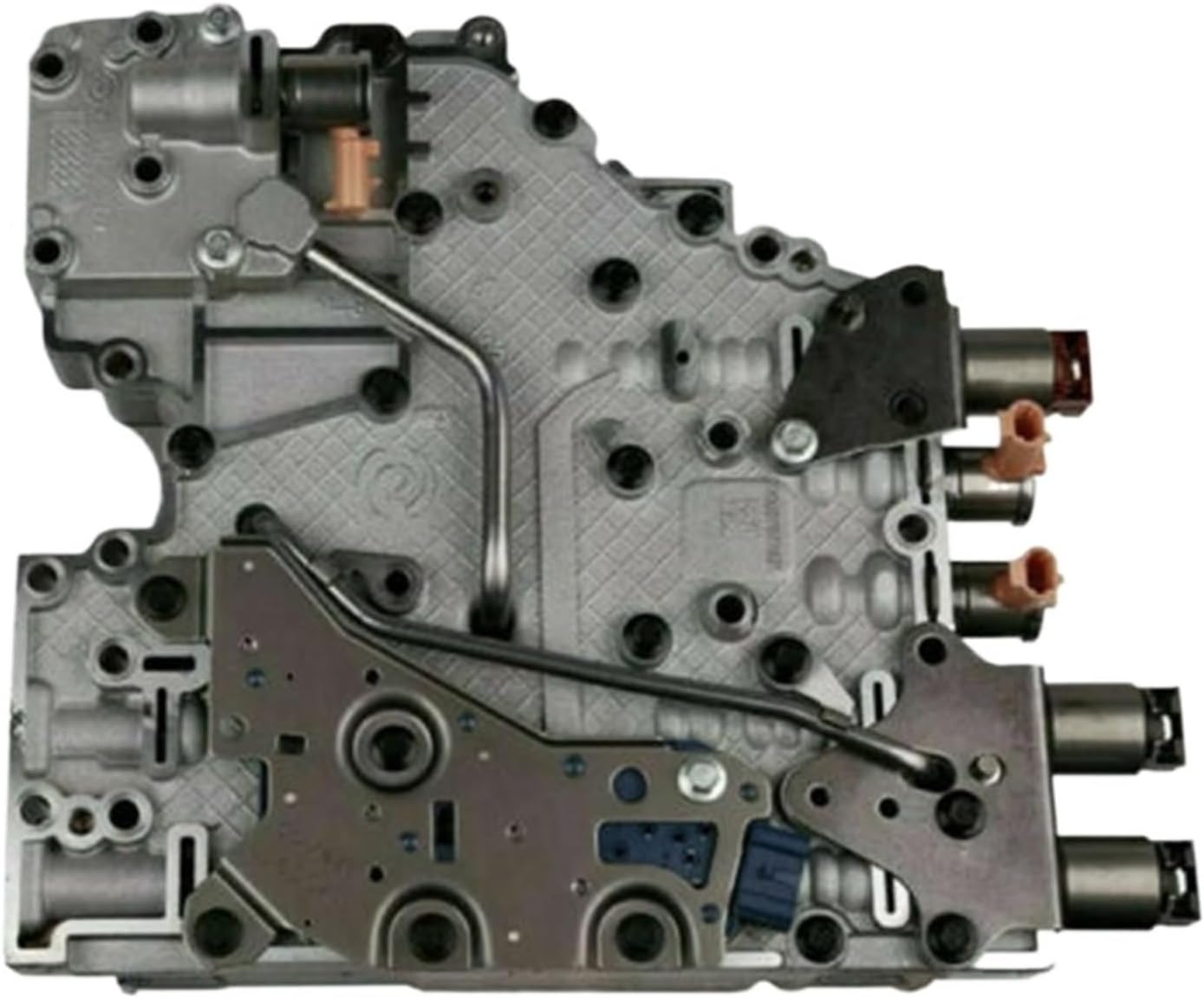
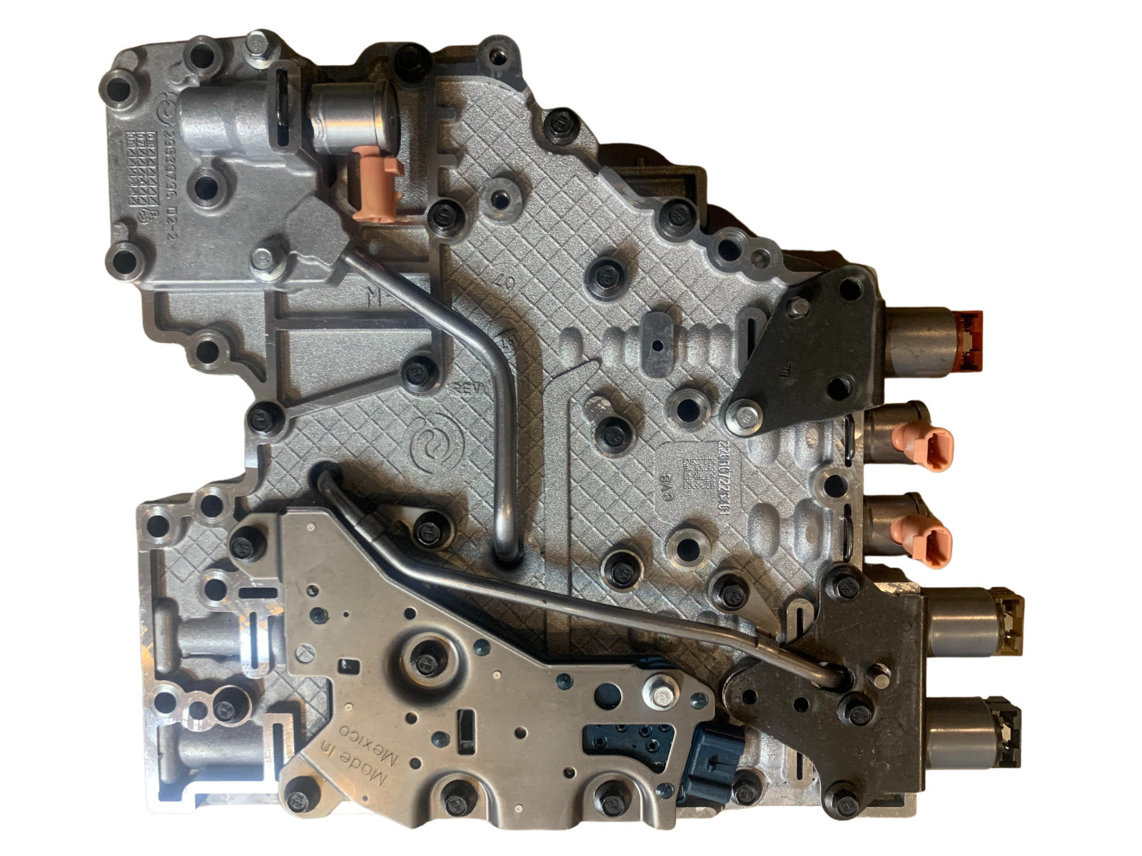
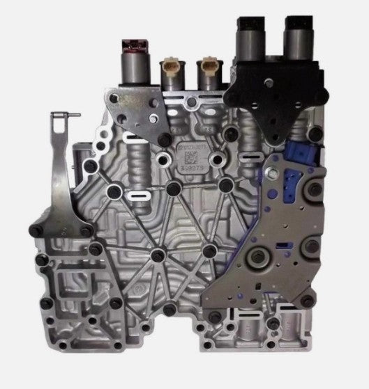
The 1000/2000/2400 valve body went through four versions that do not interchange freely. Sonnax's breakdown:
| Years | Speeds | Quick ID | Castings / plate |
|---|---|---|---|
| 2001–2003 | 5-speed | One tube, six solenoids | Upper 29536838, lower 29536840, plate 7440 |
| 2004–2005 | 5-speed | One tube, seven solenoids | Upper 29539798 (also 29541592), lower 29539802, plate 9793 |
| 2006–2009 | 6-speed | Two tubes, seven solenoids | Upper 29542971, lower 29543340, plate 29542962 (stamped 2962) |
| 2010–later | 6-speed | No tubes, seven solenoids | Upper 29550905, lower 29550908, plate 29545980 (stamped 5980) |
One trap worth knowing: modulated main pressure housing casting 29539796 is shared between the '04–'05 five-speed and the '06–'09 six-speed, differing only in the hole for the second tube. The 2010-later body interchanges with nothing earlier.
The order of operations that works
- Ask which gear it is stuck in. Map it against 1st, 3rd, 5th and Reverse to learn where in the drive cycle it defaulted. A flashing PRNDL or inhibit message instead routes you to inputs, not hydraulics.
- Battery, G102 ground and charging voltage. The solenoid monitors need 9 to 18 volts to run at all.
- Pull codes from every module and record freeze frame before clearing. U0101 or P0880 reframes the entire job.
- Check fluid level and condition, level and at temperature. Low fluid produces erratic pressure switch signals, which produces inhibits.
- Inspect the TCM harness where it passes the accessory drive belt, and look for a non-OEM serpentine belt.
- Graph input speed, output speed, engine speed, TFT and the pressure switch states on a road test. Both speed sensor codes together points at the shared circuit, not two dead sensors.
- If P0872, P0871 or P1711 is present, plan on the valve body, and vacuum-test it once it is out. The module already retried the S3 valve twice; low readings at the E-shift, trim and control main relief bores confirm the wear before you reassemble on hope.
Need parts for this job?
Allison 1000 valve body kits, oversized valve and reamer kits, shift solenoid sets, deep pans, filter and gasket kits, braided cooler line kits and the shaft tooling — shipped from the USA.
Shop Allison 1000 parts →Keeping it out of default
Most Allison 1000 default conditions are wear conditions that finally crossed a threshold, and fluid is the lever you actually control. Allison's current on-highway specification is TES 668, covering the 1000 Series along with the 2000, 3000 and 4000 Series; TES 295 and TES 468 are the older approved specs for the same units, and Allison recommends upgrading to TES 668 at the next service interval. Keep filter changes on schedule and inspect cooler lines on trucks that tow — heat is what turns a marginal valve bore into a stuck valve.
If the unit is coming apart anyway, fix the E-shift valve bore with an oversized valve kit rather than reusing a bore you know is damaged. Sonnax's layout also flags the control main relief valve (37000-19) for loss of shift solenoid control pressure and the manual valve (37000-28K) for low line pressure and delayed Drive or Reverse — cheap on the bench, expensive to skip.
Related reading: our Allison 1000 service guide, Allison 1000 TCC shudder diagnosis, how to check line pressure, and bench testing transmission solenoids.
Sources
- General Motors — "2004 ALLISON 1000 SERIES transmission when used with 8.1L (L18) engine: Transmission Diagnostic Parameters." Backs every monitor threshold in this article: P0872 (S3 valve commanded stroked to destroked, E pressure switch fails to indicate destroked for more than 2 seconds at 0°C, up to 4 seconds at −40°C, 25 ms rate, Type A); the P0870/P0873 pending threshold of 0.0195 seconds, the two S3 valve retry attempts and the three malfunction cases; the 5-second and 30-second extensions on suspected main pressure dropout; P0716 Case 1 at 800 RPM per sample for 0.15 seconds and Case 2 over 80 samples with counters at 5; P0717 below 61 RPM input with output above 500 RPM for 1 second; P0722 enable conditions including "no hydraulic default condition"; the P0731–P0736 ratio logic (2-second timer, output speed 100 RPM, gear slip above 100 RPM, commanded diagnostic response range, 200 RPM converter slip over 10 samples); P0746 and P0776 at 60 RPM output and 75 RPM commanded gear slip (150 RPM rough road); and the P0748/P0778 target current formula with its 8-ohm, 0.00394 per °C temperature correction and the 9 to 18 volt enable window. gsi.ext.gm.com
- General Motors Service Bulletin PI1522 (August 2015), via NHTSA. Backs the hydraulic default range map — "The hydraulic default ranges on the A1000 are 1st, 3rd, 5th & reverse," with 1st to 1st, 2nd and 3rd to 3rd, 4th/5th/6th to 5th, and Reverse to Reverse — plus the 2015–2016 Silverado and Sierra (RPO MW7) TCM harness interference with the engine accessory drive belt, the tie-strap repair to the battery negative cable, and the associated DTC keyword list. static.nhtsa.gov
- General Motors Service Bulletin PI0310C (November 2013), via NHTSA. Backs the 2007–2011 Silverado and Sierra A1000 (RPO MW7) range-inhibit condition with P0880 and/or U0101, the G102 engine-block ground resistance cause, the electrostatic charge generated by certain aftermarket serpentine belt compounds, the instruction not to replace the TCM before resolving root cause, and the TCM relocation procedure to the top of the UBEC cover using adhesive or hook-and-loop rather than push pins. static.nhtsa.gov
- Sonnax — "Identifying Allison 1000/2000/2400 Valve Bodies" (February 8, 2017). Backs the four valve body versions and their casting and separator plate numbers, the six-versus-seven solenoid and one-versus-two tube quick ID, the shared 29539796 modulated main pressure housing between '04–'05 and '06–'09, the 2010-later redesign (new SV1/SV2/SV3 and control main valve, solenoid G replaced by a PWM main modulator solenoid), and the sticking E-shift valve / shift valve 3 as the most common valve body problem — including the inboard bore damage, the pressure switch failing to change state, the resulting P0872, and the transmission going into failsafe. sonnax.com
- Sonnax — "GM Allison 1000/2000/2400 Valve Body Layout" (July 8, 2019). Backs the oversized E-shift valve kit 37000-15K ('00–'09) and its listed symptoms of code P0872, code P1711, pressure switch stuck on, failsafe mode and third gear starts, plus the control main relief valve 37000-19 (shift concerns, loss of shift solenoid control pressure) and the oversized manual valve kit 37000-28K (low line pressure, delayed Drive, delayed Reverse). sonnax.com
- Gears Magazine (ATRA) — "Allison Inhibiting Gear Ranges or Shifts." Backs the transmission abuse protection strategy and its inhibit triggers: high engine RPM or throttle/torque above roughly 25 percent at engagement, erratic input/turbine speed, output speed above roughly 300 RPM at engagement, erratic NSBU and PNP switch signals, erratic pressure switch manifold signals from low fluid, valve body, manifold or wiring faults, fluid below −49°F (−45°C), transfer case in neutral, measured slip in a range, and the flashing PRNDL or "Gear Inhibited"/"Shift Inhibited" display. gearsmagazine.com
- Allison Transmission — "Allison Approved Fluids." Backs the fluid specifications: TES 668 as the current on-highway approved specification covering the 1000 Series, 2000 Series, 3000 Series, 4000 Series and H 40/50 EP, with TES 295 and TES 468 as the older approved specifications for the same products and Allison's recommendation to upgrade to TES 668 at the next service interval. allisontransmission.com