P0716 reads "Input/Turbine Speed Sensor A Circuit Range/Performance," and that word performance is the whole story. This is not a dead circuit. The PCM has a turbine speed number in front of it and does not believe it: somewhere in the drive cycle the reported input speed stopped making sense against the other two things the PCM can measure, engine RPM and output shaft speed.
That changes where you look. P0717 (no signal) and P0715 (circuit) send you to wiring and connectors. P0716 sends you to the mechanical side: what the sensor is reading, how far away it is, and whether the transmission is actually doing what the sensor says. Ford also runs a manufacturer-specific companion, P1901, for an intermittent turbine shaft speed sensor circuit. P0716 and P1901 together mean the signal is present but dropping out under load.
First: Confirm the Unit Should Have a TSS at All
The turbine shaft speed sensor is not original equipment on this transmission. It arrived at the start of 2004 production on the E-model builds, mounted in the center of the case, with two supporting changes: a sun shell the sensor can read through, and a center support machined to clear the sensor body. Per the ATRA technical manual section on this family, the 4R70E/75E center support has an extra notch cut out specifically to make room for the turbine speed sensor — install a pre-2004 4R70W support in a TSS case and the sensor will not seat all the way in.
A support that holds the sensor out even a little is a textbook P0716 generator. The circuit is intact, the sensor works, the air gap is now wrong, and the signal falls apart the moment the drum speeds up. ATRA notes that grinding the notch into the support yourself will not cause a problem. Bolting it up as-is and hoping will.
How the Sensor Reads Speed Here (and Why That Is Unusual)
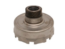
On most transmissions the input speed sensor stares at a dedicated tone ring. Not here. On a 2004-up 4R70E/4R75E the turbine shaft speed sensor reads raised stampings on the forward clutch drum, and it reads them through the sun shell. The shell sits between the sensor and its target, and that only works because the shell is non-ferrous. It is a deliberate material choice, and it is invisible from three feet away. Sonnax builds its Smart-Tech forward clutch drum 76654-01K to be compatible with both ISS-equipped and non-ISS-equipped applications for exactly this reason — on this unit the forward drum is a reluctor as well as a clutch drum, and Sonnax lists ratio codes among the symptoms that drum cures.
Cause 1: A Repaired Sun Shell (The Signature P0716 Failure)
ATRA documented this one directly in Technical Bulletin #1929 (October 2019), and the description is exactly what a customer will describe to you: after a rebuild, the turbine shaft speed sensor reads correctly sitting still in Park, Neutral, Drive and Reverse — then the vehicle moves, and the signal goes crazy.
Good at rest, garbage under way, is the definition of range/performance. And the cause is usually not the sensor. Somebody welded up the wear area on the sun shell. TSS-equipped applications require a non-ferrous shell so the sensor can read the forward clutch drum through it, and the ferrous material in the welding rod creates interference in the signal. ATRA's instruction is blunt: do not use a repaired sun shell in a unit that has the turbine shaft speed sensor.
The test costs nothing. Put a magnet on the shell before it goes in. It should not stick anywhere. If it sticks at the repaired wear area, you have found your code. And if you are replacing the shell, replace the set — the 2004-up shell, bearing and forward sun gear stack together, and swapping only the shell leaves your end play wrong before you start measuring.
Cause 2: Air Gap
Air gap kills a speed signal without breaking a wire, and Ford's own family history shows how easy it is to get wrong. On the AX4S and AX4N, Sonnax documented that mixing a sensor from one unit with a driven sprocket from the other has two outcomes: the too-long sensor contacts the reluctor and gets destroyed, and the too-short combination leaves an air gap that is too great, which can cause ratio codes and/or a turbine speed sensor code. On that unit the correct gap is approximately .120 in.
The principle transfers directly. Excess gap does not kill the signal outright — it weakens the amplitude. At idle in Park the drum is turning fast enough to produce a readable pulse. Load the unit, get the temperature up, and the amplitude drops below what the PCM will accept. You get a code that only sets while driving, which is precisely the P0716 profile. On a 4R70W the gap is set by parts stack-up, so confirm the center support is the right one and the sensor seats fully before you close the case.
Cause 3: A Heat-Aged Sensor or an Induced Signal
These are AC-generator style sensors, and Wayne Colonna covered the failure mode in Transmission Digest: as the sensor weakens from heat or age, the amplitude of the AC signal drops, producing complaints of no upshift to high gear or falling out of gear. Same article, same family of sensors — this style is subject to radio-frequency interference, which causes erratic signals and erratic shift and TCC complaints.
So if the code sets on a hot restart or after a long highway pull and clears when the truck cools off, suspect the sensor even if it ohms fine cold. If it sets when the ignition system is under load — hard acceleration, a worn plug wire, an aftermarket ignition box — look at harness routing before you condemn anything. A speed sensor lead zip-tied against a secondary ignition wire is a code waiting to happen.
Cause 4: The Reluctor Stopped Turning
Rare here, but worth knowing. In GEARS Magazine, Keith Clark documented a Ford 6F55N where the snap ring holding the cast iron reluctor to the 3-5-reverse drum blew off. When the clutch applied, oil pressure pushed the retainer against the end cover and stopped it rotating, and input speed dropped to zero — but only in 3rd and 5th. The sensor was perfect. Its target had quit.
On a 4R70W the analogue is a cracked or broken forward clutch drum, and Sonnax lists broken clutch drum, slipping gears and ratio codes together as the symptoms its Smart-Tech drum addresses. If input speed collapses in specific gears and is clean in others, stop testing the sensor and start thinking about what it is pointed at.
Cause 5: The Sensor Is Right and the Transmission Is Slipping
The possibility most people skip. Range/performance means the input speed does not agree with the rest of the data — and if the transmission is genuinely slipping, the sensor is reporting the truth and the truth is out of range.
Converter clutch slip is the common version on this family. Ford's AODE/4R70W torque converter uses three oil circuits rather than the usual two: converter impeller (CI), converter turbine (CT), and a third Converter Bypass (CBY) circuit that controls apply and release of the converter clutch. Sonnax's Gregg Nader laid out how bypass oil is fed between the front cover and the lock-up piston to hold the clutch released, and how the PCM reverses that flow to apply it.
When the bypass clutch control valve bore wears, that circuit leaks and the clutch never fully clamps. Sonnax's valve body layout for the AODE, 4R70W, 4R75W, 4R70E and 4R75E lists the symptoms for its oversized bypass clutch control valve 76948-31 as code 628, 741, 1741, 1744, no lockup, TCC slip and low cooler flow. Those TCC codes are calculated from the same turbine speed signal P0716 is complaining about. So vacuum test the valve body bores before you order a sensor: if the bypass clutch control bore will not hold vacuum, you have a hydraulic problem wearing a sensor code as a disguise.
Diagnosing It on the Scan Tool
Do this before you pull the pan. Graph three PIDs together rather than reading them one at a time: turbine or input shaft speed (RPM), output shaft speed (RPM), and engine RPM. Add commanded gear and TCC duty cycle if your tool has them.
- Stationary check. In Park and Neutral at idle, turbine speed should report real RPM close to engine speed, since the converter turbine is being driven. A flat zero here with the engine running points at circuit or air gap, not range/performance.
- Ratio math. As GEARS put it in its scan data walkthrough: divide turbine speed sensor RPM by output speed sensor RPM and the result is the current gear ratio. Compare that against the unit's published ratios — on a 4R70W, roughly 2.84 in 1st, 1.55 in 2nd, 1.00 in 3rd and 0.70 in overdrive. On spec means the sensor is telling the truth; wandering means the signal is the problem.
- Trust the raw numbers, not the ratio PID. The same article showed a factory tool displaying 4.0:1 while the raw RPMs calculated to 4.55:1 against a 4.54:1 published spec. Do the division yourself.
- Converter slip. Engine RPM minus turbine RPM is converter slip. With TCC commanded on at steady cruise it should fall to a small, stable number. Triple digits there is real slip, and that points at the bypass clutch control valve, not the sensor.
- Hoist test. Run it on the lift with the wheels off the ground and watch the same PIDs. Unloaded, the transmission should not slip, so that separates a bad signal from real clutch slip.
Do Not Confuse This With an Output-Side Code
Ratio faults can be set from either end, so if P0716 shows up next to P0720-P0722 or a speedometer complaint, deal with the output side first. Transmission Digest documented the change: at the start of 2004 production this family got extended parking lugs on the rear ring gear to trigger the output speed sensor, replacing the earlier holes-in-the-ring-gear design, and that required a PCM strategy change too. The parts do not interchange. The 2004-up ring uses the OSS sensor with the white body and black connector; 2003-and-earlier units used the all-black sensor, which is 0.083 in. longer. Put a 2003 ring gear behind a 2004-up PCM and vehicle speed is wrong, every ratio calculation is off, and you get codes on both sensors. That is a parts-matching mistake, not a sensor failure.
Fluid, Level, and What Not to Add
Check level and condition before any of this. A low or aerated fluid level causes real slip, and real slip sets range/performance codes honestly. The 4R70W, 4R70E, 4R75W and 4R75E all specify MERCON V per Ford's fluid application chart, and that same chart carries an explicit manufacturer caution against supplemental transmission fluid additives, treatments and cleaning agents. Do not pour a bottle of stop-slip into a unit you are trying to diagnose — you will change the numbers you are reading.
Capacity depends on the application and whether the converter drains. A pan drop and filter on a typical F-150 or Explorer takes about 5 quarts; a full dry fill including a drained converter and cooler lines runs closer to 13 to 14 quarts. Set the final level hot, in gear, on level ground, against the vehicle's own service data.
The Short Version: A P0716 Checklist
- Confirm the unit is a 2004-up TSS build and the PCM expects one.
- Check fluid level and condition cold and hot. Fix that first if it is off.
- Graph turbine, output and engine RPM. Note where in the drive cycle the turbine trace breaks up.
- Divide input by output and compare to 2.84 / 1.55 / 1.00 / 0.70.
- Watch engine RPM minus turbine RPM with TCC commanded on. Large, unstable slip points at the bypass clutch control valve.
- Reads right in Park and falls apart moving? Magnet-test the sun shell.
- Confirm the center support has the sensor notch and the sensor seats fully.
- Vacuum test the valve body bores before replacing hydraulic parts by guess.
- Inspect the forward drum stampings for cracks while it is apart.
- Replace the sensor last, and route the lead away from ignition wiring.
FAQ
What is the difference between P0715, P0716 and P0717 on a 4R70W?
P0715 is a general turbine speed sensor circuit fault and P0717 means no signal at all, so both push you toward wiring, connectors and a dead sensor. P0716 means the signal exists but does not agree with engine speed and output speed. On this transmission that points at what the sensor is reading through — the sun shell — or at air gap, rather than at the circuit.
Why does my 4R70W read turbine speed fine in Park but go erratic once I drive it?
That exact pattern is documented in ATRA Technical Bulletin #1929. It is normally a sun shell that has been welded or otherwise repaired in the wear area. The turbine shaft speed sensor has to read the forward clutch drum through the shell, so the shell must be non-ferrous, and welding rod material in a repair creates interference in the signal. Test the shell with a magnet before blaming the sensor.
Can a bad torque converter clutch cause P0716?
Yes, indirectly, and it is a common miss. The PCM calculates converter slip from turbine speed, so a clutch that will not fully apply produces implausible numbers from a perfectly good sensor. On this family a worn bypass clutch control valve bore is the usual cause, and Sonnax lists TCC slip, no lockup and codes 741, 1741 and 1744 among the symptoms its oversized valve addresses.
Will replacing the turbine speed sensor fix P0716?
Sometimes, but it is the wrong first move. A heat-aged sensor does lose signal amplitude and will set this code, so a sensor that fails on a hot restart is a legitimate suspect. Rule out the sun shell, the center support notch, air gap and real converter slip first, or you will buy the sensor twice.
Does P0716 put a 4R70W in limp mode?
It can. Without a trustworthy turbine speed number the PCM loses its slip calculation and defaults to failsafe: harsh engagement, a fixed gear and no converter clutch. Driving miles that way puts full line pressure through the clutches on every shift, which is how a sensor complaint turns into a clutch job.
Working a 4R70W this week?
Sun shells, speed sensors, forward drums, solenoid kits, valve body parts and rebuild kits — shipped fast from the USA.
Shop 4R70W parts →Sources
- ATRA — Technical Bulletin #1929, "4R70W, 4R75W, 4R70E, 4R75E: ISS Codes, Erratic Reading," October 2019 (PDF). Backs the signature failure in this article: after a rebuild the turbine shaft speed sensor reads correctly in Park, Neutral, Drive and Reverse and then goes erratic once the vehicle moves; TSS applications require a non-ferrous sun shell so the sensor can read the forward clutch drum through it; ferrous welding-rod material in a repaired wear area creates signal interference; check the shell with a magnet, and do not use a repaired shell in a TSS unit. atracom.blob.core.windows.net
- ATRA — "Ford 4R70W/4R70/75E" technical manual section, 2009 (PDF). Backs the 4R70E/75E center support having an extra notch cut out to clear the turbine speed sensor, the fact that a 4R70W support will not let the sensor install fully into the case, and that grinding the notch is an acceptable field fix. atracom.blob.core.windows.net
- Sonnax — "AX4S and AX4N Turbine Speed Sensors," Mike Steen, March 19, 2004. Backs the air gap section: the wrong sensor and reluctor combination either contacts and damages the sensor or leaves an air gap that is too great, which can cause ratio codes and/or a turbine speed sensor code, on a unit where the correct gap is approximately .120 in. sonnax.com
- Sonnax — "Ford AODE, 4R70W, 4R75W, 4R70E, 4R75E Valve Body Layout," July 20, 2021. Backs the converter-clutch slip section: the oversized bypass clutch control valve 76948-31 is listed against code 628, 741, 1741, 1744, no lockup, TCC slip and low cooler flow, tying a worn bypass clutch control bore to the slip numbers calculated from turbine speed. sonnax.com
- Sonnax — "Ford Bypass Converter Clutch Circuits," Gregg Nader, September 21, 2003. Backs the three-circuit description of the AODE/4R70W torque converter: converter impeller (CI), converter turbine (CT) and the third Converter Bypass (CBY) circuit that controls apply and release of the converter clutch by feeding oil between the front cover and the lock-up piston. sonnax.com
- Transmission Digest — "Getting Up to Speed," Wayne Colonna, June 1, 2005. Backs the sensor-aging and interference section: AC-generator style speed sensors lose signal amplitude as they weaken from heat or age, causing no upshift to high gear or falling out of gear, and this sensor style is subject to radio-frequency interference producing erratic signals with erratic shift and TCC complaints. Also backs the 2004 output-side change to extended parking lugs on the rear ring gear, the 0.083 in. sensor length difference and the white-body versus all-black sensor identification. transmissiondigest.com
- GEARS Magazine (ATRA) — "Transmission Scan Data Analysis," Jerry Stewart, May 1, 2026. Backs the scan tool method: divide turbine speed sensor RPM by output speed sensor RPM to get the current gear ratio and compare it to the published spec, graph both sensors together, run the vehicle on a hoist with the wheels off the ground to separate a sensor fault from clutch slip, and do not trust a factory ratio PID over the raw RPMs — in the example the tool showed 4.0:1 while the raw numbers calculated 4.55:1 against a 4.54:1 spec. gearsmagazine.com
- GEARS Magazine (ATRA) — "The Disappearing Input Speed Sensor Signal," Keith Clark, March 30, 2018. Backs the stopped-reluctor failure mode: on a Ford 6F55N the snap ring retaining the cast iron reluctor to the 3-5-reverse drum failed, clutch apply pressure pushed the retainer against the end cover and stopped it rotating, and the input speed signal dropped to zero in 3rd and 5th gear with a healthy sensor. gearsmagazine.com
- Ford Customer Service Division — "Automatic Transmission Fluid Chart" (PDF). Backs MERCON V as the specified fluid for the 4R70W, 4R70E, 4R75W and 4R75E, and the manufacturer caution against supplemental transmission fluid additives, treatments and cleaning agents. fcsdchemicalsandlubricants.com