P0715 is "Input/Turbine Shaft Speed Sensor A Circuit," and on a 5R55W it usually walks in the door as a truck that shifts like a dump truck, will not lock the converter, and has a wrench light on. The PCM has stopped believing the turbine speed number, so it stops doing everything that number feeds: adaptive shift control, converter clutch slip control and ratio monitoring all go away at once. What is left is failsafe.
The thing that makes this code cheap to diagnose on this particular transmission is a detail most people do not know until somebody tells them. Ford used the same sensor part in both speed sensor locations. The turbine shaft speed sensor and the output shaft speed sensor on a 5R55N, 5R55W or 5R55S are the same piece, Ford part number XW4Z-7H103-AA, both bolted into the driver side of the case — the TSS forward, the OSS back toward the tail. You already own the test part. It is on the other side of the same transmission.
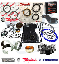
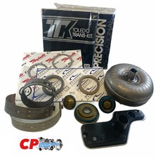
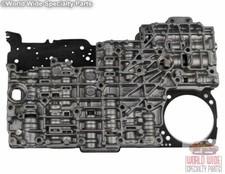
Know Which Unit You Have Before You Order Anything
The 5R55 family is four transmissions wearing similar cases, and mixing their parts is how a one-code job turns into a rebuild. Per Sonnax, the N ran '99-'02 in the Jaguar S-Type, Lincoln LS and Thunderbird; the W showed up in Explorers and Mountaineers for '02-'03 before the S took over in '04-'05. The W and S are separated internally by the overdrive sun gear — 24 teeth on the W, 38 on the S.
Sonnax gives a quick external tell if you are staring at a swap-meet unit with no tag: the N has two cast bosses just behind the intermediate servo cover, while the W and S have only one, for the PCC pressure port. With the pan off, the N also carries a reverse pressure switch that the W and S solenoid has no terminals for.
How the Signal Actually Gets to the PCM
These are two-wire magnetic pickups. There is no reference voltage to test for and no separate ground to lose — the sensor generates its own AC signal as the reluctor teeth pass the pole piece, and the PCM squares that up into an RPM value. Two consequences follow, and both matter here:
- Amplitude scales with speed. A marginal sensor or an excessive air gap can still make a readable pulse at high drum speed and fall apart at low speed, or the reverse if it is a wiring fault that only opens under vibration. That is why so many of these are intermittent and why the code sets in one part of the drive cycle and not another.
- The wiring leaves the case. That is a gift. GEARS points out that the lab scope method only works when the speed sensor wiring travels outside the transmission case. On a 5R55W it does, so you can put a scope on the raw AC waveform and confirm it reaches its upper and lower voltage levels without dropping the pan.
Do not forget the third sensor
The swap test below covers the TSS and OSS, but Ford's 5R55W/S service information lists a third magnetic pickup: an intermediate shaft speed (ISS) sensor mounted externally at the center of the case, reporting planetary sun gear speed for pressure control. In Ford's 2002 Explorer DTC chart it has no DTC of its own, so Ford tests it inside the turbine-code pinpoint test ("Test E: ISS, OSS & TSS sensors"). That test calls for each circuit to read under 5 ohms end to end and over 10 kilohms to ground, with the sensor measuring 325-485 ohms at 70°F. Transmission Digest published a 2003 Lincoln LS 5R55S case where P0715, P0717 and P0718 came back after a new turbine sensor. The scope at the PCM showed a flat-line ISS signal, and the scan tool had no ISS PID to show it. Later Ford calibrations did give it codes: Ford's 2005 Mustang 5R55S chart lists P0791 (ISS signal loss) and P0794 (intermittent ISS), both sent to the same Test E, so on a later-year truck check for those codes before assuming the ISS cannot set one.
Cause 1: The Connector, Not the Sensor
Start here, because Ford already told us it is a problem. ATRA's 2005 Ford manual documents that 2002 Explorer and Mountaineer vehicles equipped with the 5R55W can get water intrusion in the transmission solenoid body connector, setting transmission codes and lighting the TCIL. The released repair is not a sensor and not a solenoid body — it is transmission wiring harness part number 1L2Z-7C078-AB, a new harness released specifically to prevent the condition.
Pull the case connector and look inside with a light before you do anything else. Green corrosion, a white crust, or terminals that have lost their spring tension are your answer. Added resistance in series with a signal that is only a couple of volts to begin with looks exactly like a failing sensor from the PCM's side of the harness, and no amount of new sensors will fix it.
While you are in there, check that the harness is not draped over the pan rail studs or laid against the exhaust. Chafe-through on a two-wire circuit is a five-minute find.
Cause 2: The Sensor, and the Swap Test That Proves It
Because the TSS and OSS are the same part, you can settle sensor-versus-everything-else in ten minutes with nothing on the shelf. Unplug both, swap them physically between the two case bores, clear codes and drive it.
- The fault moves to the output side — you now have a speedometer complaint or an output speed code — the sensor is bad. Buy one.
- P0715 stays put — the sensor is fine. Your problem is the circuit, the bore, or what the sensor is pointed at.
GEARS makes the same point from the other direction when it tells you to watch input speed in Park and Neutral with the engine running: it should read roughly engine speed, because the converter turbine is being driven. A flat zero there with a good circuit means a bad or swapped sensor. Two identical sensors in two identical bores get put back in the wrong holes during rebuilds more often than anybody admits, and a unit that reads output speed on the input PID will never make sense to the PCM.
Cause 3: What the Sensor Is Pointed At Stopped Turning
This is the one that costs people two sensors and a week. Keith Clark documented it in GEARS on a Ford 6F55N: input speed fell to zero in 3rd and 5th only, a P0717 set, two brand new factory sensors behaved identically, and a pinpoint test of the circuit came back good even while wiggling the harness and connectors. The unit came out. The snap ring holding the cast iron retainer — which is the reluctor wheel for the input speed sensor — had blown off the 3-5-reverse drum. With the ring gone and the locator tab broken, clutch apply pressure pushed the retainer against the end cover and stopped it rotating. The sensor was perfect. Its target had quit.
The lesson transfers to any unit, this one included: if the signal disappears in specific gears and is clean in the others, stop testing the sensor. A sensor fault does not know what gear you are in. Something that only fails when a particular clutch or band applies is mechanical or hydraulic, every time.
Cause 4: The Fluid and the Solenoid Body
The 5R55W takes MERCON V, and on this unit that is not a throwaway line. Sonnax documented that the factory ATF fill in the 5R55E, W, S and N prior to May 2005 was an early MERCON V that degraded and took solenoids with it. Ford released an interim additive package, 4L2Z-19B546-AB, under bulletin FSA 04B22, and the final resolution was the revised MERCON V sold as XT-5-QM in the black quart container. Sonnax's warning is the part that gets ignored: if you service one of these and leave any trace of the questionable fluid behind, you shorten the service life of the next solenoid too.
Why a fluid problem shows up wearing a speed sensor code: this unit runs four on/off shift solenoids, one PWM solenoid for TCC control and three variable force solenoids, per Transmission Digest. Per ATRA, PCA and PCB raise and lower mainline pressure through every range from Park to Manual 1, while PCC controls reverse engagement pressure and direct clutch application in overdrive 4th, 5th and manual 4th. Contaminate those and pressure control goes erratic, the unit slips, and the ratio the PCM calculates from turbine speed stops matching the gear it commanded.
If the pack has to come out, use the right one. ATRA lists 2002-03 Ford 5R55W/S and 2003 Lincoln 5R55S taking pack 1L2Z-7G391-AG, with 2004-on units taking 4L2Z-7G391-AA, superseded by the updated 9L2Z-7G391-A that Ford recommends for those later builds. Fitting the wrong-generation pack delivers slightly different pressures, and ATRA notes the classic result is a flare on the 2-3 shift after an otherwise clean rebuild.
One more Sonnax detail worth ten seconds of your time: the VFS solenoids are tested and shipped wet, but that lubricant drains off in handling. Fill the circuits with new MERCON V and pull fluid through the solenoid with vacuum before you bolt it up, or the first road test will lie to you. And Ford units built after 2002 use adaptive strategy, so run a relearn after any solenoid service.
Cause 5: The Sensor Is Telling the Truth
Sometimes the number really is implausible because the transmission really is slipping. On the 5R55W the usual hydraulic culprit is bore wear, and Sonnax is specific about the order it happens in: the TCC modulator bore and the main regulator bore wear first because they cycle the most, and as cycle rate climbs — higher in city traffic — the VFS1, VFS2 and VFS3 modulator bores follow, reducing clutch and servo pressure. Adaptive strategy compensates and hides it for a while. Then you get gear ratio codes or outright slippage. As Sonnax puts it, the solenoid or the servo pin bore usually takes the blame when the actual problem is that the VFS modulator valves cannot supply enough pressure.
Vacuum test before you buy hydraulic parts. Sonnax's 5R55W/S guide lists the oversized VFS modulator control valve kit 56947J-19K against flare shifts, low line pressure and pressure control out-of-range codes, and the boost valve kit 56947J-74K against no Reverse, low Reverse boost, delayed engagement, soft shifts and low line rise. Sonnax also describes a wet air test you can run on the bench or in the vehicle: remove the solenoid base plate, reattach it over the separator plate, and inject ATF with 40-60 psi of air into the circuits. Excess leakage past a valve aerates the fluid in service, which then reads as an inflated fluid level and produces erratic pressure — which produces erratic data.
And do not mix plates. ATRA warns that not every 5R55W/S uses a third check ball — two holes in the plate over the bath tub area means it needs one, a single hole means it does not — and a mismatched separator plate can cause serious failure. Transmission Digest adds that Ford reduced the separator plate hole sizes in the VFS1 and VFS2 oil circuits with the 2009 casting change, so a late plate on an early body changes the pressure those solenoids actually deliver.
The Scan Tool Sequence
Do this before the truck goes on the lift.
- Read the enabling criteria for the code, then the freeze frame. GEARS is right that this is the step everyone skips. Note the speed, temperature and gear where it set. A P0715 that only sets hot is a different problem than one that sets at every cold start.
- Diagnose the code with the most authority first. If P0715 is stored alongside a pressure control solenoid code, chase the pressure code — a faulty line pressure solenoid can generate a gear ratio error on its own.
- Key on, engine running, in Park. Turbine speed should report close to engine RPM. A zero here is a circuit, a connector, or a swapped sensor, not a range problem.
- Graph turbine RPM, output RPM and engine RPM together on the road test. Reading them one at a time tells you nothing; the relationship between them is the whole diagnosis.
- Do the ratio math yourself. Turbine RPM divided by output RPM is the ratio you are actually in. Compare it to the published spec for the gear commanded, and ignore the scan tool's own ratio PID — GEARS documented a factory tool displaying 4.0:1 while the raw numbers worked out to 4.55:1 against a 4.54:1 spec.
- Sort sensor from slip by pattern. Slipping clutches set ratio faults only in the gears those clutches hold. Bad sensors and wiring set unrelated ratio codes at random, with nothing in common.
- Run it on the hoist, wheels off the ground. Unloaded, the clutches should not slip. Codes that still set there are electrical.
- Scope the sensor at the case connector. The wiring leaves the case on this unit, so confirm the AC waveform reaches its upper and lower voltage levels at speed instead of guessing from an RPM PID that has already been filtered.
What Not To Do
Do not pour anything in it. Ford's own fluid application chart carries an explicit caution against supplemental transmission fluid additives, treatments and cleaning agents, and on a unit you are trying to read live data from, a friction modifier changes the numbers you are reading.
Do not clear the code and hand the keys back with the light off. In failsafe this transmission engages and shifts at full line pressure. Every mile driven that way is punishing the direct clutch and the bands, and the customer comes back with a bigger bill than the one they refused.
Do not replace the solenoid pack first because it is the part everybody stocks. On a 2004-on unit that is the wrong-generation-part trap waiting to happen, and it does nothing whatsoever if the fault is a corroded case connector.
The Short Version: A 5R55W P0715 Checklist
- Read the freeze frame and the enabling criteria. Note temperature, speed and gear.
- If a pressure control solenoid code is also stored, chase that one first.
- Open the transmission solenoid body case connector and inspect for water intrusion and corrosion.
- Check turbine speed in Park with the engine running. It should read near engine RPM.
- Swap the TSS and OSS sensors. If the fault follows the sensor, the sensor is bad.
- Scope the AC waveform at the case connector at speed.
- Graph turbine, output and engine RPM on a road test and divide input by output for the live ratio.
- Signal dies only in specific gears? Think reluctor and clutch apply, not sensor.
- Check fluid level and condition. Confirm MERCON V, and that the early degraded fill is gone.
- Vacuum test the VFS1, VFS2, TCC modulator and main regulator bores before buying hydraulic parts.
- If the pack has to come out, match it to the year: 1L2Z-7G391-AG early, 9L2Z-7G391-A for 2004-on.
- Prime the VFS solenoids with new fluid and vacuum before installation, then run an adaptive relearn.
FAQ
Are the input and output speed sensors the same part on a 5R55W?
Yes. Ford uses one sensor, part number XW4Z-7H103-AA, in both the turbine shaft speed and output shaft speed locations on the 5R55N, 5R55W and 5R55S. Both live on the driver side of the case, the TSS forward and the OSS toward the tail. That interchangeability gives you a free test: swap the two sensors and see whether the fault moves with the sensor or stays at the location.
Can a bad turbine speed sensor put a 5R55W in limp mode?
It can. Without a believable input speed number the PCM loses its converter slip and ratio calculations and falls back to failsafe, which on this unit means harsh engagement, a fixed gear and no converter clutch. Driving it that way sends full line pressure through the clutches and bands on every engagement, which is how a sensor complaint turns into a rebuild.
Will P0715 come back after I replace the sensor?
It will if the sensor was not the fault. On 2002 Explorer and Mountaineer 5R55W units ATRA documented water intrusion in the transmission solenoid body connector setting transmission codes, fixed with wiring harness 1L2Z-7C078-AB rather than a sensor. Check the connector and the circuit before you buy parts.
What fluid does a 5R55W take, and does fluid matter for this code?
MERCON V, per Ford's own fluid application chart. It matters indirectly. Sonnax documented that the factory fill in these units prior to May 2005 was an early MERCON V that degraded and damaged solenoids, with Ford releasing an interim additive under bulletin FSA 04B22 before settling on the revised MERCON V sold as XT-5-QM in the black quart bottle. Degraded fluid and a struggling solenoid body produce the erratic behavior that gets blamed on a speed sensor.
How do I tell a speed sensor fault from a slipping transmission?
Graph turbine speed and output speed together and divide input RPM by output RPM to get the live ratio, then compare it to the published spec for the gear you are in. GEARS makes the distinction plainly: a slipping clutch sets ratio faults only in the gears that clutch holds, while a bad sensor or its wiring sets ratio faults at random with nothing in common. Running the vehicle on a hoist with the wheels unloaded separates them further.
Working a 5R55W this week?
Solenoid packs, valve body kits, filters, bands, planetaries and full rebuild kits — shipped fast from the USA.
Shop 5R55 parts →Sources
- Sonnax — "Figuring Out the 5R55 Alphabet," Bob Warnke, September 19, 2007. Backs the unit identification and the fluid history in this article: the 5R55W ran in Explorers and Mountaineers for '02-'03 before the S took over in '04-'05, the W uses a 24-tooth overdrive sun gear against the S at 38 teeth, and the factory ATF fill prior to May 2005 was an early MERCON V that degraded solenoids, addressed by Ford's interim additive 4L2Z-19B546-AB under bulletin FSA 04B22 and finally by the revised MERCON V sold as XT-5-QM. Also backs the wet air test at 40-60 psi and the valve body bore wear order. sonnax.com
- ATRA — 2005 Ford technical seminar manual, section "5R55W: TCIL Illuminated, Code P0713, Multiple Codes," page 153 (PDF). Backs the connector root cause: 2002 Explorer and Mountaineer vehicles equipped with the 5R55W and setting transmission codes may have water intrusion in the transmission solenoid body connector, and the released repair is transmission wiring harness part number 1L2Z-7C078-AB. Also backs the separator plate and checkball warning: not every 5R55W/S uses a third check ball, two holes in the plate over the bath tub area means it needs one, and mismatching the plate can cause serious failure. atracom.blob.core.windows.net
- ATRA — 2013 technical manual, "Ford 5R55W/S: Erratic Transmission Operation," pages 112-114 (PDF). Backs the solenoid pack part numbers and solenoid roles: early 2002-03 Ford 5R55W/S and 2003 Lincoln 5R55S take pack 1L2Z-7G391-AG, while 2004-on units take 4L2Z-7G391-AA superseded by the updated 9L2Z-7G391-A that Ford recommends; PCA and PCB are the variable force solenoids that raise and lower mainline pressure from Park to Manual 1, PCC controls reverse engagement and direct clutch application in 4th, 5th and manual 4th, and the remainder are on-off shift solenoids. Also backs the wrong-pack 2-3 flare complaint. atracom.blob.core.windows.net
- Transmission Digest — "Understanding the 5R55S/W Initial Engagements," Jesse Zacarias, November 1, 2012. Backs the solenoid count and engagement behavior: four on/off shift solenoids, one pulse-width-modulated solenoid for TCC control and three variable force solenoids, with only PCA, PCB and PCC involved in forward and reverse engagement, and a complete engagement taking about two seconds. transmissiondigest.com
- Sonnax — "Ford 5R55W/S Vacuum Test Guide," February 21, 2013. Backs the vacuum test targets named here: the VFS1 and VFS2 modulator control valves are listed against flare shifts, low line pressure and pressure control out-of-range codes, the pressure regulator and boost valves against slipping upshifts and delayed engagement, and the TCC modulator valve against P0741 and excess TCC slip. sonnax.com
- Sonnax — "Ford 5R55S, 5R55W Valve Body Layout," December 12, 2014. Backs the specific repair parts and their symptom lists, including the oversized VFS modulator control valve kit 56947J-19K for flare shifts, pressure control out-of-range codes and low line pressure, and the boost valve kit 56947J-74K for no Reverse, low Reverse boost, delayed engagement, soft shifts and low line rise. sonnax.com
- Transmission Digest — "Valve-Body and Plate Changes for the 5R55S," Jeff Parlee, April 1, 2013. Backs the parts-mixing warning: in 2009 Ford changed the 5R55S valve body casting to rough forging RF9L2P 7A101AA and reduced the separator plate hole sizes in the VFS1 and VFS2 oil circuits, with one TSB on that plate, bulletin 09-21-4 dated 11/02/09, for a whistle noise when hot at idle in all gears. transmissiondigest.com
- GEARS Magazine (ATRA) — "Transmission Scan Data Analysis," Jerry Stewart. Backs the scan tool method: look up the enabling criteria and record the freeze frame before testing anything, diagnose the code with the most authority first because a faulty line pressure solenoid can cause a gear ratio error, divide input or turbine speed sensor RPM by output speed sensor RPM to get the current gear ratio and compare it to the published spec, note that slipping clutches set ratio faults only in the gears where that clutch is engaged while faulty sensors and wiring set unrelated ratio codes at random, run the vehicle on a hoist with the wheels off the ground to unload the clutches, scope the sensor where the wiring travels outside the case, and do not trust a factory ratio PID over the raw RPMs, since in the example the tool displayed 4.0:1 while the raw numbers calculated 4.55:1 against a 4.54:1 published spec. gearsmagazine.com
- GEARS Magazine (ATRA) — "The Disappearing Input Speed Sensor Signal," Keith Clark. Backs the dead-reluctor failure mode and the two-sensor lesson: on a Ford 6F55N the snap ring holding the cast iron retainer, which is the reluctor wheel for the input speed sensor, blew off the 3-5-reverse drum; clutch apply pressure then pushed the retainer against the end cover and stopped it turning, and input speed dropped to zero in 3rd and 5th with two brand new factory sensors installed and a circuit that pinpoint-tested good. gearsmagazine.com
- Ford Customer Service Division — "Automatic Transmission Fluid Application Chart" (PDF). Backs MERCON V as the specified fluid for this transmission family and the manufacturer's explicit caution against supplemental transmission fluid additives, treatments and cleaning agents. fcsdchemicalsandlubricants.com
- Ford Motor Company, 5R55W/S Diagnosis service information (2002 Explorer, Mitchell reprint, PDF). Backs the ISS sensor location and function, Test E for the ISS, OSS and TSS, the 5-ohm and 10-kilohm circuit limits, and the 325-485 ohm sensor specification at 70 degrees F. txnj.net (Ford service PDF)
- Randall Peterson — "Why Should I Pay for Diagnosis?" Transmission Digest, September 2012. Backs the 2003 Lincoln LS 5R55S with turbine sensor codes that returned after a new TSS, the missing ISS PID, and the flat-line ISS signal found at the PCM. transmissiondigest.com
- Ford Motor Company, 2005 Mustang Workshop Manual, section 307-01, Diagnostic Trouble Code Charts (PDF). Backs the later-calibration ISS codes P0791 (signal loss) and P0794 (intermittent) and their routing to Pinpoint Test E. themustangsource.com (Ford service PDF)