These two units sat in Ford showrooms at the same time, behind the same 4.6L V-8, and that is where the confusion starts. A 2004 F-150 got a 4R75W. A 2004 Explorer with the same displacement got a 5R55W or 5R55S. Customers hear "Ford four-six automatic" and assume the parts cross over. Salvage yards list them next to each other. They are not related, they do not share a single hard part worth naming, and they fail in completely different places.
Here is the builder-to-builder breakdown: what each one actually is inside, what fails first on each, what the factory numbers are when you put a gauge and a scan tool on one, and the honest answer to which is stronger.
Two Different Families, Not Two Versions of One Thing
The 4R75W is the end of the AOD line. AOD to AODE to 4R70W to 4R75W: longitudinal four-speeds built around a Ravigneaux compound planetary, sharing a case family and a valve body lineage. Sonnax sorts the whole run into two gearset families by ratio, and the 4R70E, 4R70W, 4R75E and 4R75W all live in the 2.84/1.55 family while the AODE sits alone at 2.40/1.46. That one line tells you the 4R75W is a reinforced 4R70W and nothing more exotic than that.
The 5R55W came out of a different program entirely. Per Ford service information for the 2002 Explorer, the 5R55W/S is an electronically controlled five-speed with a four-element torque converter and TCC, three compound planetary gear sets, three bands, three multi-plate clutches and two one-way clutches. Three bands is the headline. Where the 4R75W leans on clutch drums, the 5R55W does a large share of its shifting with band-and-servo hydraulics, and that single design decision drives nearly every failure you will meet on one.
Ford spells out the letters in that same document: the S means synchronous shift and the W means wide ratio. Not a trim code, a description of how the unit shifts.
Where each one lived
Sonnax's Bob Warnke laid the 5R55 family history out cleanly. The 5R55N ran 1999 to 2002 in the Jaguar S-Type 3.0/4.0, Lincoln LS and Thunderbird 3.0/3.9, and was replaced by the S in those cars for 2003. The 5R55W showed up in Explorers and Mountaineers for 2002 and 2003 before giving way to the S in 2004 and 2005 models. The 4R75W meanwhile went to work in F-Series trucks and Mustangs, where Ford wanted the extra capacity of a beefed-up 4R70W behind bigger engines.
Identifying What Is Actually on the Bench
Core tags lie. Learn the physical tells instead.
- Door label TR code. Ford service info puts the transmission letter code on the vehicle certification label on the driver's door post, in the space marked TR next to AXLE. 5R55S is "V" and 5R55W is "R." Fastest check on a vehicle you have not opened yet.
- Count the bosses. Per Sonnax, the 5R55N has two cast bosses just behind the intermediate servo cover, the closer one tapped for PCC. The W and S have only one boss, for the PCC pressure port. You can feel that difference in the vehicle even when you cannot see it.
- Drop the pan. The N carries a base plate similar to a 4R70W over the lower valve body plus a reverse pressure switch. The W and S solenoid has no terminals for that RP switch, and the circuits are different.
- Overdrive sun gear tooth count. This is what separates W from S: the W runs a 24-tooth overdrive sun gear, the S runs 38 teeth. Hard parts vary between them accordingly, so a "5R55" parts order without the letter is a guess.
On the 4R75W side, the era matters more than the badge. Sonnax's Gregg Nader points to a specific 2001 production change: the two-bolt stiffener plate under the 2-3 accumulator was deleted, and the capacity modulator valve and plug were removed with the bore cast closed. If your core has a stiffener plate under that accumulator it is a 2000-or-earlier casting. If the accumulator retainer sits directly on the separator plate, it is 2001-up, and you have a specific problem to solve before it goes back together.
The 4R75W Signature Failure: A Separator Plate That Bows
Most shops find cracked separator plates in 2001-and-newer 4R70W and 4R75W units and assume the 2-3 accumulator retainer beat them up. Nader's finding is that the cracks are a symptom, not the disease.
In these units the forward clutch is fed through the pump at the front and the direct clutch is fed through the output shaft at the rear. Those two circuits stay isolated from each other everywhere except one spot: the casting under the separator plate, below the 2-3 accumulator. With the stiffener plate gone, nothing mechanically clamps the separator plate and gasket in that area. Pressurized oil seeps into the unused valve body passages and pushes up on the plate the same way oil pushes on a servo piston. Nader measured that bow at up to .011 inch under normal forward oil pressure.
Bow the plate and forward clutch pressure cross-leaks straight into the direct clutch circuit. From the driver's seat that reads as soft or inconsistent 2-3 shifts, and it gets written up as a worn clutch pack every day of the week. The tell on teardown: lay the upper gasket over the lower gasket and study the imprint. You will see a heavy valve body imprint across nearly the whole lower gasket except in the 2-3 accumulator area, which is exactly the unclamped region. Put support back into that area on any 2001-up build.
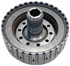
The other 4R75W killer sits downstream. The OE weak point, per Sonnax, is where the direct clutch drum splines strip and the intermediate stub shaft breaks. Once the splines let go, drum and shaft grind each other and the debris takes the planetary with it. The Smart-Tech one-piece drum and shaft kit is the fix, with a shaft rated 50 percent thicker and twice as strong as the best 300M shafts and room for one extra OE-thickness friction, which Sonnax lists as 17 percent more clutch capacity. Match the ratio family: part 76656-01K covers the 2.84/1.55 gearsets (4R70E/W, 4R75E/W) and 76656-02K covers the AODE 2.40/1.46.
The 5R55W Signature Failure: The Servo Pin Bore
This one defines the unit, and it is a direct consequence of the three-band design.
Servo apply oil feeds through the center of the case bridge and into the servo pin, acting on the cover side of the piston. Release pressure comes through the case to the spring side. That pin oscillates constantly in an unhardened aluminum bore. As the bore wears, apply oil leaks into the barrel area of the case, which wrecks shift timing and band apply pressure. As the wear increases, release oil cross-leaks into the apply circuits and exhausts at the shift valves.
Sonnax lists the resulting symptom set on the repair sleeve kit: 1-2, 2-3 and 4-5 flares, gear loss, codes 732, 733 and 735, band lining failure, and loss of overdrive and intermediate servo control. There is one more that people never connect: in reverse, both servos are charged from the release side, so pin bore wear shows up as delayed reverse. If you have a 5R55W with a long reverse engagement and no stored codes, check the pin bores before you condemn the pump.
Foaming is the other consequence. Sonnax notes the 5R55N, W and S are prone to foaming the sump from excess exhaust and valve body wear, which pushes fluid out the vent and gives you a false fill reading. If a 5R55 comes in reading overfull with fluid on the outside of the case, do not just pull out a quart and call it done. You are looking at aerated fluid, and the aeration has a cause.
The repair is a sleeve, not a case. The Sonnax 56361J-01K kit sleeves both the overdrive and intermediate servo pin bores in wear-resistant aluminum, and the S-56361J-TL SERVO-FIX tooling pilots and reams from the pin bore centerline rather than the servo piston bore. That referencing detail is what makes the salvage hold.
Check the cheap thing first
Sonnax's valve body group flags a much cheaper cause of delayed reverse on the same unit: a stuck low/reverse servo control valve. It lives inside the low/reverse servo under a threaded end cap and gets skipped constantly because you cannot see it. If the servo housing went through a hot pressure washer, water, soap and dirt collect in that bore. Pull the valve and spring during cleaning and confirm it strokes freely when clean and dry.
Parts for the two failures above
For the 5R55W, the servo piston kit is the part that goes back in with the sleeve job, and it is where a band-control complaint usually ends. For the 4R75W, the direct clutch drum is the part that saves the planetary. Both ship from CoreTransmissionParts.
5R55W Servo Piston Kit → 4R75W Direct Clutch Drum →Full catalogs: 5R55W parts • 4R75W parts
The Electronics: Four Solenoids Do Not Equal Eight
This is where the two units separate hardest, and it is the reason a 5R55W is a bigger diagnostic job than a 4R75W.
Per Ford, the PCM runs the 5R55W/S through four on/off shift solenoids, one pulse-width-modulated solenoid for TCC control, and three pressure control solenoids (PC-A, PC-B and PC-C) handling line pressure plus band and clutch apply pressure. Writing in Transmission Digest, Jesse Zacarias explains the division of labor: the four on/off solenoids only align valves in the valve body, and the three variable-force solenoids do the actual work of controlling apply and release rate.
His engagement walkthrough is worth internalizing because it explains the unit's most common complaint list, which he gives as harsh forward engagement, harsh reverse, delayed and harsh initial engagements, 3-4 flares and bind-up on shifts. In Park, Reverse, Neutral and Drive the four shift solenoids never change state. Only PCA, PCB and PCC participate in engagement. Select Reverse and the PCM modulates PCB at roughly 0.5 amp, holding the reverse-engagement control valve down so main line cannot reach the direct drum. PCC pressure applies the direct clutch through the reverse pressure modulator valve, which is the servo and torque phase. As the PCM lowers PCC amperage, PCC pressure rises until it overcomes PCB at the top of the reverse-engagement control valve, the valve moves up, and main line enters the direct drum. That is the inertia phase. Zacarias puts the complete engagement at about two seconds. Forward engagement runs the same choreography with PCA producing VFS 1 pressure to the forward clutch drum.
Read that again with a complaint in mind. A harsh or delayed engagement on a 5R55W is a variable-force solenoid and valve-bore problem far more often than it is a clutch problem. Warnke's wear order backs it up: on a 5R55W/S valve body the TCC modulator bore (bore 9) and the main regulator bore (bore 2) wear first because of how often they cycle, and then the VFS 1, 2 and 3 modulator bores wear and stop supplying enough clutch and servo pressure. Adaptive strategy masks it for a while, then you get gear ratio codes or slippage, and the solenoid or the servo pin bore takes the blame for something the modulator valves caused.
The 4R75W has none of that architecture. It is a four-speed with a far simpler solenoid set and a hydraulic story you can hold in your head. That simplicity is worth real money in diagnostic time.
Real Numbers to Test Against
Ford publishes hard specs for the 5R55W/S in Explorer and Mountaineer. Put a gauge on it before you guess.
Line pressure, 4.0L: Park and Neutral 75 to 120 psi at idle. Reverse 145 to 190 psi at idle, 282 to 350 psi at WOT stall. Drive, 3, 2 and 1: 80 to 110 psi at idle, 228 to 263 psi at WOT stall.
Line pressure, 4.6L: Park and Neutral 75 to 120 psi at idle. Reverse 175 to 215 psi at idle, 282 to 350 psi at WOT stall. Drive, 3, 2 and 1: 100 to 135 psi at idle, 228 to 263 psi at WOT stall.
Stall speed: 2557 to 3036 rpm on the 4.0L, 2687 to 3150 rpm on the 4.6L. Ford is explicit that you run the line pressure test before the stall test, because low line pressure at stall causes further damage, and that you never hold WOT more than five seconds. An extended stall test can set P0712 or P1783 on its own, so clear codes afterward.
Shift speeds at minimum throttle (TP voltage 1.25 V): 1-2 at 9 to 11 mph, 2-3 at 16 to 20, 3-4 at 21 to 25, 4-5 at 37 to 42. At WOT: 1-2 at 33 to 37, 2-3 at 49 to 54, 3-4 at 77 to 83.
The PIDs worth watching on a road test are TSS, ISS, OSS and TFT. Ford ties specific complaints to each: a bad TSS gives you increased engine rpm on engagements, harsh shifts, or delayed shifts with hard apply. ISS faults show up specifically as a harsh 2-3 (P0791, P0794). OSS faults produce harsh shifts and an abnormal shift schedule (P0720 through P0722). On the pressure control side, P0745 and P1746 point at PC-A, P0775 and P1789 at PC-B with a symptom of no 2nd and no 5th, and P0795 through P0799 at PC-C with an incorrect gear ratio in 4th and 5th. On the on/off side, a shorted SSA costs you 4th and 5th while an open SSA costs 1st; a shorted SSB costs 1st while an open SSB costs 3rd. That mapping turns a code into a circuit instead of a parts-cannon.
Fluid: The Same Spec, Two Different Histories
Both units run MERCON V. On the 5R55 family there is a bulletin-level detail that still bites rebuilders on high-mileage units. Warnke documents that the fluid problem on 5R55E, W, S and N units traced to a factory fill of early MERCON V produced before May 2005. Ford released an interim additive package, 4L2Z-19B546-AB (fluid XL-11), under bulletin FSA 04B22, to install in customer and new-vehicle inventory. The final resolution was a revised MERCON V, XT-5-QM, in the black quart container.
The practical consequence: if you service one of these and leave any trace of the questionable original fluid in the cooler and lines, you shorten the life of the next solenoid. Flush it properly.
Warnke also warns about solenoid prime. Replacement 5R55 solenoids are tested and shipped wet, but the lubricant drains off in handling. Before installing the assembly, fill the circuits with new MERCON V or the XL-11 additive and pull fluid through the solenoid with vacuum. And because Ford units built after 2002 run adaptive strategy, do a relearn along with any solenoid service, then check grounds at the battery and PCM and clean the mass airflow sensor before you chase anything else.
So Which One Is Stronger?
The 4R75W, for torque capacity and for build headroom. It is the truck-duty member of a family with a deep aftermarket, and the two things that break it both have proven, permanent fixes: support the separator plate area and install a one-piece direct drum and shaft. Do those and you have a unit that takes real power and stays together.
The 5R55W wins on gearing and loses on serviceability. Five forward ratios and a wider spread give better launch and better cruise than any four-speed, and the OEM shift table shows how tightly Ford packed the low gears, with 1-2 through 3-4 all completed under 25 mph at light throttle. But the three-band architecture means the case itself is a wear item. When a 4R75W wears out you replace parts. When a 5R55W wears out you may be reaming and sleeving the case, and if the bores are past sleeving you are buying a case.
For a stock vehicle, either one rebuilt properly will go the distance. For a truck that tows or a car making power, the 4R75W is the better platform, and it is not close.
Do They Interchange? No.
Not the case, not the bellhousing pattern, not the length, not the valve body, not the solenoids, not the servos, not the planetaries, not the wiring, not the PCM strategy. They came from separate programs with separate hard parts. The only thing they truly share is the fluid in the pan. Anyone telling you a 5R55W is "the five-speed version of the 4R75W" is repeating a showroom myth. If you want a 4R75W swap comparison that actually holds up, look inside its own family first, which we cover in 4R70W vs 4R75W.
Need parts for this job?
Servo kits, band sets, valve body components, solenoid packs, drums and full rebuild kits for both the 4R75W and the 5R55 family, in stock and shipped from the USA.
Shop 4R75W parts → Shop 5R55 parts →Shop 5R55W parts →
FAQ
Is the 5R55W just a five-speed 4R75W?
No. They are unrelated designs from separate Ford programs. The 4R75W is the last of the AOD lineage, a longitudinal four-speed on a Ravigneaux compound planetary. The 5R55W is a five-speed with three compound planetary sets, three bands, three multi-plate clutches and two one-way clutches, per Ford service information. No case, valve body, servo, planetary or solenoid parts interchange between them.
How do I tell a 5R55W from a 5R55S?
Two reliable ways. On the vehicle, read the TR letter code on the driver's door certification label next to the AXLE space: R is a 5R55W and V is a 5R55S. On the bench, count the overdrive sun gear teeth, because Sonnax documents the W with a 24-tooth overdrive sun gear and the S with 38 teeth. Both the W and S have a single cast boss behind the intermediate servo cover for the PCC port, while the older 5R55N has two.
What causes delayed reverse in a 5R55W?
Two things, and check the cheap one first. A stuck low/reverse servo control valve sits under a threaded end cap inside the low/reverse servo and often collects debris after pressure washing. If that valve strokes freely, the cause is usually servo pin bore wear in the case, because in reverse both servos are charged from the release side and a worn pin bore lets that release oil cross-leak into the apply circuits.
Which transmission handles more power, the 4R75W or the 5R55W?
The 4R75W. It was Ford's truck-duty four-speed and it has a deep aftermarket, including one-piece direct clutch drum and shaft kits that eliminate the OE stripped-spline failure and add clutch capacity. The 5R55W has better gearing but its three-band design puts the wear into the aluminum case at the servo pin bores, which caps how much abuse it takes before the case itself needs sleeving.
Do both use MERCON V?
Yes, both call for MERCON V. On the 5R55 family there is an added wrinkle: the original factory fill of pre-May-2005 MERCON V caused solenoid problems, and Ford addressed it with additive 4L2Z-19B546-AB (XL-11) under bulletin FSA 04B22 before settling on revised MERCON V, XT-5-QM. When you service one of these, get all the old fluid out of the cooler and lines, not just the pan.
Sources
- Ford Motor Company service information — "2002 Automatic Transmissions: 5R55W/S Diagnosis" (Ford/Mitchell Repair Information). Backs the unit description (four-element converter with TCC, three compound planetary sets, three bands, three multi-plate clutches, two one-way clutches), the S = synchronous and W = wide ratio meanings, the solenoid complement (four on/off, one PWM for TCC, three PC solenoids), the TR door-label codes (R = 5R55W, V = 5R55S), all line pressure and stall speed specifications, the shift speed tables, and the DTC-to-symptom mapping for TSS, ISS, OSS, PC-A/B/C and SSA through SSD. txnj.net (Ford service info PDF)
- Sonnax — Bob Warnke, "Figuring Out the 5R55 Alphabet." Backs the 5R55N/W/S application years and vehicles, the cast-boss and base-plate identification points, the 24-tooth W vs 38-tooth S overdrive sun gear, the valve body bore wear order (TCC modulator bore 9, main regulator bore 2, then the VFS modulator bores), the pre-May-2005 MERCON V fill problem with additive 4L2Z-19B546-AB / XL-11 under bulletin FSA 04B22 and the revised XT-5-QM fix, and the solenoid prime and post-2002 adaptive relearn guidance. sonnax.com
- Sonnax — Overdrive & Intermediate Servo Pin Bore Sleeve Kit 56361J-01K. Backs the servo pin bore wear mechanism (apply oil through the case bridge into the pin, leaking into the barrel area; release oil cross-leaking into apply circuits), the symptom list (1-2, 2-3, 4-5 flares, gear loss, codes 732/733/735, band lining failure), delayed reverse from both servos being charged from the release side, sump foaming and false fill readings, and the S-56361J-TL SERVO-FIX tooling referencing from the pin bore centerline. sonnax.com
- Sonnax — Gregg Nader, "4R70W, 4R75W 2001-Later Forward & Direct Clutch Problems: The Easy Valve Body Fix." Backs the 2001 deletion of the two-bolt stiffener plate under the 2-3 accumulator and of the capacity modulator valve, the forward-through-the-pump and direct-through-the-output-shaft feed paths, the forward-to-direct cross-leak mechanism, the measured separator plate bow of up to .011 inch under normal forward oil pressure, and the gasket-imprint inspection method. sonnax.com
- Sonnax — "Stop Chasing AODE, 4R70W Direct Clutch Drum Problems." Backs the OE failure mode of stripped drum splines and broken intermediate stub shafts, the Smart-Tech one-piece drum and shaft specification (shaft 50% thicker and twice as strong as the best 300M shafts, 17% more clutch capacity from one extra OE-thickness friction), and the two ratio families with part numbers 76656-01K (2.84/1.55 for 4R70E/W and 4R75E/W) and 76656-02K (2.40/1.46 for AODE). sonnax.com
- Transmission Digest — Jesse Zacarias, "Understanding the 5R55S/W Initial Engagements" (November 1, 2012). Backs the complaint list (harsh forward and reverse engagement, delayed harsh initial engagements, 3-4 flares, bind-up), the division of labor between the four on/off shift solenoids and the three variable-force solenoids, the PCB modulation at roughly 0.5 amp holding the reverse and forward engagement control valves, the PCC and PCA servo/torque-to-inertia phase sequence, and the roughly two-second complete reverse engagement. transmissiondigest.com
- Sonnax — "Ford 5R55N/S/W Delayed Reverse." Backs the stuck low/reverse servo control valve as a cause of delayed reverse, its location under a threaded end cap inside the low/reverse servo, and the pressure-washer contamination warning with the clean-and-stroke-dry check. sonnax.com