The single most useful fact about a 4R75W in limp mode is one you can prove on paper before you ever put a meter on the truck: with both shift solenoids de-energized, this unit lands in second gear. Not third. ATRA's published solenoid application charts list the 4R70W/AODE family — which the 4R75W and 4R75E belong to — as Shift Chart Type 3, where first gear is SSA on and SSB off, second is both off, third is SSA off and SSB on, and fourth is both on. Kill power to the solenoids and the hydraulics fall to the both-off state, and both-off is second.
That single row of a table is a diagnostic fork. If the truck pulls away in second, holds second, and still has a usable reverse, you have a genuine electrical failsafe and your job is to find what the PCM lost. If it takes off in something clearly not second — a 1:1 feeling launch, or a dead-flat overdrive start — you are not in electrical failsafe at all, and chasing solenoid codes will waste your afternoon.
| Gear | SSA (SS1) | SSB (SS2) | Ratio | What it means when stuck here |
|---|---|---|---|---|
| 1st | ON | OFF | 2.84:1 | SSA commanded, SSB dead or unpowered |
| 2nd | OFF | OFF | 1.55:1 | The failsafe state — loss of solenoid power or commanded default |
| 3rd | OFF | ON | 1.00:1 | SSB stuck applied, or SSA circuit open |
| 4th | ON | ON | 0.70:1 | Both commanded — a 4th-gear start is almost always a supply or ground fault |
Read the SSA column down and you get a free cross-check that has saved me more than once: SSA is energized only in first and fourth. A solenoid that is stuck off mechanically leaves you with second and third and nothing else. That is a distinct complaint from a true failsafe, and the customer will describe it differently — "it drives, it just won't take off right and it won't overdrive."
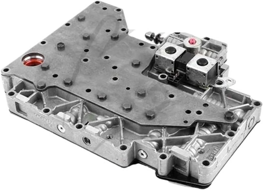
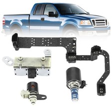
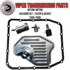
Cause 1: The 12-volt solenoid supply and the case connector
Before you buy a solenoid pack, prove the solenoids have power. On this family the shift, EPC and TCC solenoids all live on an internal hard wire frame that terminates at a case connector, and that connector is the most abused electrical component on the unit. Every rebuild pulls it. Every leak wicks fluid into it.
Transmission Digest documented a case that should be printed and taped inside the toolbox lid: a 4R70W came back from overhaul with a hard wire frame and case connector replacement, and on the first road test it took off in a higher gear with the MIL on and a spread of solenoid codes that were not there before the job. The cause was an aftermarket sub-standard case connector with two terminals pushed back far enough that they never made contact with the hard wire frame. One of those two was the 12-volt solenoid supply circuit — which is exactly why it took off in a high gear rather than throwing one clean circuit code. The fix was Ford original equipment parts: hard wire frame F8AZ-7G276-BA and connector F8AZ-7G276-A. Codes cleared and stayed gone.
How to check it in ten minutes, before the pan comes down:
- Key on, engine off, backprobe the solenoid feed at the case connector. Battery voltage should be present and should stay there while you wiggle the harness and the connector body.
- Pull the connector and look straight down into it under a light. A pushed-back terminal sits visibly lower than its neighbors, so compare pin heights side by side rather than judging any pin on its own.
- Check for fluid in the connector shell. Fluid there means the internal seal is done, and whatever you measure at the PCM is suspect.
- If the unit was recently apart, ask what brand of connector went in. A no-name connector a few thousandths off on terminal depth produces exactly the symptom above, and no amount of code reading will point at it.
Cause 2: EPC pressure is gone, and the solenoid is not the reason
When the PCM loses control of the electronic pressure control circuit, line pressure goes to its mechanical maximum and shift quality goes with it. Most techs handle it the same way: gauge on the line pressure port, EPC reads near zero at every throttle opening, replace the EPC solenoid, road test, problem still there.
Here is why. Wayne Colonna's teardown of this exact failure in Transmission Digest traces it to wear in the pressure regulator valve bore, not the solenoid. EPC pressure is routed to the pressure regulator valve alongside a circuit Ford calls the boost circuit, and that boost circuit is routed back to the inlet side of the pump. When the bore wears enough between those two circuits, EPC pressure is simply sucked away by the pump, and you get no line rise with throttle opening no matter how good the solenoid is. The article notes the condition frequently shows up hot, which is why the truck drives out of the bay fine and comes back on a hook.
There is a five-minute test for it that needs nothing but shop air. Drop the pan and filter, then blow compressed air into the TV pressure port. Air and fluid blowing out around the EPC solenoid area is normal, so do not chase that. Air and fluid blowing out of the filter opening is the bore wear.
Sonnax confirms the wear pattern from the parts side. Their tech bulletin on this family states it is common for the pressure regulator valve in 4R70W, 4R70E, 4R75W, 4R75E and AODE units to wear severely, with scoring on the EPC end of the valve producing reduced line pressure or low line rise. Their point about the repair is the one people skip: if the valve looks that bad, the bore is compromised too, and a new valve in a worn casting will not seal. Sonnax's answer is to vacuum test the bore, then ream and fit an oversized valve — kits 76948-16K for 1995-and-earlier and 76948-17K for 1996-and-later, with plain replacement valves 76948-01 and 76948-09 for bores that still test good. You can build the vacuum test tool yourself out of an old reverse boost sleeve: drill through the end, run a 1/4 inch tube in far enough to block the side feed holes, and pull vacuum through it with a good PR valve held inboard in the bore.
Colonna's original write-up predates those oversized kits and told readers to replace the valve body outright, which was correct at the time. With a reamer and a vacuum gauge the bore is repairable now; without them, a reman valve body is still the honest answer. The diagnosis has not changed: verify the bore before you spend money on a solenoid.
Cause 3: Gear ratio errors from a signal you cannot see on a scan tool
The PCM does not have a gear position sensor. It calculates which gear the unit is actually in by comparing turbine shaft speed to output shaft speed, then compares that number against the gear it commanded. When the two disagree by enough for long enough, you get a ratio code and a drop into failsafe. Divide TSS by OSS in a steady gear on a 4R75W and you should land near 2.84, 1.55, 1.00 or 0.70. Anything else is either a genuinely slipping element or a lying sensor.
Telling those two apart is where this gets interesting. Brian Kling walked through a case in Transmission Digest where a Ford turbine speed signal produced repeated ratio-driven events with no visible turbine speed dropout in the recorded scan data at all. The graphed data showed a drastic change in calculated gear ratio while commanded gear and actual gear never moved. His explanation is the part worth carrying to every Ford on your lift: scan tools sample at a limited rate, and a signal interruption can be far too brief to appear in scan data while still being long enough to wreck the PCM's ratio math.
The fix for that blind spot is a lab scope, and the procedure transfers directly to a 4R75W:
- Scope the shift solenoid drives first to rule out erratic solenoid control. If the solenoid patterns stay stable through the event, the fault is not in hydraulic command.
- Backprobe the TSS signal, power and ground at the PCM connector. On these Fords the TSS shares its power and ground with the output speed sensor and the transmission range sensor — so if TSS, OSS and range complaints show up together, suspect the shared supply, not three sensors.
- If the signal drops at the PCM, add a second probe at the sensor connector and compare the two waveforms during the same event. Clean at the sensor and dropping at the module isolates the fault to the wiring between them.
- Wiggle test in sections from the transmission back toward the PCM. In Kling's case the break was where the harness rested against an A/C line near the firewall pass-through, with nothing worse than light rub marks visible on the loom.
Two practical notes from my own bench. First, a magnetic pickup that reads but reads wrong under load is usually carrying clutch material on the tip, and that debris is your real diagnosis. Second, before you condemn anything electrical, put a light on the fluid. Low or aerated fluid drops line pressure, lets an element slip, and produces a real ratio error with a perfectly healthy sensor. The 4R75W runs MERCON V — do not put a low-viscosity fluid in it because it was on the shelf.
Cause 4: Valve body wear that sets ratio codes with no electrical fault
This is the category that gets misdiagnosed as "the computer." A shift valve that will not stroke, or a plug that leaks past, produces a gear the PCM did not command — and the PCM's only way to describe that is a ratio code and a trip to failsafe. Sonnax's vacuum test guide maps the wear locations on this valve body to complaints directly, and the overlap with limp symptoms is heavy:
| Valve | Complaints Sonnax lists |
|---|---|
| 1-2 and 2-3 shift valves | No 2nd, wrong gear starts, erratic shift timing, gear ratio codes |
| 2-3 shift valve end plug | No 2-3, poor 2-3 quality, no reverse, no 4th, gear ratio codes, burnt bands |
| 3-4 shift valve | No 4th, gear ratio codes |
| Solenoid regulator valve | Erratic shifts, 2-3 neutral, neutral after 4th, 3rd and reverse only, no 2nd |
| Bypass clutch control valve | Codes 628, 741, 1741, 1744, no lockup, TCC slip, burnt reverse clutch |
| Main pressure regulator and boost valve | Low line rise, soft shifts, erratic buzz, premature clutch and band failure |
Note the solenoid regulator valve row in particular: 3rd and reverse only. That is a mechanical complaint that presents on a road test exactly like an electrical failsafe. The way you separate them is the vacuum gauge on the bench, not the scan tool in the cab. Sonnax's own advice on this valve body is blunt — bore wear is often invisible to the naked eye, so when in doubt, vacuum test.
4R75W shift solenoid sets, EPC solenoids, filters and pan gaskets, Sonnax pressure regulator valve kits, line pressure gauge kits and MERCON V — shipped from the USA.
Shop 4R75W parts →The order I actually work a 4R75W limp complaint
- Verify the gear before you verify anything else. Road test and confirm whether the start gear is second. Second plus working reverse points electrical. Anything else points hydraulic or mechanical.
- Pull codes and freeze frame, then clear and re-drive. You want to know which code sets first on a clean slate, because ratio codes are downstream of almost everything.
- Check fluid level and condition hot. Aerated or burnt fluid changes the meaning of every pressure number you are about to take.
- Gauge on the line pressure port. Watch line pressure at idle in drive and at a brake-loaded throttle opening. Flat pressure with no rise is the EPC circuit; the question is whether it is electrical or the pressure regulator bore.
- Unplug the case connector and re-check. With the solenoids unplugged, the unit should go to maximum line pressure. If pressure does not rise even unplugged, the EPC solenoid is not your problem — go to the compressed-air test at the TV port.
- Verify 12-volt solenoid supply at the case connector before you condemn a solenoid pack, and inspect the terminal depths.
- Graph TSS, OSS and engine RPM together on a road test and run the ratio math against 2.84, 1.55, 1.00 and 0.70. If the scan data looks clean but the truck misbehaves, go to the scope.
- If it is coming apart, vacuum test the valve body. Reusing a worn PR bore is how a rebuild comes back.
Keeping it out of limp in the first place
Most of the 4R75W failsafe complaints I see trace back to three preventable things. Fluid that stayed in too long and cooked the shift valve bores. A case connector that got fluid in it and was never resealed properly. And a rebuild that reused a pressure regulator bore because the valve "looked fine." Service the fluid with MERCON V on a real interval, seal the case connector like it matters, and vacuum test the valve body every time it is on the bench. On a truck that tows, add the cooler to that list — heat cooks the fluid, soft fluid lets pressure fall, low pressure lets an element slip, and a slipping element is a ratio code.
Related reading: our 4R70W and 4R75W problem guide, 4R70W shift solenoid symptoms, the 4R70W valve body wear fix, and how to check line pressure.
Sources
- Gears Magazine (ATRA) — "Solenoid Application Charts," January/February 2006, page 77-78. Backs the 4R70W/AODE family being Shift Chart Type 3 and the full solenoid table used in this article: 1st SSA on / SSB off, 2nd both off, 3rd SSA off / SSB on, 4th both on — which is what makes second gear the both-solenoids-off failsafe state. atracom.blob.core.windows.net
- Transmission Digest — "Ford 4R70W solenoid codes set," Transmission Tech/Talk. Backs the high-gear start with new solenoid codes after a hard wire frame and case connector replacement, the sub-standard aftermarket connector with two pushed-back terminals including the 12-volt solenoid supply circuit, and the Ford OE part numbers F8AZ-7G276-BA (hard wire frame) and F8AZ-7G276-A (connector). transmissiondigest.com
- Transmission Digest — "I Lost My EPC!", Wayne Colonna, Technically Speaking. Backs the pressure regulator valve bore wear that reduces or eliminates EPC pressure when hot, EPC reading near zero at any throttle opening and with the transmission unplugged, the boost circuit routing back to the inlet side of the pump so that EPC pressure is drawn away, the compressed-air-into-the-TV-port test with fluid at the EPC solenoid being normal versus fluid out of the filter indicating bore wear, and the link to premature forward clutch wear. transmissiondigest.com
- Sonnax — "Watch Out for 4R70W Pressure Regulator Valve & Casting Wear," Brian Wing, November 2022. Backs the severe PR valve wear across 4R70W, 4R70E, 4R75W, 4R75E and AODE units, scoring on the EPC end producing reduced line pressure and low line rise, the compromised bore that a new valve alone will not fix, the reaming and oversized valve repair with kits 76948-16K and 76948-17K and replacement valves 76948-01 and 76948-09, and the reverse-boost-sleeve vacuum test tool procedure. sonnax.com
- Sonnax — "Ford 4R70E, 4R70W, 4R75E, 4R75W, AODE Vacuum Test Guide." Backs the valve-by-valve complaint table: gear ratio codes and wrong gear starts at the 1-2 and 2-3 shift valves, no 2-3 / no reverse / no 4th / gear ratio codes at the 2-3 shift valve end plug, no 4th at the 3-4 shift valve, "3rd and reverse only" plus 2-3 neutral at the solenoid regulator valve, codes 628, 741, 1741 and 1744 at the bypass clutch control valve, and low line rise with premature clutch and band failure at the main pressure regulator and boost valve. sonnax.com
- Transmission Digest — "Intermittent Turbine Speed Signal Failure," Brian Kling, R&R Tech. Backs the PCM calculating gear ratio by comparing turbine speed to output shaft speed, a drastic calculated-ratio change with no commanded or actual gear change, scan tools sampling too slowly to show a brief dropout that still disrupts PCM math, the TSS sharing power and ground with the output speed sensor and transmission range sensor, and the scope-at-sensor versus scope-at-PCM method that isolated a harness fault at a firewall pass-through with only light rub marks visible. transmissiondigest.com