Read the code definition slowly, because on this transmission it is the whole diagnosis. P0716 is "Input/Turbine Speed Sensor A Circuit Range/Performance." Not "circuit malfunction." Not "no signal." The PCM is getting a turbine speed number, it is a real number, and it is wrong — wrong relative to engine RPM, wrong relative to output shaft speed, or wrong relative to the gear the PCM just commanded.
That distinction sends you somewhere completely different than P0715 does. A circuit code says the signal path broke. A range/performance code says the signal path is fine and the mechanical world it is reporting on has stopped behaving. On a 5R55W, the mechanical world stops behaving in two very well documented ways, and neither of them is a sensor.
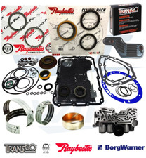

What P0716 Is Actually Comparing
The PCM does not evaluate turbine speed in isolation. It has engine RPM from the crank sensor, output shaft speed from the OSS, an intermediate shaft speed signal, and a commanded gear. From those it can predict what turbine speed ought to be. Torque converter slip explains a bounded gap between engine RPM and turbine speed. Gear ratio explains the relationship between turbine speed and output speed. When the measured turbine number will not fit inside either of those windows, the plausibility test fails and P0716 sets.
So ask the useful question: what makes turbine speed genuinely land outside the window? A clutch or band that is slipping. If the intermediate band is supposed to be holding and it is not, the turbine keeps spinning faster than the gear ratio says it should, the PCM's ratio math comes out between gears, and you get a performance code — usually with company. On this unit that company is normally a gear ratio error code, a pressure control solenoid code, or both.
ATSG's Pete Luban laid out that relationship in Transmission Digest using a 2002 Explorer with a 5R55W: no 2nd or 5th, ratio codes P0732 and P0735 stored, and P0775 for pressure control solenoid B alongside them. His point is worth memorizing. Of all the ATSG help line calls on gear ratio codes and on P0745, P0775 and P0975, they had yet to find a single instance where the solenoid code was electrically generated. These are performance codes. The solenoid is being blamed for a pressure it never got to deliver.
Cause 1: Servo Pin Bore Wear (Start Here)
Luban named it directly: the number one cause of both the solenoid performance codes and the gear ratio errors on the 5R55N, W and S is wear in the servo pin bore, and these units are notorious for wearing them severely, sometimes at genuinely low mileage.
Sonnax spells out the hydraulics of why. Servo apply oil is fed through the center of the case bridge and into the servo pin, reacting on the cover side of the piston. As the case pin bore wears, that apply oil leaks into the barrel area of the case, which hurts both shift timing and servo and band apply pressure. Release pressure comes through the case into the spring side of the piston, and as the wear increases, release oil cross leaks into the apply circuits and exhausts at the shift valves. In Reverse, both servos are charged from the release side, so pin bore wear also shows up as delayed Reverse.
Now put that back on the scan tool. A band that applies slowly, or applies against a leak, lets the drum keep turning through the shift. Turbine speed hangs high, the calculated ratio never settles where it should, and the PCM flags exactly what it is seeing: an input speed that does not perform. The sensor is telling the truth. Nobody wants to hear it.
The air-apply test that settles it
This is the ten-minute test that saves you from throwing a sensor at it, straight out of the ATSG article:
- Back the band adjustment stud way off so there is no tension on the band at all. Tension masks the leak.
- Make sure there is oil in the release side of the servo bore.
- Air apply the servo.
- Watch what blows out of the servo pin bore area of the case.
Luban's own words on the result: you will not believe how bad it can be. If air is whistling out around the pin, you have found your P0716 and you did not need a scope to do it. Sonnax makes a wear-resistant aluminum sleeve kit for exactly this, part number 56361J-01K, which repairs both the overdrive and the intermediate servo pin bore locations on the 5R55N, W and S and salvages a case that would otherwise be scrap. The tool kit pilot and reamer align from the pin bore centerline rather than the servo piston bore, which matters — that is the reference that actually controls pin fit.
Cause 2: VFS Modulator Bore Wear in the Valve Body
The second cause is the one that explains why so many of these come back after a solenoid pack. Sonnax's Bob Warnke, in "Figuring Out the 5R55 Alphabet," describes the wear order in a 5R55W/S valve body: the TCC modulator bore and the main regulator bore tend to wear first because they are the most active. Then, as cycle rate climbs — and it climbs hard in city traffic — the VFS 1, 2 and 3 modulator bores wear, reducing clutch and servo pressure.
Here is the part that matters for a code that takes years to show up. Ford's adaptive strategy compensates for that falling pressure for a long time. The truck drives acceptably while the valve body quietly gets worse. Then the adapts run out of authority, and in Warnke's words, gear ratio codes or slippage occur. His warning is the same as Luban's from the other direction: the solenoid or the servo pin bore gets blamed, but the actual cause is that the VFS modulator valves cannot supply enough pressure.
A worn bore is not something you can see. Vacuum test it, or wet air test it. Warnke recommends the wet air test as the effective method for judging 5R55N, W and S valve body condition, and it works in the vehicle or on the bench: a good valve body strokes its valves without excessive leakage past them or bubbling from the exhausts.
Sonnax VFS modulator valve kit 56947J-19K → or browse all 5R55W parts
Cause 3: Aerated Fluid and a Level You Cannot Trust
Sonnax notes something about this family that gets skipped constantly: the 5R55N, W and S are prone to foaming the fluid in the sump from excess exhaust and valve body wear, which results in fluid out the vent and improper fill indications.
Chase that through. Air in the fluid is compressible; oil is not. A clutch or band fed with aerated fluid applies soft and late, which is the same slip that sets P0716. Meanwhile the level reads full — or the unit has actually pushed fluid out the vent and is genuinely low, and you top it off against a false reading. Either way you are diagnosing a symptom of the leakage, not the leakage.
Fluid spec on this transmission is MERCON V, and there is history there too. Warnke documents that the factory fill in the 5R55E, W, S and N prior to May 2005 was an early MERCON V that degraded and took solenoids with it. Ford released an interim additive package, 4L2Z-19B546-AB, under bulletin FSA 04B22, and the final resolution was the revised MERCON V sold as XT-5-QM in the black quart container. The line most people skip: if you service one of these and leave any trace of the questionable fluid behind, you shorten the life of the next solenoid too.
Cause 4: The Sensor and Circuit (Rule It Out, Do Not Assume It)
It is still worth ten minutes to prove the signal is honest before you commit to hydraulics, and there is a right way to do it. ATRA's Keith Clark, writing in GEARS, points out that a permanent magnet speed sensor generates its own AC signal that grows in both magnitude and frequency with RPM, while a Hall effect sensor needs a supply voltage and produces a fixed-amplitude digital signal that only changes frequency. Some Hall sensors are two-wire and get mistaken for magnetic pickups on a visual inspection, so identify what you actually have before you interpret a reading.
His warning about method is the one that costs people days: a scan tool in graph mode averages the values, so it is easy to miss glitches or low signal output entirely. Intermittent dropout and noise are the common speed sensor failures, and you will normally only catch them with a graphing voltmeter or a scope monitoring the circuit directly — ideally right at the module, so you see what the module sees.
Two practical checks while you are there. Turbine speed in Park or Neutral with the engine running should read near engine RPM, because the converter turbine is being driven. And if the signal is clean everywhere except in specific gears, stop testing the sensor: a sensor fault does not know what gear you are in. Clark documented that exact trap on a Ford 6F55N where input speed fell to zero in 3rd and 5th only. Two brand new factory sensors behaved identically and the circuit pinpoint-tested good, because the snap ring holding the cast iron retainer — which is the reluctor wheel for the input speed sensor — had blown off the 3-5-reverse drum, and clutch apply pressure was pinning the retainer against the end cover so it could not turn. Something that only fails when a particular clutch or band applies is mechanical or hydraulic, every time.
Cause 5: Something Upstream Made the Unit Slip
Do not skip the engagement hydraulics, because a unit that engages badly slips on every takeoff. Rob Faucett walked a 2006 Explorer 5R55W through GEARS with a severe hot delayed forward engagement where only the forward clutches were burned — unusual on a transmission that normally shows servo pin wear, burnt bands and destroyed overdrive planets. His breakdown of forward engagement is worth knowing: the PCM modulates pressure control solenoid B at about 0.5 amps to stroke the forward engagement valve against its spring, opening a path from the VFS1 control valve to the forward clutch, while pressure control solenoid A operates VFS1 to control mainline flow into that clutch. Reduce current to solenoid A and pressure rises, acting on the spring side of the forward engagement control valve.
That chain has several places to leak, and a forward clutch that fills slowly is slip the PCM will absolutely see on the turbine PID.
The Diagnostic Order That Works
- Pull all codes, not just P0716. Ratio codes and pressure control solenoid codes stored with it are the strongest clue you will get.
- Read the freeze frame. Note gear, speed and fluid temperature — a fault that only sets hot points at clearance and leakage.
- Check fluid level and condition, and look for evidence of fluid pushed out the vent. Confirm MERCON V and that the early degraded fill is long gone.
- Scope the turbine signal at the case connector, not on the scan tool. Confirm it is stable under load and at low speed.
- Graph turbine RPM against output RPM on a road test and divide for the live ratio. Note which gears it fails in.
- Fails only in specific gears? Go straight to the clutch or band that holds those gears.
- Air-apply test the servos with the band tension backed off. Watch the pin bore.
- Wet air test or vacuum test the valve body, VFS1 and VFS2 modulator bores and main regulator bore included.
- Only after all of that does a solenoid pack or a sensor become a reasonable purchase.
- Prime replacement VFS solenoids with fresh fluid before installation and run an adaptive relearn afterward. Ford units built after 2002 use adaptive strategy, and skipping the relearn leaves the old compensations in place.
Shop 5R55W servo kits, valve body kits, solenoid packs, bands, filters and full rebuild kits — shipped fast from the USA.
Shop 5R55 parts →FAQ
What is the difference between P0715 and P0716 on a 5R55W?
P0715 is a circuit code: the PCM cannot get a usable signal at all. P0716 is a range and performance code: the signal is arriving and the PCM is reading a number, but that number does not agree with engine speed, output speed and the gear it commanded. Because the signal is present, P0716 far more often points at something mechanical or hydraulic that made the turbine genuinely turn at the wrong speed than at a dead sensor.
Can servo pin bore wear cause a speed sensor code on a 5R55W?
Yes, indirectly, and it is the most common reason on this unit. ATSG's Pete Luban wrote in Transmission Digest that the 5R55N, W and S are notorious for severely wearing the servo pin bores and named that wear the number one cause of the gear ratio error codes and pressure control solenoid performance codes on these transmissions. Sonnax describes the mechanism: as the pin bore wears, servo apply oil leaks into the barrel area of the case and release oil cross leaks into the apply circuits, which hurts shift timing and band apply pressure. A band that applies late lets the turbine overspeed, and the PCM sees an input speed that does not match the gear.
How do I test a 5R55W servo pin bore?
Back the band adjustment stud way off so there is no tension on the band, make sure there is oil in the release side of the servo bore, then air apply the servo and watch what blows out around the servo pin bore area of the case. That is the ATSG procedure, and the leakage is often severe at surprisingly low mileage. Sonnax sells a wear resistant aluminum sleeve kit, part 56361J-01K, that repairs the overdrive and intermediate servo pin bores in the 5R55N, W and S instead of scrapping the case.
Why does my 5R55W read low on fluid but keep foaming?
Sonnax documents that the 5R55N, W and S are prone to foaming the fluid in the sump from excess exhaust and valve body wear, which pushes fluid out the vent and gives improper fill indications. Aerated fluid is compressible, so clutch and band apply gets soft and slow, the unit slips, and the turbine speed the PCM reads stops matching the commanded gear. Fix the leakage that is causing the foam before you chase the level.
Will replacing the turbine speed sensor fix P0716?
Only if the sensor or its circuit is actually at fault, which is the minority of cases on this transmission. Check the case connector and scope the signal first, because GEARS notes that a scan tool averages speed values and will hide brief dropouts that a graphing meter or scope catches. If the signal is clean and stable and the code still returns, stop buying sensors and start testing hydraulics.
Working a 5R55W this week?
Servo piston kits, valve body kits, solenoid packs, filters, bands and full rebuild kits — shipped fast from the USA.
Shop 5R55 parts →Sources
- Transmission Digest — "False Pretenses," Pete Luban, ATSG Technical Supervisor, February 1, 2005. Backs the core argument of this article: on a 2002 Explorer 5R55W with no 2nd or 5th, ratio codes P0732 and P0735 were stored alongside P0775; ATSG had yet to find an instance where a gear ratio code or a P0745, P0775 or P0975 was electrically generated; wear in the servo pin bore is the number one cause of these solenoid performance and gear ratio error codes on the 5R55N, W and S; and the air-apply test procedure with the band adjustment stud backed off. transmissiondigest.com
- Sonnax — "Figuring Out the 5R55 Alphabet," Bob Warnke, September 19, 2007. Backs the valve body wear order and the fluid history: the TCC modulator bore and main regulator bore wear first due to activity, then the VFS 1, 2 and 3 modulator bores wear and reduce clutch and servo pressure until adaptive strategy runs out and gear ratio codes or slippage occur; the factory fill prior to May 2005 was an early MERCON V that degraded solenoids, addressed by interim additive 4L2Z-19B546-AB under bulletin FSA 04B22 and finally by the revised MERCON V sold as XT-5-QM; and the wet air test as the method for judging valve body condition. sonnax.com
- Sonnax — Overdrive & Intermediate Servo Pin Bore Sleeve Kit 56361J-01K, product and cause data. Backs the servo hydraulics and the repair: apply oil is fed through the center of the case bridge into the servo pin and reacts on the cover side of the piston, so pin bore wear leaks apply oil into the barrel area and cross leaks release oil into the apply circuits, hurting shift timing and band apply pressure and delaying Reverse; the 5R55N, W and S are prone to foaming fluid in the sump from excess exhaust and valve body wear, causing fluid out the vent and improper fill indications; and the kit's listed symptoms include 1-2, 2-3 and 4-5 flares and codes 732, 733 and 735. sonnax.com
- GEARS Magazine (ATRA) — "Sensing Problems: A Look at Common Sensor Failures," Keith Clark. Backs the sensor testing method: permanent magnet sensors generate an AC signal that increases in magnitude and frequency with RPM while Hall effect sensors need a supply and produce a fixed-amplitude digital signal, and some Hall sensors are two-wire and get mistaken for magnetic pickups; a scan tool in graph mode averages values, so glitches and low signal output are easy to miss; intermittent dropout and noise are the common failures and are best caught with a graphing voltmeter or scope monitoring the circuit at the module; speed sensor failures usually cause no shifts or failsafe operation, sometimes without codes. gearsmagazine.com
- GEARS Magazine (ATRA) — "Going Nowhere Fast... 5R55W Delayed Forward Engagement," Rob Faucett, September 1, 2017. Backs the forward engagement hydraulics and the typical failure picture: a 2006 Explorer 5R55W with severe hot delayed forward engagement where only the forward clutches were damaged, which is rare because these units normally show servo pin wear, burnt bands and destroyed overdrive planets; the PCM modulates pressure control solenoid B at about 0.5 amps to stroke the forward engagement valve against its spring, opening a path from the VFS1 control valve to the forward clutch, while pressure control solenoid A operates VFS1 to control mainline flow. gearsmagazine.com
- GEARS Magazine (ATRA) — "The Disappearing Input Speed Sensor Signal," Keith Clark. Backs the "signal dies only in specific gears" rule: on a Ford 6F55N, input speed dropped to zero in 3rd and 5th only, two brand new factory sensors behaved identically and the circuit pinpoint-tested good, because the snap ring holding the cast iron retainer that serves as the input speed sensor reluctor had blown off the 3-5-reverse drum and clutch apply pressure was stopping the retainer from rotating. gearsmagazine.com