A 6.7 Cummins RAM comes in with a check engine light and a complaint that it pulls away like it is in the wrong gear. You plug in and there it is: P0731 — Gear Ratio Error in 1st. P0731 does not name a broken part. It reports a math problem, and on the 68RFE there is a short, specific test sequence that turns that math problem into a part number.
For more on Dodge and RAM transmissions, visit our Dodge transmission hub and RAM transmission hub.

What the TCM Is Actually Measuring
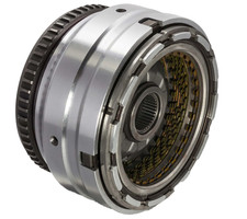
The 68RFE runs two speed sensors. The input speed sensor reads 60 teeth off the input clutch hub; the output speed sensor reads 30 teeth off the park gear. Divide input rpm by output rpm and you get the ratio the transmission is actually delivering right now. The controller knows what gear it commanded and what that gear should produce. Per FCA's published 68RFE specification table, first gear on this unit is 3.231:1 (then 1.837, 1.410 and 1.0 through fourth, a 5.16:1 overall ratio spread), so with 1st commanded the controller expects input speed to be roughly 3.23 times output speed.
The factory set condition is blunt: the code sets "if the ratio of the Input rpm to the Output rpm does not match the current gear ratio," monitored continuously with the engine running (per the FCA RFE-family P0731 diagnostic chart). It also notes the DTC "can take up to five minutes of problem identification before illuminating the MIL." That delay matters in the bay. A customer can drive a slipping truck for several minutes before the light comes on, which is why the complaint and the code often do not line up in time.
Those tooth counts matter for one more reason: if the common speed sensor ground circuit is lost, both inputs read pulses from the input speed sensor and the 60/30 difference produces an apparent 1:2 speed ratio, which typically sets P1794 rather than a clean ratio code. That is a wiring repair, not a transmission repair.
The Rule That Trips Up Most Techs
Read this line from the factory chart carefully, because it reverses the assumption most people bring to a ratio code: gear ratio DTCs "will set only if the transmission slips after first achieving the correct ratio. Therefore, a transmission with no drive (or reverse) may not set any Gear Ratio Error DTC because it never achieves a correct gear ratio."
In other words, P0731 is a slip code, not a no-first-gear code. A truck with a completely dead underdrive circuit can come in with no P0731 stored at all. And the flip side is just as useful: if you do have P0731, the unit made a correct 3.23:1 at some point, then lost it. That is a clutch that holds and then lets go, or a hydraulic circuit that fills and then bleeds down — not a circuit that never filled.
What Actually Holds First Gear on a 68RFE
The 68RFE is built around three planetary gearsets and, per FCA's own specification table for the unit, one overrunning clutch under full electronic control. In first gear the underdrive (UD) clutch is the driving member, and the reaction is split: the low/reverse clutch holds at a standstill and for engine braking, while the overrunning clutch carries the reaction load once the truck is moving and the low/reverse solenoid drops out.
ATSG's 68RFE clutch application chart puts a number on that hand-off: in Drive, 1st is UD plus L/R, but the L/R clutch is on only while output shaft speed is below 150 rpm. Above that the low sprag carries the reaction by itself. In manual 1st, L/R stays applied for engine braking. The L/R pressure switch on the solenoid pack follows the same rule, and per ATSG the switches close at 23 psi and open at 11 psi, so watching the L/R switch state on the scan tool shows you exactly when the TCM released L/R. If the ratio error shows up right as that switch opens, look at the sprag. If it is there from a standstill with the switch closed, look at UD. (For slip in other gears, the same chart logic is laid out in our 68RFE slipping guide.)
That hand-off is the whole diagnostic story on P0731. There are two completely different failures that both produce a 1st gear ratio error:
- The UD clutch is slipping. The input side spins faster than the geartrain is carrying. Ratio goes wrong immediately, including from a dead stop with the brakes on.
- The overrunning clutch has failed and rotates in both directions. The truck holds fine while low/reverse is applied, then neutrals out the instant it releases and the overrunning clutch is supposed to take over.
Those feel identical to the customer and are nowhere near the same repair. You can separate them in about two minutes without removing anything.
The Two-Minute Test That Splits It
Work the factory sequence in order. It is fast and it keeps you from condemning a good clutch pack.
- Pull every code, not just P0731. If any transmission solenoid, line pressure, speed sensor, or loss of prime DTCs are present, chase those first — they can cause a speed ratio error on their own. If P0944 (loss of prime) is stored, it goes to the front of the line.
- Check L/R Clutch State. Engine running, brakes firmly applied, truck stationary, selector in Drive. L/R Clutch State should read Applied. If not, cycle the ignition off at least 30 seconds and retest; if it still will not read Applied, inspect PCM terminals for corrosion, damage and push-out — power and grounds especially — before you touch the transmission.
- Run the 1st Gear Clutch Test. With the scan tool driving the test, bring throttle angle to 30 degrees for no more than a few seconds. Input speed must remain at zero. If it climbs, the underdrive clutch is slipping and the unit is coming apart. Do not sit in this test — you will overheat the transmission.
- If that test passes, check the overrunning clutch. Launch the truck from a stop in 1st while watching L/R Clutch State. If the transmission neutrals out the moment L/R Clutch State changes to Not Applied, the overrunning clutch has failed and rotates in both directions. That is a teardown.
- If nothing acts up, read Event Data. The conditions are not currently present, so let the recorded data tell you what was true when the code set.
Reading the Event Data Like the Factory Does
This is the part most shops skip, and it is where a P0731 gets solved without a rebuild. The factory chart gives four branches straight off the recorded snapshot:
- P0731 set in Park, Reverse, or Neutral. The transmission was not even in 1st. Replace the powertrain control module.
- P0731 set with input rpm = zero. The sensor lied, not the clutch. Check the input speed sensor and its wiring.
- P0731 set with line pressure significantly below desired line pressure. Go find the cause of low pressure: fluid level, a mis-installed or damaged primary filter or filter seal, or a sticking main regulator valve in the pump.
- P0731 set with the UD pressure switch open while line pressure matched desired. The pump made pressure and the underdrive circuit did not hold it. Air check the UD hydraulic clutch circuit for leakage. If that circuit checks out, replace the solenoid and TRS assembly.
Check the gearshift linkage adjustment too, and keep in mind ratio DTCs can be set by extreme hot or cold conditions — ask whether the complaint only shows up on a cold morning or after a long grade in the heat. For intermittents, the factory approach is to pull the ignition switch feed fuse from the TIPM (mandatory, so the truck cannot be started in gear), install transmission simulator 8333, and wiggle wiring and connectors while watching for the fault.
Where the Underdrive Circuit Leaks
When the Event Data points at the UD circuit rather than the clutch itself, these are the places pressure goes missing on an RFE.
Checkballs in the UD Feed
Sonnax documents checkball No. 2 as the ball that keeps full line pressure from bypassing the UD solenoid feed to the UD clutch. Leave it out and you get harsh Neutral-to-Drive engagements plus a bind because the UD clutch cannot disengage, often with P0876 pressure switch rationality along for the ride. On 2019-and-later valve bodies, checkball No. 8 is unseated on apply and seated on release so the UD solenoid controls UD clutch release. If a P0731 shows up right after a valve body job, count your checkballs and confirm your separator plate and gasket orientation before blaming hard parts.
Solenoid Switch Valve and Plug Wear
Sonnax calls the solenoid switch valve plugs arguably the weakest link in the RFE valve body. They cycle constantly, wear the casting, and crossleak into and out of adjacent circuits, costing clutch apply pressure. Vacuum testing the bore is the reliable way to find it; where wear is severe, ream and fit an oversized valve rather than reassembling and hoping the slip goes away. The thin OE separator plate sealing against a rough casting is worth a look on the same teardown.
Dribbler Orifices in the Reaction Shaft Support
The factory cause list for P0731 specifically names a broken or missing dribbler orifice assembly in the reaction shaft support. GEARS Magazine describes what these actually do: dribbler valves are pressed into the stator support with an orifice, checkball and spring, and they let a small amount of fluid into the drum to keep the circuit pre-charged. If the orifice is missing, too much fluid gets in and partially applies clutches; if it is restricted, apply is slow and the clutch drags. Either way you are outside the fill timing the calibration assumes. While you are in there, check the bushings supporting the input drum — wear there lets the stator support contact and groove the hub, creating one more leak path.
Verify Line Pressure With a Gauge, Not Just the Sensor
Scan data is only as good as the transducer reporting it, and a failed line pressure sensor can hide a real pressure problem. Sonnax points to OE line pressure adapter tool No. 8259, which installs into the case in place of the sensor so the sensor and a mechanical gauge can both be fitted — confirming actual main line pressure and the sensor accuracy in one shot.
What You Find Inside
When P0731 does mean the unit comes apart, the factory list of likely causes in FCA's RFE P0731 chart is short and specific: cut UD piston seal, failed overrunning clutch, burned UD clutch, cut UD accumulator seal ring, broken UD accumulator piston, low line pressure, broken or missing main valve body bleed orifice, broken or missing dribbler orifice assembly in the reaction shaft support, poor machining on the pump valve body face, and the solenoid/TRS assembly itself. If line pressure codes were stored with the P0731, inspect the primary oil filter and seal, the transmission oil pump, and the main regulator valve as part of the job.
Two rules from the same chart are easy to miss and expensive to skip. First: if P0875 or P0876 were stored alongside P0731, replace the transmission solenoid and TRS assembly in addition to the internal repair. Second, and more important: if the UD clutch has failed and you cannot identify an obvious cause — no cut piston seal, no broken seal ring, no low line pressure in Event Data, nothing on the list — replace the solenoid and TRS assembly anyway. An unexplained burned UD clutch means the apply was wrong, and putting new frictions behind the same solenoid pack buys you the job back.
Building the Underdrive Pack Right
The UD clutch on the 68RFE is a single-sided stack. Per Raybestos Powertrain's instructions for its 68RFE underdrive kit, the pack builds as ten single-sided frictions — five OD-splined and five ID-splined, alternating, all with the material facing up — and the finished clutch pack clearance spec is 0.040 to 0.068 in (1.02 to 1.72 mm). Check it with a dial indicator while applying the clutch with 20 psi of air, not by feel and not with a feeler gauge alone. Clearance on the loose side lets the pack slip on apply and takes you right back to a ratio code; too tight drags the pack and cooks it. Pre-soak the frictions in the same ATF+4 the unit will run.
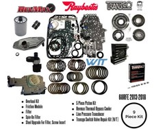
68RFE Friction Clutch Module Kit
If the 1st Gear Clutch Test showed input speed climbing off zero, the underdrive frictions are done. This is the complete friction module for 2007-up 68RFE builds — the right stack to put 1st gear back where the calibration expects it.
See the 68RFE friction clutch kit →Need seals, pistons, solenoids or a full overhaul kit instead? Browse the whole 68RFE parts collection.
Matching the Fix to the Finding
- 1st Gear Clutch Test failed (input speed rose): the UD clutch is slipping. Teardown, new UD pack set to spec, and find out what starved it.
- Neutrals out when L/R goes Not Applied: failed overrunning clutch. Teardown and replace.
- UD pressure switch open with line pressure at desired: air check the UD circuit; if it holds, replace the solenoid and TRS assembly.
- Line pressure below desired in Event Data: fluid level, primary filter and seal, or a sticking main regulator valve. Verify with a mechanical gauge through adapter 8259.
- Input rpm at zero in Event Data: input speed sensor and wiring. No teardown.
- Code set in Park, Reverse, or Neutral, or L/R Clutch State never reads Applied: PCM terminals and circuits first, then the module.
- Fresh valve body work in the history: checkball count, separator plate, gasket orientation, and casting-to-year match.
After any internal repair, run the quick learn so the controller re-adapts pressure and shift timing to the new parts, then run the 68RFE transmission verification test before the truck leaves. Refill with Mopar ATF+4 in stages and set the final level at operating temperature; our 68RFE fluid type and capacity guide has the service and dry-fill numbers.
Need parts for this job?
Underdrive frictions and steels, bonded pistons, seal kits, solenoid blocks, speed sensors, filters and ATF+4 — everything a P0731 repair asks for, in one place, shipped fast from the USA.
Shop 68RFE parts →FAQ
What does P0731 mean on a 68RFE?
P0731 is Gear Ratio Error in 1st. The transmission control module divides input shaft speed by output shaft speed and compares the result to the 3.23:1 first gear ratio the 68RFE is supposed to be producing. If the measured ratio does not match while 1st is commanded, it logs P0731. The factory chart notes the code can take up to five minutes of problem identification before it turns the light on, so the truck may drive badly for a while before you see it.
Why did my no-drive 68RFE not set a gear ratio code?
Because gear ratio DTCs only set if the transmission slips after first achieving the correct ratio. That is stated directly in the factory diagnostic chart. A unit with no drive never reaches a correct 1st gear ratio, so it never arms the monitor and may store no ratio code at all. Absence of P0731 is not evidence that 1st gear is healthy.
Is P0731 the underdrive clutch or the overrunning clutch?
It can be either, and there is a specific test that separates them. Run the scan tool 1st Gear Clutch Test with the brakes locked and bring throttle angle to 30 degrees briefly. If input speed climbs off zero, the underdrive clutch is slipping. If that test passes, launch the truck while watching L/R Clutch State. If it neutrals out at the moment L/R goes to Not Applied, the overrunning clutch has failed and rotates in both directions.
Can a speed sensor set P0731 with good clutches?
Yes. The ratio is only as honest as the two sensors feeding it. The input speed sensor counts 60 teeth on the input clutch hub and the output speed sensor counts 30 teeth on the park gear. If Event Data shows P0731 set with input rpm at zero, check the input speed sensor and its wiring before you open the transmission. A lost common speed sensor ground produces an apparent 1:2 ratio and typically sets P1794.
Do I have to replace the solenoid pack when I fix a burned underdrive clutch?
The factory repair note says yes when no other cause is found. If the underdrive clutch is burned and you cannot point to a cut piston seal, a broken accumulator seal ring, low line pressure in Event Data, or another item on the cause list, replace the transmission solenoid and TRS assembly along with the internal repair. It is also required if P0875 or P0876 were stored with the P0731.
Sources
- FCA/Chrysler 45RFE/545RFE service information, P0731 GEAR RATIO ERROR IN 1ST diagnostic chart (2007 Jeep Commander workshop manual, Section 21). The RFE family shares this control logic and chart with the 68RFE. Backs the theory of operation and the set condition that the code sets when input-to-output rpm ratio does not match the current gear ratio, monitored continuously with the engine running in gear; the five-minute problem-identification delay before the MIL; the 60-tooth input clutch hub and 30-tooth park gear sensor counts and the lost common ground 1:2 apparent ratio that sets P1794; the instruction to address solenoid, line pressure, speed sensor and loss-of-prime DTCs first; and the internal cause list of cut UD piston seal, low fluid, cracked or misinstalled primary oil filter or seal, stuck main regulator valve, failed overrunning clutch, cut UD accumulator seal ring, broken UD accumulator piston, broken reaction shaft support seal ring, low line pressure, broken or missing main valve body bleed orifice, broken or missing dribbler orifice assembly, poor machining on the pump valve body face, input speed sensor and wiring, and the solenoid/TRS assembly. The 68RFE-specific L/R Clutch State check, 30 degree 1st Gear Clutch Test and Event Data branches are from the FCA 68RFE service information for the 2009 RAM 3500 HD 6.7L. jeep.automotive-manuals.com (FCA 45RFE/545RFE P0731 chart)
- Stellantis North America (FCA) media release, “Dodge Introduces Cleaner, Quieter and More Powerful 6.7-liter Cummins Turbo-Diesel Engine,” 68RFE transmission specification table. Backs the published 68RFE gear ratios used to calculate the expected 1st gear ratio (1st 3.231, 2nd 1.837, 3rd 1.410, 4th 1.0, 6th 0.625, Reverse 4.444), the 5.16:1 overall ratio spread, and the factory description of the unit as three planetary gearsets with one overrunning clutch, full electronic control and an electronically controlled converter clutch. media.stellantisnorthamerica.com
- Sonnax, “Chrysler RFE Valve Bodies: Understanding Checkball Locations & Function”. Backs checkball No. 2 separating the underdrive solenoid feed from full line pressure (its absence causes harsh Neutral-to-Drive engagement, a bind because the UD clutch cannot release, and possible P0876), and checkball No. 8 on 2019-and-later valve bodies letting the UD solenoid control UD clutch release. sonnax.com
- Sonnax, “Troubleshooting 68RFE OD Clutch Failure: What to Check First”. Backs solenoid switch valve and plug bore wear producing crossleaks and clutch pressure loss, verification of main line pressure with OE line pressure adapter tool No. 8259 installed in place of the line pressure sensor, warping of the solenoid conductor plate bleeding apply pressure out of the circuit, and the thin OE separator plate sealing poorly against a rough casting. sonnax.com
- GEARS Magazine (ATRA), “68RFE OD Clutch Failure: Part 2”. Backs the dribbler valves pressed into the stator support with an orifice, checkball and spring that pre-charge the drum circuit, what a missing versus restricted orifice does to clutch apply, and input drum bushing wear cutting grooves in the hub that create additional leak paths. gearsmagazine.com
- Raybestos Powertrain, 68RFE Underdrive Clutch Torqkit RTK-6801 installation instructions. Backs the underdrive clutch pack build: ten single-sided friction plates alternating five OD-splined and five ID-splined, and a clutch pack clearance spec of 0.040 to 0.068 in (1.02 to 1.72 mm) measured with a dial indicator while applying the clutch with 20 psi of air. raybestospowertrain.com
- ATSG (Automatic Transmission Service Group), Dodge Ram Trucks 68RFE Transmission Technical Service Information (2011). Backs the clutch application chart showing 1st gear as UD plus L/R with the L/R clutch on only below 150 rpm output shaft speed in Drive, the low sprag as the single freewheel, and the five clutch-circuit pressure switches that close at 23 psi and open at 11 psi. atsg.biz (PDF)
Shop 68RFE clutch parts →
Related 68RFE guides
- 68RFE P0736: Reverse Incorrect Gear Ratio - Causes, Diagnosis, and Fix
- 68RFE P0871: Pressure Switch Rationality and What It Really Means
- 68RFE P0700: Transmission Control System Malfunction Explained
- 68RFE Valve Body Problems: Symptoms, How to Test, and Replacement
- 68RFE Rebuild Guide for RAM 2500/3500 Cummins: What Fails and How to Fix It