A 700R4 shudder shows up as a fine, fast vibration at steady cruise, usually in overdrive on light throttle, that clears the instant the driver touches the brake pedal or rolls into the throttle. Owners describe it as rumble strips, a rough tire, or a bad U-joint. It is none of those, and it is usually not a worn-out converter either.
What makes this unit easier to diagnose than a modern one is also what makes techs misread it. The 700R4 and the non-electronic 4L60 do not modulate the converter clutch. There is no duty-cycled solenoid feathering apply pressure and no controlled-slip strategy in the calibration. The clutch is commanded on or off. That means a shudder on a 700R4 is never normal controlled slip feeling a little rough. It is a clutch that is trying to hold and cannot. That single fact cuts the suspect list down to four things.
How the Clutch Actually Applies, and Why It Matters
Sonnax TASC Force member Ed Lee's write-up on troubleshooting lockup issues gives the mental model worth keeping: treat the lockup converter as a one-way valve, or if your background is electrical, as a diode. Charge and TCC release oil exits the input/turbine shaft, travels between the TCC piston and the converter cover, passes the outer diameter of the piston, and exits the converter. From there it goes through the cooler and re-enters the transmission as lube oil.
When the TCC control valve strokes to apply, that flow reverses. The piston is pushed forward until it contacts the cover, and the piston itself blocks the flow. The passage that used to be the exit now carries apply oil, and at the same time the passage through the input shaft opens to exhaust.
Now the line that explains most 700R4 shudders. Per that same Sonnax article, if the converter is full, lockup will begin to apply as soon as the release oil is opened to exhaust — even if no apply oil is entering the converter — because the normal working pressures inside the converter are always trying to push the piston toward the cover.
Read that backwards and you have your diagnosis. The clutch does not need a large apply pressure to start grabbing. It needs the release side to get out of the way, fully and quickly. Anything that lets release oil linger behind the piston, or that lets apply signal bleed off partway, gives you a piston that is neither released nor clamped. It rides on a film, sticks, slips, sticks again. That stick-slip cycle is the shudder the customer feels in the seat.
First, Prove It Is the Converter Clutch
Most of these vehicles are pre-OBD-II, so there is no slip PID and no code to lean on. There is something better: a vacuum gauge. Ed Lee's rule is clean — a TCC shudder does not affect manifold vacuum, but any engine performance problem does. Tee a gauge into a manifold vacuum source, run the vehicle to the speed where the complaint happens, and watch the needle during the event. A steady reading through the shudder means the shudder is TCC related. A needle that flutters or drops in time with the vibration means you are chasing a misfire, not a converter.
On a later 4L60E or a vehicle with OBD-II, ATRA's Gears Magazine adds the other half: pull generic Mode 6 misfire counts. If the per-cylinder count climbs every time you feel the shudder, you have found your culprit. Swap the suspect coil and plug to another cylinder; if the misfire follows the part, the part is the problem.
Gears also gives a useful speed filter: a shudder in the 35 to 45 mph range in 3rd or 4th is a strong candidate for converter clutch engagement. On a 700R4 that maps to lockup in overdrive on a light grade, which is exactly when the clutch is asked to hold torque with the least apply help.
Before you drive it, ask the questions Ed Lee asks: does the shudder happen on throttle tip-in, when climbing a grade, or only on steady cruise? And was anything done to the vehicle right before it started — a fluid service, an overhaul, even a brake job? Tip-in and grade shudders point at clamping force. A shudder that appeared the week after a rebuild points at something the last shop touched.
The Four Faults That Cause It on This Unit
1. TCC apply valve bore wear in the pump cover
This is the number one hydraulic cause in the 700R4 family, and it lives in the pump, not the valve body. Sonnax describes it directly for the GM TH200-4R, 4L60 and 4L60-E: excessive pump bore-to-valve clearance allows TCC signal oil to leak past the spool, preventing lockup or causing lockup to disengage when hot. Converter feed can also leak past that clearance, combine with signal oil, and cause premature lockup.
The failure modes Sonnax lists are worth memorizing because they are exactly what walks in the door: no lockup, falls out of lockup when hot, lockup immediately after 2nd gear, fluid blown out the fill tube. And the one that produces shudder specifically — oil cross-leaks may float the valve into a mid-way position, which restricts cooler flow and burns up the converter. A valve sitting halfway is a clutch applying halfway.
Sonnax also notes that with enough wear the solenoid ends up with no control over the valve's position at all, because converter feed oil leaking past the spool plus orificed signal oil is more than the solenoid can exhaust. That can stroke the valve fully into lockup and create a no-power or no-brake-cancel condition, where the engine bogs or stalls as the driver comes off the throttle.
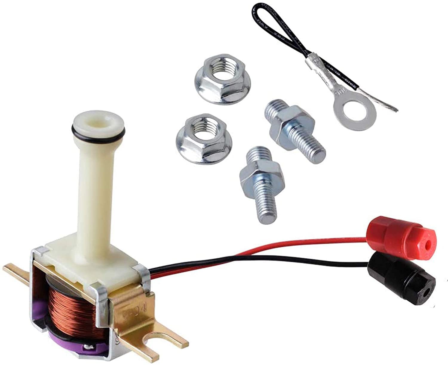
2. A cracked TCC solenoid snout
The 700R4 and pre-1997 4L60E use a plastic solenoid snout that cracks where it contacts the plunger valve. Per Sonnax, that crack leaks oil that should be directed to the converter clutch apply valve, and the listed symptoms are TCC apply concerns, overheated converter, and loss of lube oil.
This is a partial-signal fault, which is why it shudders rather than simply failing to lock. The solenoid is doing its job electrically; the oil it is supposed to route is going out the crack. Inspect the snout any time the pan is off for a lockup complaint — it costs nothing to look and it is the cheapest fix on this list. The aluminum replacement snout (Sonnax 77942-01K for the 4L60 and 1996-and-earlier 4L60-E) does not crack.
3. A restricted release and exhaust passage
If apply pressure is fine and the clutch still shudders, the oil behind the piston is not getting out fast enough. Ed Lee's point here is the one most techs never consider: when that exhaust passage is restricted, the oil trapped between the TCC piston and the cover cannot evacuate quickly enough for a good apply, and the condition has the same effect as weak apply pressure. That passage runs through the turbine shaft, pump, transmission case and valve body, and in some cases is up to 13 inches long. Thirteen inches of opportunity for a nick, a misaligned gasket, or a passage crushed during assembly.
4. Low or unstable line pressure
The 700R4 sets line pressure from the TV cable, and a slack cable starves the whole unit, converter charge pressure included. Install a line pressure gauge alongside a cooler flow meter and read them together. Sonnax's rule: if line pressure is low when flow is low, you have a wear issue in the pump or pump circuit. If line pressure is high when flow is low, the pressure regulator valve is being stroked out of balance. Either way, confirm and correct TV cable adjustment before you condemn a converter.
Universal Transmission Front Pump Remover (replaces T-0033 / J-45053)
The 700R4 TCC apply valve lives in the pump cover, so every hydraulic repair on this list starts with getting the pump out square and undamaged. A proper slide-hammer puller pulls GM, Ford and Chrysler pumps evenly and protects the sealing surfaces you are about to vacuum test.
See the pump remover →The Road-Test Sequence That Isolates It
Do these in order and you will not buy a converter you did not need.
- Vacuum gauge during the event. Steady vacuum means TCC. Unsteady means engine. Stop here if it is the engine.
- Verify fluid and friction material. Sonnax puts this before any gauge work: confirm the correct ATF is in it and that the converter clutch has the correct friction material for the application and apply strategy. A converter built for a modulated apply strategy sitting behind a non-modulated 700R4 is a shudder generator.
- Pressure gauge plus cooler flow meter. If cooler flow is normal but transmission pressure is lower than normal during the shudder, the shudder is a clamping force problem. Go to line pressure and the TV cable.
- Loop the cooler lines. Connect the outlet line straight back to the inlet at the transmission, bypassing the lines and the cooler. If the shudder goes away, the restriction is in the lines or the cooler. If it is still there, the restriction is upstream of the TCC piston.
- Replace the converter to split inside from outside. If the shudder is gone, the problem was inside the converter. If it survives a new converter, the restriction is in the exhaust passage, which puts you back at fault #3.
One more isolation trick from the same source: block the TCC control valve in the apply position. If the engine stalls when the shifter is moved into any drive range, the converter clutch itself is capable of holding, and your fault is on the control side.
The Bench Repair
Pull the pump and lay the OE TCC apply valve next to the replacement before you do anything else. Count the spools. Sonnax's instruction sheet for 77805-K is explicit: a double spool at the indicated location means a non-PWM valve, which is what a 700R4 has. A single spool means a PWM unit and requires 77805E-K instead. Do not use valve material to decide — some early PWM pumps used steel TCC valves. Mismatching PWM and non-PWM valves will cause rapid converter failure.
Installation is short. Discard the OE valve; keep the OE springs, valve stop and retaining clip. Fit the PTFE seal into the groove on the end of the Sonnax valve, lubricate it, and resize the seal by carefully inserting the valve backward into the outer portion of the bore and stroking it several times. Install the springs and valve with the seal end outboard, reinstall the valve stop, and set the retaining clip with the rounded edge facing the stop.
Then test it. Sonnax specs a minimum of 18 in-Hg at the indicated ports — one port tested with the valve stroked outboard and the orifice on the back sealed, the other with the valve blocked inboard and the bore opening sealed with your thumb. Anything under 18 in-Hg means the bore is leaking and the valve goes in.
And one warning that catches experienced builders. A common shop modification is to enlarge the TCC signal orifice in the pump to help the valve stroke completely on apply. Sonnax says do not do that when running their valve — the increased oil flow can flood the TCC solenoid and produce uncontrollable TCC apply. The old trick was a workaround for a leaking bore. Once the bore seals, the trick becomes the new problem.
The Fluid Side, Briefly
Shudder is a friction problem before it is a hydraulic one, and the fluid is half of the friction pair. SAE technical paper 1999-01-3616 on the anti-shudder mechanism of ATF additives characterizes shudder as a self-excited stick-slip vibration at the lock-up clutch, and shows that the shape of the friction-coefficient-versus-sliding-speed curve is what governs it: a slope running from positive to slightly negative corresponds to good anti-shudder behavior, and additive chemistry is what holds that slope in place over the fluid's service life.
Practically, an old fill can shudder a mechanically sound clutch once its friction modifiers are spent. Fix the hydraulics, then refill with the correct fluid for the unit rather than a generic multi-vehicle blend chosen on price.
Order of Operations
- Vacuum gauge test to separate TCC from engine.
- Verify fluid condition, fluid type, and converter friction material.
- Check and set the TV cable, then read line pressure.
- Drop the pan and inspect the TCC solenoid snout for cracks.
- Take a cooler flow reading, then run the cooler loop test.
- Pull the pump, vacuum test the TCC apply valve bore to 18 in-Hg, and replace the valve if it will not hold.
- Replace the converter last, not first.
Nothing on that list requires a scan tool, which is fortunate, because on most of these vehicles there is nothing worth scanning. A vacuum gauge, a pressure gauge, a cooler flow meter and a vacuum tester find every fault described here.
Sources
- Sonnax — "Troubleshooting Lockup Issues," Ed Lee, Sonnax TASC Force. Backs the one-way-valve/diode model of the lockup converter and the full release-oil path from input shaft to piston outer diameter to cooler to lube; the statement that a full converter begins to apply as soon as release oil is opened to exhaust even with no apply oil entering, because internal working pressures always push the piston toward the cover; the rule that TCC shudder does not affect manifold vacuum while engine performance problems do; the requirement to verify correct ATF and correct TCC friction material for the application and apply strategy; the flow-plus-pressure reading (low pressure with low flow equals pump or pump-circuit wear, high pressure with low flow equals a pressure regulator valve stroked out of balance); the cooler-loop test; the restricted exhaust passage of up to 13 inches through turbine shaft, pump, case and valve body producing the same effect as weak apply pressure; and blocking the TCC control valve in the apply position as an inside-versus-outside isolation test. sonnax.com
- Sonnax — TCC Apply Valve Kit 77805-K product information (GM TH200-4R, 4L60, non-PWM 4L60-E). Backs the cause statement that excessive pump bore-to-valve clearance allows TCC signal oil to leak past the spool, preventing lockup or causing it to disengage when hot, and that converter feed leaking past the same clearance can combine with signal oil to cause premature lockup; the symptom list of no lockup, falls out of lockup when hot, lockup immediately after 2nd gear, and fluid blown out the fill tube; the loss of solenoid control over valve position and the resulting no-power or no-brake-cancel condition; and the mid-way valve float that restricts cooler flow and burns the converter. sonnax.com
- Sonnax — TCC Apply Valve Kit 77805-K installation instructions (77805-K-IN, rev. 09-15-20). Backs the double-spool versus single-spool identification of non-PWM against PWM valves, the warning not to use steel-versus-aluminum material as the identifier because some early PWM pumps used steel TCC valves, and that mismatching the two causes rapid converter failure; the disassembly and assembly steps including reuse of the OE springs, valve stop and retaining clip with the rounded edge facing the stop, and seal resizing by inserting the valve backward into the outer portion of the bore; the 18 in-Hg minimum vacuum test spec and the two port test setups; and the warning against enlarging the pump TCC signal orifice, which can flood the TCC solenoid and produce uncontrollable TCC apply. sonnax.com
- Sonnax — TCC Solenoid Snout Kit 77942-01K (GM 4L60 and 1996-and-earlier 4L60-E). Backs the failure of the plastic OE torque converter clutch solenoid snout, which cracks where it contacts the plunger valve and leaks oil that should be directed to the converter clutch apply valve, the associated symptom list of TCC apply concerns, overheated converter and loss of lube oil, and the aluminum replacement snout as the repair. sonnax.com
- Gears Magazine (ATRA) — "Shudder Diagnosis," Aaron Golas. Backs the 35 to 45 mph in 3rd or 4th gear speed range as a strong indicator that converter clutch engagement is the source, the use of generic OBD-II Mode 6 per-cylinder misfire counts to catch a misfire that never set a light (if the count climbs each time you feel the shudder you have found the culprit), and the coil-and-plug swap test to confirm which component the misfire follows. gearsmagazine.com
- SAE International — Technical Paper 1999-01-3616, "Anti-Shudder Mechanism of ATF Additives at Slip-Controlled Lock-Up Clutch." Backs the characterization of shudder as a self-excited stick-slip vibration at the lock-up clutch and the friction-coefficient-versus-sliding-speed relationship, in which a slope running from positive to slightly negative corresponds to good anti-shudder performance and additive chemistry maintains that behavior over the fluid's service life. sae.org