The C6 has no solenoids and no computer, so when a shift goes wrong there is no code to read. Everything the transmission does, from when it upshifts to how firmly the band clamps, is decided by spool valves sliding in aluminum bores inside the valve body. Ford's own technician course puts it plainly: one band, three disc clutches and a one-way clutch, all controlled by a hydraulic system that reads engine load through the vacuum modulator and road speed through the governor [1]. When a valve wears its bore oval, sticks in varnish or runs on a fatigued spring, you feel it on the road.
The trap is that most valve body symptoms can also come from a bad vacuum signal, a misadjusted band or worn clutches. This guide lists the symptoms that point at the valve body, the outside-the-case checks that rule out everything else, and how rebuilders actually test a C6 valve body on the bench. Sources are numbered and listed at the bottom.
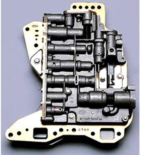
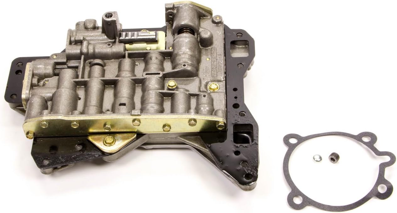
What the C6 valve body actually controls
TransGo's C6 valve body layout names the valves you are dealing with: the throttle modulator valve (TMV), kickdown, throttle boost, low scheduling, cutback, coasting, the 1-2 and 2-3 shift valves, the 2-3 backout valve, the servo regulator and the 1-2 accumulator with its outer, middle and inner springs. The main pressure regulator and the boost valve and sleeve sit at one end, and early 1967-70 units use a different pressure regulator than later ones [5]. Knowing which valve does which job is the whole game, because each one produces a different, recognizable symptom.
- Pressure regulator and boost valve: base line pressure and line rise under load. Wear here affects every range.
- TMV, throttle boost and cutback: turn modulator vacuum into throttle pressure, which sets shift timing and shift firmness.
- 1-2 and 2-3 shift valves: balance governor pressure against throttle pressure to decide when each shift happens.
- 1-2 accumulator: cushions the intermediate band apply on the 1-2.
- Servo regulator and 2-3 backout: time the band release against the reverse-high clutch apply on the 2-3.
- Coasting and downshift valves: closed-throttle 3-1 and forced downshift quality.
Symptoms that point at the valve body
| Symptom | Valve body suspect | Rule out first |
|---|---|---|
| Soft shifts and slow line rise under load; reverse shudder | Worn boost valve sleeve | Modulator, vacuum supply, low fluid |
| Harsh shifts at every throttle position | Pressure regulator spring (wrong or aftermarket) | Disconnected or plugged modulator hose |
| Harsh 1-2, normal 2-3 | Fatigued or missing 1-2 accumulator springs | Vacuum at light throttle |
| 2-3 bind-up or flare | Servo regulator, 2-3 backout valve | Band adjustment |
| Early, late or erratic shift points | Sticking shift valves, TMV or cutback | Governor, kickdown linkage |
| Clunk on 3-1 coastdown | Coasting or downshift valve | Idle speed, closed-throttle pressure |
| Burnt direct clutch or intermediate band on teardown | Boost sleeve wear, accumulator springs | Previous low fluid or overheating |
The two that catch rebuilders most often are the boost valve and the accumulator. Sonnax says C6 transmissions "often display poor line rise," which shows up as erratic shift timing, reverse shudder or direct clutch failure, and traces it to wear on the inside diameter of the boost sleeve that lets oil leak past the boost valve to exhaust [3]. On the older clicker-style valve body with the screw-on boost end plate, Sonnax describes oil entering the modulated line pressure orifice and leaking out through the reverse orifice, with the outside of the sleeve able to leak into the casting as well [4]. The result is the same either way: the pressure never climbs the way it should when you get into the throttle, so the clutches slip right when they are carrying the most torque.
The accumulator side is simpler. Sonnax ties poor 1-2 quality and burnt intermediate bands to fatigue and failure of the 1-2 accumulator valve springs [6]. TransGo's instructions show how much that spring stack matters: all three springs gives a short, smooth 1-2, outer and middle gives shorter and firmer, and outer only is firm [5]. A unit that has lost a spring, or had one pulled by a previous "shift kit" job, shifts noticeably harder on the 1-2 than on the 2-3.
Rule out the outside problems first
A C6 valve body only works with the signals it receives. Before you drop the pan, do the checks that cost nothing.
- Fluid level and condition. Check it hot. Low fluid gives slips and flares that look exactly like line-rise problems. Burnt, varnished fluid is a clue that valves may be sticking. Our C6 fluid type and capacity guide covers the Type F vs MERCON V question.
- Idle speed. Ford's diagnosis form records engine idle rpm right after fluid level [1]. A fast idle causes harsh engagements that no valve body change will fix.
- Vacuum signal. With the engine idling, pull the hose at the modulator. TransGo says the engine must speed up or idle rough; if it does not, the hose is on the wrong port or plugged with carbon [5]. No vacuum means maximum pressure all the time, which feels like a bad regulator valve.
- Modulator. ATF in the vacuum side means a ruptured diaphragm. A modulator that will not hold vacuum on a hand pump has to be replaced.
- Kickdown linkage and band. TransGo's kickdown setting on gas engines is adjusted so you can just get a 3-1 kickdown at 30 mph, and the band is snugged until the driveshaft will not turn backwards, then loosened until it just turns and backed off another 1/4 turn [5]. A tight band causes 2-3 bind-up that gets blamed on the valve body.
Testing in the truck: the pressure test
The pressure gauge is the only way to separate a valve body problem from a clutch problem without taking the unit apart. Ford's procedure records control pressure in each range at above 18 in. Hg, at 10 in. Hg and at closed throttle, using a hand vacuum pump on the modulator to simulate load [1]. Use the chart for your year and engine, because gas and diesel specs are different.
- Normal at high vacuum, fails to rise as vacuum drops: boost valve and sleeve wear, or a weak modulator. This is the classic C6 line-rise failure.
- Low in every range: pressure regulator, pump, or a leak common to all circuits. Sonnax lists low base line pressure and low pump volume among C6 symptoms [2].
- Low in one range only: a leak in that range's circuit, usually a seal or ring rather than the valve body.
- High in every range at idle: no vacuum signal or a heavy pressure regulator spring. Sonnax sells a regulator spring calibrated to OE gas line pressure and lists high line pressure as a C6 symptom [2].
If pressure is correct in every range and the shift is still wrong, the problem is shift timing or cushion: the shift valves, the accumulator, the servo regulator or the governor. On diesels, TransGo adds a hard limit: at maximum throttle in D at 28 mph, line pressure must not exceed 138 psi, and a gas governor installed in a diesel unit will prevent a wide-open-throttle 1-2 [5].
Testing on the bench: inspection and vacuum testing
Once the valve body is out, clean and dry it completely before you judge anything. Sonnax's inspection guide gives the numbers that matter. Total diametrical valve-to-bore clearance for OE spools runs .0005 in. minimum to .0016 in. maximum, which is thinner than a human hair [7]. Contamination bigger than that gap embeds and scores the bore.
Visual check
Pull each valve and look into the bore from the side the fluid enters. Sonnax describes a worn bore as a polished crescent on the loaded side; a flower-petal pattern, a visible step or spiral machining marks also mean the spool no longer seals [7]. Roll each valve on a flat surface and spin it in its bore. If it binds while rotating, it is bent. Check the lands for sharp, burred edges.
Vacuum testing
Vacuum testing is how shops put a number on bore wear. A test nozzle seals a port on one valve's circuit and pulls air through the clearance between the spool and bore, so a tighter fit holds more vacuum. Sonnax says vacuum loss is directly proportional to the wear, that boost valves should always be checked because throttle pressure changes keep them constantly moving in their sleeves, and that regulating valves wear exactly where sealing matters most [8]. That makes the C6 boost sleeve and main pressure regulator the first two places to test.
Sonnax's typical results for a calibrated stand [7]:
- Valves over .450 in. diameter: 17 in. Hg or better.
- Spools under .450 in.: 18 in. Hg or better is suggested.
- 15-17 in. Hg is questionable on how long it will keep working.
- 15 in. Hg or less will not function properly at operating temperature.
Calibrate first. Sonnax's standard is 28 in. Hg within three seconds with the hose sealed, zero with the hose open, and 5-7 in. Hg through a .035 in. orifice [7]. Their boost valve kit pages spell out the replacement rule: install the kit if vacuum testing at the indicated ports fails to hold the recommended minimum, or if wear is visible [3].
No vacuum stand? A wet air test with regulated 30-60 psi air and ATF will show gross leakage, but Sonnax points out it is not measurable and depends on the operator's experience [7].
Repair or replace?
If only the boost sleeve fails, a drop-in kit is the right fix. Sonnax offers gas-ratio kits (36946-01K O-ring style, 36946-04K factory style, 36941-01K for 1976 and earlier clicker units) and diesel-ratio kits (36946-02K and 36946-03K), with the diesel ratio recommended for heavy-duty use. Note the warning: the kit does not recalibrate shift timing or allow a gas valve body to be used in a diesel [3]. TransGo's conversion for that requires a .410 or .437 boost valve and other changes [5].
If several bores fail, the accumulator springs are unknown, or someone has drilled plates without notes, replacement usually wins on labor alone. Whichever you choose, reassemble with a new gasket, leave the plate bolts loose until the valve body halves are tight, and torque to TransGo's 25-35 or 40-50 in-lb specs depending on bolt [5]. Make sure the pan bottom does not press against the filter opening. For the full service, see our C6 filter and pan service guide.
Shop the part for this fix: C6 valve body
Failed the vacuum test in more than one bore? CoreTransmissionParts stocks a complete C6 valve body for 1966-1996 units, ready to bolt in.
View the C6 valve body at CoreTransmissionPartsRebuilding your own? Grab the 1967-1996 C6 valve body gasket (D6AZ-7D100-A).
Need parts for this job?
Our parts shop carries aftermarket and TCI C6 valve bodies, plus Type F and MERCON V for the refill, all on our own checkout. For every Ford fluid spec side by side, see our transmission fluid spec chart.
FAQ
What are the symptoms of a bad C6 valve body?
Soft or slipping shifts under load, reverse shudder, a harsh 1-2 with a normal 2-3, early or late shift points, 2-3 bind-up and a clunk on the 3-1 coastdown. A worn boost valve sleeve that prevents line rise is the most common C6 valve body wear point.
How do you test a C6 valve body?
Start with a pressure test in each range at high vacuum, 10 in. Hg and closed throttle. If pressure fails to rise as vacuum drops, suspect the boost valve. On the bench, inspect each bore for polished crescents and vacuum test the boost and pressure regulator bores; below about 15 in. Hg the valve will not work properly hot.
Can a bad modulator mimic a bad valve body?
Yes. No vacuum signal gives maximum pressure and harsh shifts, and a weak modulator gives soft shifts and poor line rise. Check the hose at idle and test the modulator with a hand pump before you pull the valve body.
Can I use a gas C6 valve body on a diesel?
Not as-is. Sonnax warns its boost valve kits do not allow gas and diesel interchange, and TransGo's conversion requires a .410 or .437 boost valve plus spring changes. The diesel governor must also be correct.
Related guides
Sources
- Ford Motor Company, The C6 Automatic Transmission, technician training book (Forel Publishing reprint, sample pages), including the Automatic Transmission Diagnosis Guide FD-1863-AT. Backs the band, clutch and one-way clutch layout, modulator and governor control, idle rpm on the diagnosis form, and the control pressure test by range at above 18 in., 10 in. and closed-throttle vacuum. forelpublishing.com (PDF)
- Sonnax, Ford C6 unit page. Backs the C6 symptom list (low base line pressure, high line pressure, low pump volume, low line rise) and the regulator spring calibrated to OE gas line pressure. sonnax.com
- Sonnax, C6 Boost Valve Kit 36946-04K. Backs poor line rise, erratic shift timing, reverse shudder and direct clutch failure from boost sleeve wear, the gas and diesel ratio kit list, the no-interchange warning and the vacuum-test replacement rule. sonnax.com
- Sonnax, C6 Boost Valve Kit 36941-01K (1976 and earlier clicker-style). Backs the leak path from the modulated line pressure orifice to the reverse orifice and leakage around the sleeve outside diameter. sonnax.com
- TransGo, SK C6 Shift Kit installation instructions (2011). Backs the valve body layout, 1-2 accumulator spring selection, early and late pressure regulators, the gas vacuum check, the diesel 138 psi limit and governor note, the kickdown and band adjustments, the gas-to-diesel boost valve sizes and the bolt torques. TransGo SK C6 instructions (PDF)
- Sonnax, C6 1-2 Accumulator Valve Spring Kit 36946-05K. Backs poor 1-2 quality and burnt intermediate bands from fatigued accumulator springs. sonnax.com
- Sonnax (Bob Warnke), Valve Body Inspection and Reaming for Repair. Backs the .0005-.0016 in. valve-to-bore clearance, the worn-bore appearance, the bent-valve spin test, the vacuum stand calibration standard, the typical vacuum pass/fail readings and the wet air test limits. sonnax.com
- Sonnax, Vacuum Testing for Leakage. Backs how vacuum testing works, vacuum loss being proportional to wear, and checking boost and regulating valves first. sonnax.com