On a 4L60E you plug in a scan tool and argue with the data. On a Turbo 350 there is no data: no pressure transducer, no PID, no code, no connector. The only instrument that tells you what the hydraulics are doing is a mechanical gauge on the line pressure tap, and without the factory numbers the gauge tells you nothing either. Below is the actual GM chart for this unit, out of a factory service book rather than somebody's memory, plus the procedure that produces numbers worth comparing against it.
What line pressure is on this unit, and what sets it
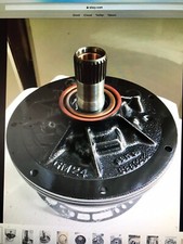
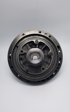
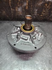
The TH350 runs a fixed-displacement gear-and-crescent pump driven off the converter hub. It moves whatever volume engine speed gives it and cannot change its own displacement, so everything downstream is regulation, not production. The pressure regulator valve dumps the excess back to suction, and where it sits in its bore is what you read on a gauge.
The PR valve does not decide that alone; it gets help from the boost valve. Sonnax describes the division of labor cleanly: the pressure regulator spring sets base line pressure, and the boost valve's job is to help that spring increase line pressure as needed. Oil pressure from the EPC solenoid, vacuum modulator or TV valve is directed to the end of the boost valve, and as that oil pressure changes, so does the force assisting the spring.
On a TH350 that signal comes from the vacuum modulator. GM's description is worth memorizing: the modulator consists of a diaphragm and one spring, the external spring acts on the modulator valve to increase modulator pressure, and engine vacuum acts in the opposite direction to decrease it. Low vacuum, high modulator pressure. High vacuum, low modulator pressure.
So the control logic is a chain: manifold vacuum is the load signal, the modulator converts it to a hydraulic signal, the boost valve turns that into line pressure, and line pressure holds the clutches and bands. When any link is off, the gauge sees it. That is why pressure testing a TH350 is genuinely diagnostic and not a formality.
The factory numbers
These are GM's own specifications from the 1976 Chevrolet Light Truck Service and Overhaul Supplement (ST-330-76), for the TH350 behind the 350 V-8. Both tests are run with the vehicle stationary and the service brake applied.
| Condition | Drive | L1 or L2 | Reverse |
|---|---|---|---|
| Modulator tube disconnected, 1200 rpm | 167 psi | 166 psi | 254 psi |
| Modulator tube connected, engine speed set to hold 12 in. Hg absolute manifold pressure | 85 psi | 105 psi | 129 psi |
Two things about that second row trip people up. First, GM specifies absolute manifold pressure, not vacuum, and your vacuum gauge reads the other direction. At sea level, 12 in. Hg absolute is roughly 18 in. Hg of vacuum on a normal gauge, and it shifts with altitude because the reference is a hard vacuum rather than local atmosphere. Set 12 in. Hg on a vacuum gauge instead and you are testing at a much heavier simulated load than GM intended.
Second, note the scope: this is the 350 V-8 calibration in a 1976 light truck. A six-cylinder car unit, a 305, a different model year or a different modulator part number can all carry different figures. The shape of the chart is the same everywhere, but the values are not universal. Treat the table above as the reference point for a small-block TH350.
What the chart really encodes is the rise. Disconnecting the modulator removes the vacuum signal, which the modulator spring reads as maximum load, driving the boost valve to its maximum position. Drive goes from 85 to 167 psi. Reverse goes from 129 to 254. That near-doubling is the test. A unit that reads plausibly at idle but will not rise has a control problem, not a pump problem, and those get misdiagnosed as worn-out transmissions every day.
Gauge and setup
The line pressure take-off on a TH350 is a pipe-plugged port in the case on the passenger side, up near the vacuum modulator, threaded 1/8 in. NPT. Pull the plug, thread in your adapter, and run the hose out from under the truck.
Gauge selection is not a detail. Jeff Parlee of the Sonnax TASC Force, writing in Transmission Digest, puts the first rule plainly: always use a gauge rated for more pressure than the maximum you expect to see. Here you will command 254 psi in reverse on purpose, so a 300 psi gauge is pinned at the top of its scale exactly when you need it accurate. A 400 or 500 psi gauge is the right tool.
The rest of Parlee's setup rules are the ones that keep this from turning into a bad afternoon:
- Measure during a road test where possible, not on the lift. There is no way to load the transmission on a lift the way road conditions do.
- Keep the gauge out of the cabin. Tape it to the windshield or have a helper hold it outside; it is easier to wash the outside of a truck than the inside.
- Route the hose away from exhaust, driveshafts, axles, fan blades and linkage.
- If the hood must be ajar, tie it down and carry side cutters.
One more specific to this unit: verify the shift linkage before you believe any reading. GM's caution in the linkage adjustment procedure is that inaccuracies there cause operation without the controls in full detent, and that such operation results in reduced oil pressure and partial engagement of the affected clutch. A misadjusted column linkage hands you a low reading on a healthy transmission. Check fluid level hot and running for the same reason: a pump pulling air through a low sump or a cracked filter neck aerates the fluid and the needle goes soft.
Transmission Line Pressure Test Gauge Kit, 500 PSI
500 psi gauge, 60-inch hose and brass adapters, which covers the 254 psi reverse spec with headroom to spare. The kit fits the 1/8 in. NPT take-off on a TH350 and the common GM and Ford ports.
See the gauge kit →Running the test
- Bring the transmission to operating temperature. Cold fluid is thick and reads high.
- Verify fluid level hot and running, and that the shift linkage reaches full detent in every range.
- Pull the pressure plug, install the adapter and hose clear of heat and rotating parts, and mount the gauge outside the vehicle.
- Chock the wheels and set the service brake. You are about to put the truck in gear at 1200 rpm.
- Connected test: modulator tube on, engine speed set to hold the specified manifold pressure. Record Drive, L1/L2 and Reverse.
- Disconnected test: pull the vacuum tube off the modulator and plug it. Set 1200 rpm and record all three ranges again. Do not linger; you are running maximum pressure against a stalled converter and making heat fast.
- Reconnect the modulator tube, shut down, and compare both rows to spec.
For a pump capability check rather than a control check, Parlee's method applies: check minimum line pressure, then maximum line pressure at a fast idle, creating max-pressure conditions by whatever means the unit provides. On a vacuum-modulated transmission that means disconnecting the vacuum. Once those conditions exist you should see the maximum line pressure for that transmission at a fast idle. If you cannot, the pump or the regulator circuit is the problem.
Reading the result
Low in every range, and it will not rise
Suspect the supply and regulation side: fluid level, a plugged or cracked filter, a worn pump, or a pressure regulator valve worn into its bore. A sagging PR spring belongs on this list too. Sonnax notes that a stronger spring can breathe new life into old transmissions with sagging pressure regulator springs, which is another way of saying the spring is a wear item that quietly lowers your baseline.
Low in reverse specifically
This one has a name on the TH350. Per Sonnax, in GM TH350 and TH350C units the OE boost valve sleeve wears out from the reciprocation of the steel valve inside the aluminum sleeve, and wear in the reverse boost sleeve results in low line pressure, soft 1-2 and 2-3 shifts, and reverse engagement or shudder. Steel cycling against aluminum is a losing material pairing, and it is the most common reason a Turbo 350 reads short on the reverse line while looking acceptable elsewhere.
Normal at idle but no rise when you disconnect the modulator
The control signal is not getting through. Check the modulator, the vacuum tube for cracks and oil, and the modulator valve in the case for sticking. Transmission fluid in the vacuum hose means a ruptured diaphragm and an engine that has been drinking ATF.
To test the modulator without guessing, GM's method is a spring tension comparison using tool J-2466: mount a known-good modulator on one end and the suspect on the other, hold them horizontal, and bring them together under pressure until either sleeve just touches the tool. White means acceptable; if the indicator shifts to blue, or white never appears, replace it. It is a comparison test, so it is only as good as your reference unit.
One circuit low, line pressure fine
That is a leak in that circuit, not a pressure problem. Parlee's threshold is the one to use: you know there is a leak in a clutch circuit if the pressure difference between the clutch circuit and line pressure is more than 10 percent. Some difference is normal, because sealing rings do not seal perfectly, and that normal leakage is what fills the 0 to 10 percent band.
Following it onto the bench
When the truck test points at the valve body, the bench test that confirms it is a vacuum test. Sonnax pioneered the method and the numbers are concrete: a perfect vacuum measures 29.9 in. of mercury, an extremely good circuit might approach 22 or 23 in. Hg, and a severely worn bore can read as low as 8 in. Hg. Vacuum loss is directly proportional to the amount of wear, which makes it a measurement instead of an opinion.
Sonnax also says where to start, and it points straight at this unit's weak spot: boost valves should always be checked, because pressure changes keep them constantly moving in their sleeves. The valves doing the most cycling wear first.
Fixing a low number, and not overcooking it
For a worn reverse boost sleeve, Sonnax kit 35754-01K supplies a redesigned anti-stick sleeve plus a reverse and modulator boost valve and an intermediate boost valve, with a larger boost ratio that raises line pressure and firms the shifts.
If the goal is a general pressure lift rather than a specific repair, understand the two levers first. Sonnax's framing is the clearest I have seen: stronger springs have a linear effect, giving the same increase at both ends of the range, while larger boost valves have a progressive effect that changes the rate of increase. That matters because a spring stiff enough to tighten a wide-open upshift is too much pressure shifting into reverse in the garage, and it adds pump load at idle and can drag the converter clutch through reduced cooler flow.
The 350-LB1 kit is built on that logic, pairing a pressure regulator spring roughly 10 percent stronger than OE with a large-ratio boost assembly. Whatever you install, put the gauge back on afterward. A pressure change you did not measure is a pressure change you do not know.
Torque specs for the reassembly
From the same GM factory supplement, for the TH350:
| Fastener | Torque |
|---|---|
| Oil pan to case | 130 in. lbs. |
| Valve body and support plate | 130 in. lbs. |
| Modulator retainer to case | 130 in. lbs. |
| Oil suction screen | 40 in. lbs. |
| Pump assembly to case | 18-1/2 ft. lbs. |
| Pump cover to pump body | 17 ft. lbs. |
| Extension to case | 25 ft. lbs. |
| Detent valve actuating bracket | 52 in. lbs. |
Note how many of those are inch-pounds. The valve body and the pan both land at 130 in. lbs., under 11 ft. lbs. Grabbing a 3/8 ratchet and pulling until it feels right is how support plates get warped and cross-leaks get built into a fresh valve body, and a warped plate shows up on your next pressure test as a number you cannot explain.
While the pan is off: GM's interval is a pan drain and strainer cleaning every 30,000 miles, dropping to 15,000 for heavy city traffic in hot weather, commercial use, prolonged idling or towing, with roughly 2-1/2 quarts going back in. GM also warns fluid temperature can exceed 350°F, so drain it right after operation but respect what is coming out.
Need parts for this job?
Modulators, boost valve kits, pumps, filters, master rebuild kits and pressure test gear for the Turbo 350, all in one place.
Shop TH350 parts →Also worth having in the box: a 500 psi transmission pressure test gauge kit if you do not already run one.
The short version
Warm it up, verify level and linkage, put a 500 psi gauge on the tap by the modulator, and take two sets of readings: modulator connected at the specified manifold pressure, and disconnected at 1200 rpm. On a small-block TH350 that is roughly 85 psi in Drive and 129 in Reverse connected, rising to 167 and 254 disconnected. Low everywhere points at the pump and PR circuit. Reverse alone short points at the boost sleeve. Nothing rising means the modulator never sent the message. The chart does not diagnose the unit by itself, but it turns a vague complaint into one of three specific circuits, and on a transmission with no electronics to interrogate that is the whole game.
Sources
- General Motors — 1976 Chevrolet Light Truck Service and Overhaul Supplement, ST-330-76, Section 7A (Automatic Transmission). Backs the TH350 oil pressure check specifications (167 psi drive, 166 psi L1/L2 and 254 psi reverse at 1200 rpm with the modulator tube disconnected; 85 psi drive, 105 psi L1/L2 and 129 psi reverse with the modulator connected at 12 in. Hg absolute manifold pressure, 350 V-8), the vacuum modulator description of one diaphragm and one spring with vacuum acting opposite the spring, the J-2466 spring tension comparison test and its white/blue indicator result, the shift linkage caution that operation out of full detent reduces oil pressure and partially engages the affected clutch, the TH350 torque specification table, the 30,000 and 15,000 mile pan and strainer service intervals with approximately 2-1/2 quarts on refill, and the warning that fluid temperature can exceed 350°F. Factory manual scan (PDF)
- Transmission Digest — "Diagnosis with Pressure Gauges," Jeff Parlee, Sonnax TASC Force (TASC Force Tips, December 2007). Backs the rule to use a gauge rated above the maximum expected pressure, the instruction to measure during a road test rather than on the lift because the transmission cannot be loaded on a lift as it is on the road, the gauge placement and hose routing safety rules, the pump capability procedure of checking minimum line pressure then maximum line pressure at a fast idle with vacuum disconnected on a modulated unit, and the 10 percent threshold at which a clutch-circuit-to-line pressure difference indicates a leak, with 0 to 10 percent representing normal sealing ring leakage. transmissiondigest.com
- Sonnax — "The Prescription for Optimum Pressure" (September 2010). Backs the explanation that the pressure regulator spring sets base line pressure while the boost valve helps the spring increase it, that the signal at the end of the boost valve comes from the EPC solenoid, vacuum modulator or TV valve, the linear versus progressive distinction between stronger springs and larger boost valves, the warning that a spring increase which tightens loaded upshifts is excessive on a reverse engagement and adds pump load at idle with converter clutch drag from reduced cooler flow, and the point that stronger springs can restore old transmissions with sagging pressure regulator springs. sonnax.com
- Sonnax — Boost Valve Kit 35754-01K (GM TH350, TH350C). Backs the OE boost valve sleeve wearing from reciprocation of the steel valve within the aluminum sleeve, the resulting low line pressure, soft 1-2 and 2-3 shifts and reverse engagement or shudder, and the kit contents of a redesigned anti-stick boost sleeve, reverse and modulator boost valve, and intermediate boost valve with a larger boost ratio. sonnax.com
- Sonnax — Line Pressure Booster Kit 350-LB1 (GM TH350, TH350C). Backs the kit contents of a pressure regulator spring plus a large ratio boost assembly, and the specification that Sonnax pressure regulator springs run approximately 10 percent stronger than OE and are designed for a modest low-end increase with a larger increase under demanding conditions. sonnax.com
- Sonnax — "Vacuum Testing for Leakage" (January 2011). Backs the vacuum test values used here: a perfect vacuum measuring 29.9 in. of mercury, an extremely good circuit reading approaching 22 to 23 in. Hg, a severely worn bore reading as low as 8 in. Hg, vacuum loss being directly proportional to the amount of wear, and the guidance that boost valves should always be checked because pressure changes keep them constantly moving in their sleeves. sonnax.com