A Turbo 400 has no pressure transducer, no line pressure PID and no trouble code to read. GM built this unit from 1964 through the 1990 model year, and outside of a single detent solenoid it decides everything hydraulically, with no computer involved. That leaves one instrument that can tell you what is happening inside it: a mechanical gauge on the line pressure tap. Below are the specifications, the procedure that produces numbers worth comparing against them, and what each reading pattern points at.
What sets line pressure in a TH400
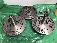
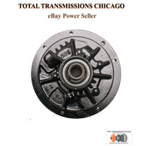
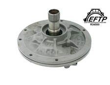
The TH400 pump is a fixed-displacement gear pump driven off the converter hub. It produces volume, not pressure. Pressure exists only because something restricts that volume, and here that something is the pressure regulator valve in the pump cover. Sonnax puts the scale of the job plainly: a hydraulic pump is capable of making tremendous amounts of oil pressure, and the PR valve limits or regulates it down to the 50 to 250 psi range seen in transmissions. Where the valve sits in its bore is a balance of forces, spring and boost valve pushing one way and balance oil pushing back. Once balance pressure is high enough to hold the valve in its regulating position, it starts dumping excess pump volume back toward suction. That balance point is what your gauge reads.
The boost valve is what makes the number move with load. On a TH400 the boost assembly sees two signals: modulated TV oil, generated by the vacuum modulator on the right rear of the case, and reverse oil, which is why reverse carries the higher pressure. Manifold vacuum is the load sensor, the modulator turns it into a hydraulic signal, the boost valve turns that into line pressure, and line pressure holds the clutches and bands.
There is a second job most techs never account for. Sonnax describes the PR valve as a priority valve: it also controls the volume of oil fed to the torque converter, giving priority to line pressure over converter and lube oil. In balance, converter charge and cooler flow are open. Out of balance, that flow is restricted and at times cut off entirely. On a TH400 a line pressure problem and a cooked-converter problem are frequently the same problem.
The factory pressure specifications
These are the THM 400 line pressure specifications published by ATSG in its Techtran manual for the unit. All readings are taken with a gauge installed at the line tap and the service brake applied.
| Range and condition | Normal psi |
|---|---|
| Neutral, brakes applied, 1000 rpm | 55–70 |
| Drive, engine at curb idle | 60–85 |
| Drive, brakes applied, 1000 rpm | 60–90 |
| Drive “2”, brakes applied, 1000 rpm | 135–160 |
| Reverse, brakes applied, 1000 rpm | 95–150 |
| Drive, brakes applied, 1000 rpm, detent solenoid on | 90–110 |
Read the chart as a set of relationships, not six isolated numbers. Neutral is the baseline with almost nothing applied, and Drive at idle sits just above it. Manual “2” is the highest reading because that range boosts line to hold the intermediate clutch and front band. Reverse carries a wide band because reverse oil feeds the boost valve directly. The last row is the one people skip: energizing the detent solenoid should push Drive from the 60 to 90 band up to 90 to 110.
That row is a free electrical and hydraulic test in one. Ground the detent solenoid lead with the gauge connected and pressure should climb roughly 30 psi. If it does not, the cause is a dead solenoid, a blocked detent feed orifice in the spacer plate, a missing detent gasket, or a stuck detent regulator valve, and none of those require pulling the transmission to find.
Where the tap is and what gauge to use
The TH400 line pressure port is a 1/8 in. NPT pipe plug in the case on the driver side, above and slightly behind the manual shift lever, a few inches up from the pan rail. Pull the plug, thread in the adapter, and route the hose out from under the vehicle before starting the engine.
Gauge selection matters more here than on a modern unit. Jeff Parlee of the Sonnax TASC Force, writing in Transmission Digest, states the rule first: always use a gauge rated for more pressure than the maximum you expect to see. Stock spec tops out at 160 psi in manual “2”, but a unit with a booster kit, a manual valve body or a stuck boost valve can read far past that, and a gauge pinned at the top of its scale tells you nothing. A 300 psi gauge is the working minimum here; 500 psi is the better tool.
The rest of Parlee's setup rules were learned the expensive way:
- Take readings on a road test where possible, not on a lift. There is no way to load the transmission on a lift the way road conditions do.
- Keep the gauge out of the cabin. Tape it to the windshield or have a helper hold it outside.
- Route the hose away from exhaust, driveshafts, axles, fan blades and linkage.
- If the hood has to sit ajar, tie it down and keep side cutters with you.
If the complaint is shift timing rather than holding capacity, that is a governor question needing a second gauge: Parlee recommends 0 to 100 psi there, since a 300 or 400 psi gauge cannot read governor pressures accurately.
GEARWRENCH 3343D Engine and Transmission Oil Pressure Test Kit
Gauge, hose and an adapter set that covers the 1/8 in. NPT take-off on a TH400 plus the common GM and Ford ports.
See the test kit →Running the test
- Bring the transmission to normal operating temperature. Cold fluid is thick and reads high, which hides a marginal pump.
- Check fluid level hot and running. ATSG lists it first under low line pressure for a reason: a pump pulling air through a low sump or a damaged filter intake pipe aerates the oil and softens the needle.
- Confirm the manual linkage reaches full detent in every range before trusting a reading.
- Pull the pressure plug, install the adapter and hose clear of heat and rotating parts, and mount the gauge outside the vehicle.
- Chock the wheels and hold the service brake. You are about to load the converter against a stalled output.
- Record Neutral, Drive, Drive “2” and Reverse at 1000 rpm, plus Drive at curb idle. Keep each loaded reading short; a stalled converter makes heat fast.
- Still in Drive at 1000 rpm, energize the detent solenoid and record again.
- To test pump capability rather than control, use Parlee's method: check minimum line pressure, then maximum line pressure at a fast idle, creating the maximum-pressure condition by whatever means the unit provides. On a vacuum-modulated transmission that means pulling the vacuum line off the modulator. If maximum line pressure does not show up under those conditions, the problem is the pump or the regulator circuit, not the shift controls.
Reading the result
Low across every range
The ATSG cause list for low line pressure is worth working in its published order, because it runs cheap to expensive. Fluid level. Vacuum modulator, including carbon buildup where the vacuum line enters the intake manifold, a bent or wrong modulator, or a modulator valve stuck in the case bore. Filter assembly, intake pipe and O-ring seals. Then the pump: pressure regulator or boost valve stuck, wrong boost valve and sleeve, excessive gear clearance, gear pocket wear, pump cover wear, porosity, or a mispositioned pump-to-case gasket. Internal leaks at the clutch piston seals, the pump and center support sealing rings, and the rear servo and front accumulator close the list.
High across every range
Same manual, opposite complaint, and the first half of that list is not inside the transmission at all: low vacuum from a poor engine tune, leaking vacuum lines, a leaking vacuum accessory or storage tank, then a damaged, bent or wrong modulator, or a stuck modulator valve. Only after those does it reach the pump: stuck pressure regulator or boost valve, wrong boost valve and sleeve, incorrect pressure regulator spring, improper assembly, or a damaged aluminum bore plug. On a unit that came back harsh after somebody else rebuilt it, that incorrect spring is usually the answer.
High and uncontrollable, with slow converter charge and poor reverse
This trio is a specific, well-documented TH400 failure. Sonnax reports that high-mileage TH400 and TH425 units frequently lose line pressure control because of a worn pressure regulator bore: the hardened steel valve continuously oscillates in the cast-iron pump bore and wears it, balance line pressure then leaks past the valve and exhausts to the sump, and the valve can no longer move fully into its lower line pressure position. Sonnax lists the result as high cooler pressure and converter, crankshaft and/or friction element failure — the same priority-valve relationship described earlier, showing up as a parts bill.
The repair is drop-in. Sonnax pressure regulator valve kit 34910-03K carries a solid PTFE seal ring separating the balance line circuit from pump suction to stop the cross leak, plus an O-ringed end plug for proper back pressure on the valve, and it avoids replacing the pump casting. Two limits before ordering: it fits 1971 and later units, and if the OE valve has a through balance hole the Sonnax valve cannot be used.
One circuit low while line pressure looks fine
That is a leak in that circuit, not a pressure problem. Parlee gives the threshold: there is a leak in a clutch circuit when the difference between clutch circuit pressure and line pressure exceeds 10 percent. Some difference is normal because sealing rings never seal perfectly, and that normal leakage fills the 0 to 10 percent band.
Following it onto the bench
When the vehicle test points at the pump, the numbers that settle it are dimensional. Sonnax publishes the TH400 pump specifications with its line pressure booster kit, and excess clearance means low pump volume and low pressure:
| Pump check | Specification |
|---|---|
| Gear pocket clearance | .0007 in. to.0026 in. |
| Outer gear to pump body | .005 in. max |
| Pump housing flatness | .001 in. |
Check gear pocket clearance with a feeler gauge and a straight edge across the pump face, or with Plastigauge and the pump bolted together. Inspect the inside of the crescent, the area between the suction and discharge ports, and the gear tooth tips; Sonnax notes that wear on the inner gear tooth tips or the crescent means low pressure. Then wet air test the pump. Leakage that continues after the boost valve and sleeve are replaced indicates cross leakage between the pump halves, which may be warped; resurface or replace them, or use Loctite 518 gasket eliminator on the feed-to-boost-sleeve circuit.
On reassembly, torque matters to your next pressure reading. Per ATSG: valve body bolts 11 Nm (98 in. lbs.) from the center outward, detent solenoid bolts 10 Nm (89 in. lbs.), pump cover and pump retaining bolts 24 Nm (18 ft. lbs.), center support bolt 30 Nm (22 ft. lbs.), cooler line fittings 38 Nm (28 ft. lbs.). Most of that valve body hardware is inch-pounds, and pulling on it with a 3/8 ratchet is how a fresh valve body gets a built-in cross leak.
Raising pressure without breaking something else
If the plan is more holding capacity rather than a specific repair, understand the two levers first. Sonnax draws the distinction clearly: stronger springs have a linear effect, delivering the same increase at both ends of the range, while larger boost valves are progressive, changing the rate of increase so the rise is small at the low end and much larger at the high end. The warning attached to it is the useful part. A spring increase big enough to tighten loaded upshifts is too much shifting into reverse in the garage, and it adds pump load at idle and reduces cooler flow.
Sonnax line pressure booster kit 400-LB1 is built on that logic, pairing a pressure regulator spring roughly 10 percent stronger than OE with a large-ratio boost assembly. One assembly detail: the OE boost sleeve and valve, pressure regulator spring and horseshoe-shaped shim are discarded, while the OE pressure regulator valve, spring seat and retaining ring are retained. Then put the gauge back on. A pressure change you did not measure is a pressure change you do not know.
Need parts for this job?
Vacuum modulators, boost valve and pressure regulator kits, pumps, filters, master rebuild kits and pressure test gear for the Turbo 400, all in one place.
Shop TH400 parts →One more thing worth keeping in the box for this job: a hand-held vacuum pump tester, so you can put a known vacuum on the modulator and watch the gauge respond instead of guessing at the engine's contribution.
The short version
Warm it up, verify level and linkage, put at least a 300 psi gauge on the tap above the shift lever, and read Neutral, Drive, manual “2” and Reverse at 1000 rpm, then energize the detent solenoid and read Drive again. Low everywhere points at level, modulator, filter and pump. High everywhere points at vacuum and the modulator before you touch the transmission. High and uncontrollable with slow converter charge and a lazy reverse is a worn pressure regulator bore. One circuit more than 10 percent below line is a leak in that circuit. On a transmission with nothing to scan, that turns a vague complaint into one specific circuit.
Sources
- ATSG (Automatic Transmission Service Group) — THM 400 (3L80) Techtran service manual. Backs the line pressure specification table used here (55–70 psi Neutral at 1000 rpm, 60–85 psi Drive at curb idle, 60–90 psi Drive at 1000 rpm, 135–160 psi Drive “2” at 1000 rpm, 95–150 psi Reverse at 1000 rpm and 90–110 psi Drive at 1000 rpm with the detent solenoid on, all with brakes applied), the low line pressure and high line pressure cause lists, the detent circuit faults, and the torque values for the valve body, detent solenoid, pump, center support and cooler line fittings. atsgbookstore.com
- Transmission Digest — “Diagnosis with Pressure Gauges,” Jeff Parlee, Sonnax TASC Force, TASC Force Tips, December 2007. Backs the rule to use a gauge rated above the maximum expected pressure, the instruction to measure during a road test rather than on a lift because the transmission cannot be loaded on a lift the way road conditions load it, the gauge placement and hose routing safety rules, the pump capability procedure of checking minimum then maximum line pressure at a fast idle with the vacuum disconnected on a modulated unit, the 10 percent clutch-circuit-to-line threshold for identifying a leak with 0 to 10 percent representing normal sealing ring leakage, and the guidance to use a 0 to 100 psi gauge for governor pressure because larger gauges are not sensitive enough at those pressures. transmissiondigest.com
- Sonnax — “Anatomy of a Transmission: Oil Flow in the Pump-PR-Converter-Cooler Lube Circuits,” Gregg Nader. Backs the description of the pump as capable of tremendous pressure with the PR valve limiting it to the common 50 to 250 psi range, regulated line pressure being the balance oil pressure required to hold the valve in its regulating position, excess pump volume being routed back to suction, and the PR valve acting as a priority valve that gives line pressure priority over converter and lube oil so that converter charge and cooler flow are restricted or cut off when the valve is out of balance. sonnax.com
- Sonnax — Pressure Regulator Valve Kit 34910-03K (GM TH400, TH425). Backs the worn pressure regulator bore failure: the hardened steel valve oscillating in the cast-iron pump bore, balance line pressure leaking past the valve and exhausting to sump so the valve cannot reach its lower line pressure position, the resulting high cooler pressure and converter, crankshaft and/or friction element failure, the symptoms of high and uncontrollable line pressure with delayed converter charge and poor Reverse engagement, the PTFE seal ring and O-ringed end plug repair, the 1971-and-later fitment, and the caution that the kit cannot be used if the OE valve has a through balance hole. sonnax.com
- Sonnax — Line Pressure Booster Kit 400-LB1 installation instructions (GM TH400), 400-LB1-IN. Backs the TH400 pump specifications used here (gear pocket clearance.0007 in. to.0026 in., outer gear to pump body.005 in. max, pump housing flatness.001 in.), the measurement methods with feeler gauge and straight edge or Plastigauge, the note that wear on the inner gear tooth tips or crescent means low pressure, the wet air test showing cross leakage between pump halves with the Loctite 518 remedy on the feed to boost sleeve circuit, and the assembly detail of discarding the OE boost sleeve and valve, pressure regulator spring and horseshoe-shaped shim while retaining the OE pressure regulator valve, spring seat and retaining ring. Instruction sheet (PDF)
- Sonnax — “The Prescription for Optimum Pressure,” September 2010. Backs the linear versus progressive distinction between stronger pressure regulator springs and larger boost valves, the warning that a spring increase which tightens upshifts under heavy load is too much increase shifting into Reverse in the garage while adding pump load at idle and reducing cooler flow, and the specification that Sonnax pressure regulator springs run approximately 10 percent stronger than OE and are paired with large ratio boost valves in the booster kits. sonnax.com