Most 200-4R lockup complaints land on the bench sounding like three different problems: "it won't lock up on the highway," "it feels like the brakes are dragging when it shifts into second," and "it shudders around 40." They are all the same circuit. The 200-4R's torque converter clutch is about as simple as GM ever built one: one on/off solenoid, one apply valve in the pump, a couple of switches, and the computer deciding when to complete the circuit. Simple does not mean trouble-free. The apply valve bore wears, the switches get swapped during swaps and rebuilds, and the converter pays for it. This is how the system actually works and how to find which piece is lying to you.

How 200-4R lockup works: one solenoid, one valve
Sonnax sorts GM converter clutch circuits into three families by how they are controlled: one on/off enable solenoid, an enable solenoid plus a pulse-width-modulated (PWM) solenoid, or a single PWM solenoid. The 200-4R belongs to the first and oldest family, the same on/off style used in the 700-R4 and early 4L60 before the 4L60-E moved to an enable-plus-PWM circuit (Sonnax, GM TCC Circuits). There is no slip control and no ramp. The clutch is either released or fully applied.
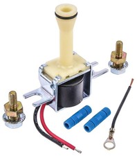
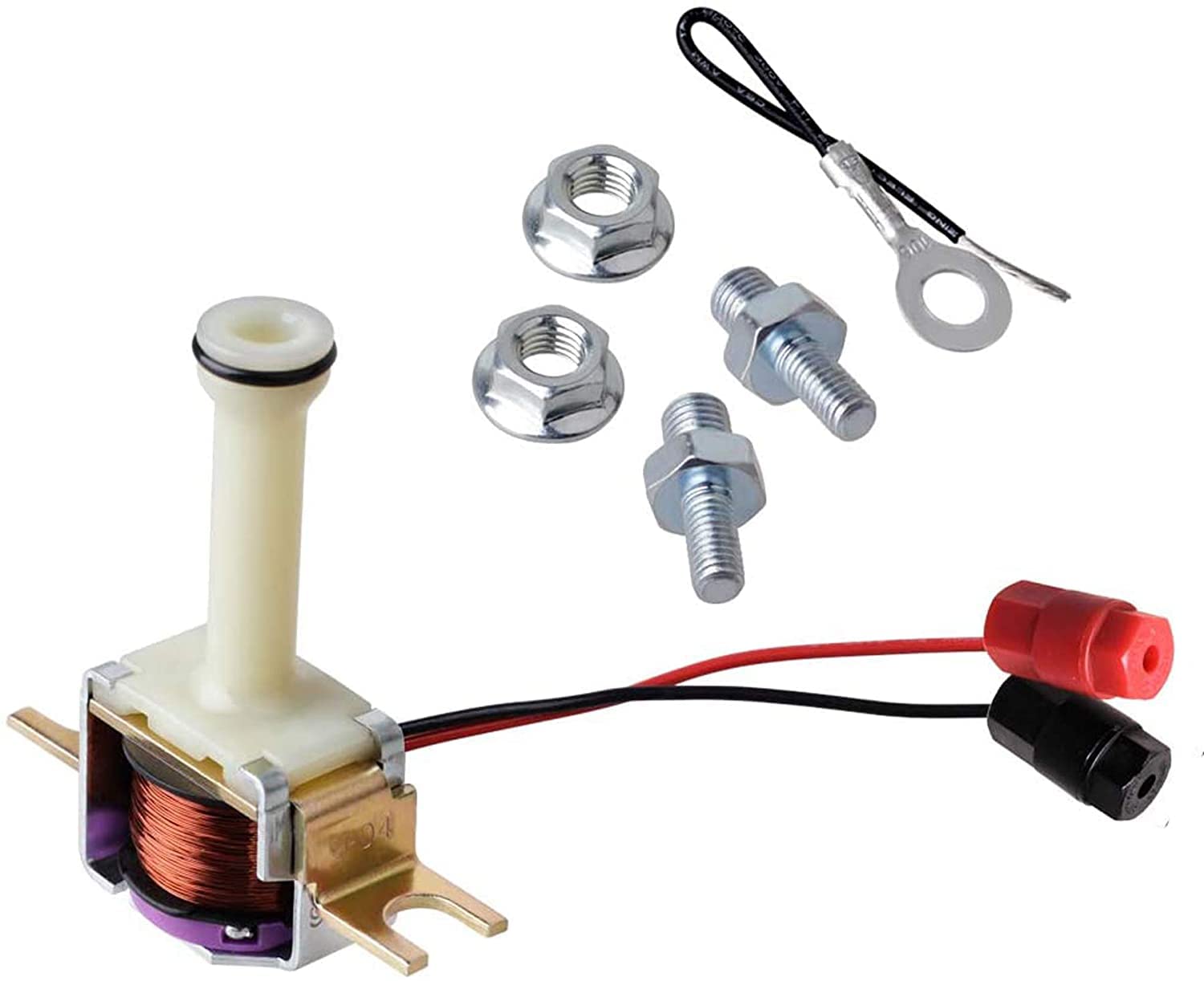
Here is the oil path in plain terms. Converter feed oil normally flows into the release side of the converter, holding the clutch plate off the cover, and returns through the cooler. The TCC apply valve sits in a bore in the pump. Signal oil pushes on one end of that valve. When the solenoid is off, its exhaust is open and signal oil bleeds away, so the spring holds the apply valve in the release position. When the computer energizes the solenoid, the exhaust closes, signal pressure builds, the valve strokes, and converter feed is redirected to the apply side. The clutch locks against the cover and the converter is now a solid coupling.
Because the circuit is on/off, apply feel depends on orificing and the condition of the clutch lining, not on software. That is why a 200-4R lockup feels like a distinct bump, and why it is so sensitive to a valve that leaks.
Who decides when it locks
On factory computer-controlled cars, the solenoid is typically fed switched 12 volts through the brake pedal switch, and the engine computer completes the ground side when its conditions are met: engine warm, vehicle speed above its threshold, steady throttle, and the right gear information from the pressure switches on the valve body. Press the brake and power to the solenoid drops, which is the "brake cancel" that releases lockup when you slow down. Wire colors, switch counts and pin assignments changed by year and car line, so pull the wiring diagram for the exact vehicle before cutting anything. Builders who have pulled many of these report the gear switches are normally closed and open when their gear applies; check yours with an ohmmeter rather than trusting that.
B&M's lockup power switch instructions confirm two details that matter for diagnosis. First, 1981-86 TH200-4R cases have a fourth gear oil pressure tap on the case, which is where B&M installs a pressure switch in series with the wire to terminal "A" of the case connector. Second, B&M states that GM four speeds should always be in lockup in fourth gear because of the increased chance of overheating the converter, and their kit is designed so it cannot cancel fourth gear lockup (B&M 80217 instructions). If a customer has a toggle switch that kills lockup in overdrive, that is a heat problem waiting to happen.
Symptoms and what they point to
| Symptom | Most likely area |
|---|---|
| Never locks up, tach never drops at cruise | No power or no ground at the solenoid, bad solenoid, wrong switch wiring, or apply valve stuck in release |
| Locks cold, falls out of lockup hot | Worn TCC apply valve bore in the pump leaking signal oil |
| Locks up right after the 1-2 shift, feels like dragging brakes | Converter feed leaking into the signal circuit past a worn apply valve bore, or a switch wired so lockup is commanded in second |
| Stalls or bogs coming to a stop, no brake cancel | Apply valve stuck in apply, solenoid exhaust blocked, or brake switch not cutting power |
| Fluid blown out of the dipstick tube | Cross-leakage at the apply valve; Sonnax lists this as a symptom of bore wear |
| Shudder at 35-45 mph in third or fourth | Lockup clutch engagement, fluid condition, or an engine misfire that mimics it |
The last row is worth a pause. A Gears magazine article on shudder diagnosis notes that a shudder between 35 and 45 mph in third or fourth is a strong indicator of lockup clutch engagement, but that secondary ignition failures cause misfires that feel the same and get worse under heavy load at low rpm (Gears, Shudder Diagnosis). On a carbureted or TBI V8 with old plug wires, rule out the ignition before you condemn the converter. The quick check: unplug the TCC connector at the case and road test. If the shudder goes away with lockup disabled, it is in the converter or the lockup hydraulics. If it is still there, look at the engine.
The apply valve bore: the most common hydraulic failure
The TCC apply valve rides directly in the aluminum pump body. After enough miles the bore wears, and Sonnax lays out exactly what happens next. Excessive bore-to-valve clearance lets signal oil leak past the spool, which prevents lockup or makes it drop out when hot. Converter feed oil can also leak past the worn clearance and combine with signal oil, which causes premature lockup. Sonnax describes the result as no lockup, or lockup immediately after second gear once the fluid warms up, and notes that the solenoid frequently has no control over the valve's position (Sonnax 77805-K).
The worst case is the middle case. Sonnax explains that cross-leaks can float the valve into a midway position that restricts cooler flow. The converter is now partly applied, slipping, and not getting cooled, and it burns. If you are replacing a converter on a 200-4R and you do not address the apply valve bore, you are setting up the new converter for the same death.
PWM vs non-PWM: do not mix them
Sonnax's 77805-K kit fits non-PWM units, which covers the 200-4R, and puts a PTFE-sealed steel valve in the worn bore to stop the cross-leak. The same pump family later went PWM in 4L60-E service, and Sonnax warns that mismatching PWM and non-PWM valves causes rapid converter failure. The identification tip: a non-PWM OE valve has double spools at the location Sonnax shows; a single spool means PWM. Sonnax also warns not to identify it by material, because some early PWM pumps used steel valves too. If someone has put a 4L60-E pump on a 200-4R or vice versa, check this first.
Diagnosis on the car, step by step
- Check fluid level and condition hot. Dark, burnt fluid with a varnish smell and lining material in the pan says the converter clutch has already been slipping. GM's current guidance is DEXRON VI for transmissions that originally called for earlier DEXRON fluids (GM Service Insights). Worn-out fluid alone can cause shudder.
- Confirm the road test. Warm the car up fully. At a steady 45-55 mph in fourth, watch the tach. Lockup should drop engine speed by a couple hundred rpm with a light bump. Tap the brake pedal: rpm should rise as it releases.
- Check power at the case connector. Key on, engine off, back-probe the feed terminal. You want battery voltage with the brake released and zero with the brake pressed. No voltage at all means a fuse, brake switch or harness problem, not a transmission problem.
- Check the solenoid. Measure resistance across the solenoid at the case connector, then through the switches. Builders commonly report roughly 25 ohms for these solenoids; compare against the factory spec for your year. Open means a failed coil or broken internal wire. Very low means a shorted coil that can take out the computer's driver.
- Command it manually. With the engine warm, ground the solenoid control wire through a test lamp at cruise where it is safe to do so. If the converter locks when you ground it, the solenoid and hydraulics work and the problem is the computer's decision: switch input, coolant sensor, vehicle speed signal or TPS. If it will not lock when commanded, the problem is inside.
- Inside the pan. B&M's troubleshooting list for "no converter clutch apply" on the 200-4R is a good checklist: voltage not reaching the solenoid, harness plug not fully engaged, connectors on the wrong switches, wires pinched and grounded out, and a stuck converter clutch valve. For "no converter clutch release," B&M lists the apply valve stuck open (B&M 35265 instructions). The internal harness wires get pinched under the valve body more than you would think after a shift kit install.
The fix
Electrical failures
A failed solenoid, a bad internal harness or a switch on the wrong terminal can be fixed with the pan off. When you replace the solenoid, inspect its O-ring and the seat it seals against, and route the internal harness so nothing is trapped under the valve body. Reassemble the valve body to B&M's 11 N·m (8 ft-lb) and torque the pan to 14 N·m (10 ft-lb). Over-tightened valve body bolts distort the bores and can make valves stick, which is the opposite of what you are trying to fix.
Apply valve bore wear
This one is a pump repair. Either ream and install a sealed replacement valve, or use a known-good pump. While the pump is apart, check the pressure regulator bore and the TV boost sleeve, since they wear on the same unit for the same reason. A pump that has worn the TCC bore usually has company.
A slipping or glazed converter
If the lockup lining is already burned, the converter has to be replaced. Flush the cooler and lines, since a burned lining spreads debris through the circuit, and fix whatever caused the slip before the new one goes in. The Gears article makes the point that a small amount of slip while applied is normal on many lockup clutches, but a lining that is slipping enough to shudder is past saving.
Swaps and standalone lockup control
The 200-4R gets swapped into a lot of carbureted cars that never had a lockup computer. Those cars need something to command lockup, and the usual answer is a standalone lockup kit that uses a vacuum switch and the brake switch, or a fourth gear pressure switch, to energize the solenoid. Two rules hold no matter which kit you use: release lockup under hard throttle and on braking, and keep it applied in fourth at cruise. B&M's warning about fourth gear heat is the reason. A 200-4R cruising in overdrive with an unlocked converter generates heat that cooks fluid, seals and the converter itself.
If a swap car locks up in second or third and drags the engine, the switch is usually on the wrong pressure tap or wired so the circuit is complete too early. Recheck which switch and which pin before you blame the transmission.
TCC solenoids, lockup control kits, pumps and rebuild kits for the 200-4R lockup circuit.
Shop 200-4R parts →Shop the part for this fix: Sonnax TCC Apply Valve Kit 77805-K
The sealed, drop-in valve for the worn pump bore that causes hot drop-out, early lockup and burned converters on non-PWM 200-4R pumps. CoreTransmissionParts also carries the 200-4R TCC solenoid and lockup kits.
Shop the apply valve kit at CTP → All 200-4R parts at CTP →FAQ
How do I know if my 200-4R torque converter is locking up?
Warm the car up and hold a steady 45-55 mph in fourth. When lockup applies you feel a light bump and the tach drops by a couple hundred rpm. Tap the brake pedal and the rpm should rise again as lockup releases.
Why does my 200-4R fall out of lockup when it gets hot?
The most common cause is a worn TCC apply valve bore in the pump. Sonnax explains that the extra clearance lets signal oil leak past the valve, so it cannot hold the apply position once the fluid thins out. The repair is a sealed replacement valve or a known-good pump.
Does the 200-4R need a computer to lock up the converter?
Factory cars used the engine computer to ground the solenoid, with power fed through the brake switch. Swapped cars without that computer need a standalone lockup kit that uses a vacuum switch, brake switch or fourth gear pressure switch to energize the solenoid.
Is it okay to disable lockup in overdrive on a 200-4R?
No. B&M states that GM four speeds should always be in lockup in fourth gear because an unlocked converter in overdrive greatly increases the chance of overheating. Disabling lockup in third and below for city driving is fine, but keep it applied in fourth.
What causes a 200-4R to lock up right after the 1-2 shift?
Converter feed oil leaking past a worn apply valve bore can add to signal oil and stroke the valve early, which Sonnax lists as a classic bore-wear symptom. A pressure switch wired to the wrong terminal can also command lockup in second. Check the wiring first, then the pump.
Sources
- Sonnax, "GM TCC Circuits" (Maura Stafford) — GM converter clutch circuits grouped by control method; 700-R4/4L60 on/off style circuit vs the 4L60-E enable plus PWM circuit; early TCC enable solenoid circuits. sonnax.com
- Sonnax, TCC Apply Valve Kit 77805-K (200-4R, 4L60, 4L60-E non-PWM) — pump bore wear causes no lockup, hot drop-out, lockup right after second and fluid out the fill tube; midway valve restricting cooler flow; PWM vs non-PWM identification and mismatch warning. sonnax.com
- B&M Racing & Performance, Power Switch 80217 for GM lockup converters, installation instructions — 1981-86 TH200-4R fourth gear oil pressure tap; switch in series with terminal "A"; GM four speeds should stay in lockup in fourth due to converter overheating. B&M instructions (PDF)
- B&M Racing & Performance, Shift Improver Kit 35265 for THM200-4R, installation instructions — troubleshooting for no converter clutch apply and no release; valve body bolts 11 N-m, pan bolts 14 N-m. B&M instructions (PDF)
- Gears magazine (ATRA), "Shudder Diagnosis" — 35-45 mph shudder in third or fourth points to lockup engagement; misfires mimic converter shudder; some lockup slip is normal; fluid as a shudder cause. gearsmagazine.com
- GM Service Insights, "Use the Right Transmission Fluid" — DEXRON VI for GM transmissions that specify earlier DEXRON fluids. gmserviceinsights.com