Every few months somebody rolls a 4L60E into the shop convinced the modulator is bad. They have been under the truck with a flashlight looking for the vacuum line, they cannot find it, and they want to know if GM hid it behind the exhaust. That is a fair question if your last GM automatic was a TH350. It just does not have an answer, because there is no modulator on a 4L60E, there is no vacuum hose going to the case, and there is nothing on the outside of the unit you can turn to change shift pressure.
What replaced it is more interesting than the myth. GM did not delete throttle pressure. It kept the exact same hydraulic job and handed it to a solenoid. Understanding that swap is the difference between chasing a part that does not exist and diagnosing the circuit that actually sets line pressure.
The short version: A vacuum modulator and a TV cable both do one thing — create a variable pressure that pushes on the boost valve so line pressure rises with engine load. In a 4L60E that pressure is called torque signal fluid, and it is created by the pressure control solenoid (PCS), also called the EPC solenoid. Per Sonnax, "oil pressure from the EPC solenoid, vacuum modulator or TV valve is directed to the end of the boost valve" — three different front ends feeding one identical hydraulic circuit. Nothing about that circuit is adjustable from outside the transmission.
What a Vacuum Modulator Actually Did
A modulator is a can with a diaphragm, a heavy spring and a pin. Manifold vacuum on one side of the diaphragm fights the spring on the other. As Steve Garrett laid it out in ATRA's Gears Magazine, when load increased, manifold vacuum dropped, and the modulator pushed its valve further into the bore, raising throttle pressure. High vacuum at light throttle meant low throttle pressure and soft, early shifts. Low vacuum at wide open throttle meant high throttle pressure, firm shifts and high line pressure.
It worked because manifold vacuum is a usable stand-in for engine load. It was also crude for exactly the same reason: vacuum is not torque. A cam swap, an intake leak, a collapsed hose, elevation, or a forced-induction engine all lie to the modulator. And the failure modes were ugly. A torn diaphragm draws ATF straight into the intake, and a restricted or cracked vacuum line quietly moves every shift point in the transmission with no code and no warning light.
The 700R4 and 4L60 went a different direction with a mechanical TV cable, which was more accurate but far less forgiving. Garrett notes each click of TV cable adjustment amounts to roughly 10 psi of line pressure, and getting it wrong is a known path to 3-4 clutch failure. If you want that comparison in depth, we covered it in electronic TV versus the 700R4 cable.
The one "modulator" that does live in a 4L60E
There is a valve in a 4L60E that carries the word. The actuator feed limit (AFL) valve is called a solenoid modulator or a solenoid regulator valve depending on the manufacturer, and it is a spool in the valve body, not a vacuum can. It takes line pressure and regulates it down to roughly 115 psi to feed the shift solenoids, the pressure control solenoid, the TCC solenoid, the 3-2 control solenoid and the 2-3 shift valve train. It matters, and its bore wears — see our AFL valve writeup — but it has nothing to do with engine vacuum.
What GM Put in Its Place: Torque Signal Fluid
Open the GM Hydra-Matic 4L60-E Technician's Guide to the pump section and the language is unambiguous. The pressure regulator valve is biased by torque signal fluid pressure, pressure regulator spring force, line pressure acting on the end of the valve, and reverse input fluid acting on the boost valve in Reverse. Torque signal fluid moves the boost valve against the isolator spring, and the isolator spring passes that force to the pressure regulator valve. Line pressure increases as throttle position and engine torque increase.
Substitute "modulator pressure" for "torque signal fluid" in those sentences and you have described a TH350 pump. The valve train did not change conceptually. Only the source of the signal did.
So where does torque signal fluid come from? The PCS regulates AFL fluid into the torque signal circuit. Torque signal fluid is then routed, in every gear range, to two places: the boost valve and the accumulator valve. That second destination is the one people forget. The same solenoid that sets line pressure also sets accumulator back pressure, which is why a pressure problem in a 4L60E shows up as shift feel as much as holding capacity.
One more thing the modulator crowd will not recognize: the 4L60E pump is a variable displacement vane pump. Excess line pressure at the regulator valve is fed into the decrease circuit, which routes back to the pump slide and changes how much the pump puts out. Line pressure here is not merely regulated, it is produced to demand.
The Numbers, and Why They Run Backwards
Per the GM technician's guide, the PCS is a precision electronic pressure regulator that the PCM operates at approximately 292.5 Hz on a positive duty cycle, meaning the PCM controls the high side and permanently supplies the ground. What throws people is the direction of the relationship:
| Condition | PCS duty cycle | PCS current | Torque signal | Line pressure |
|---|---|---|---|---|
| Minimum throttle (idle) | approx. 40% (maximum) | approaches 1.0 amp | Minimum | Minimum |
| Part throttle | varies 40% to 0% | varies 1.0 to 0.0 amp | Rising | Rising |
| Wide open throttle | approx. 0% (de-energized) | approaches 0.0 amp | Maximum | Maximum |
| Electrical system disabled | 0% | 0.0 amp | Maximum | Maximum |
More current equals less pressure. GM's own control-pressure curve for the solenoid runs from 0.0 to 1.1 amp of input current against 0 to 100 psi of control pressure, sloping down to the right. Mechanically, current pulls the armature toward the push rod and opens a variable bleed exhaust, which dumps AFL fluid and lets spool valve spring force close off the torque signal feed. Cut the current and the bleed closes, the spool opens, and torque signal pressure goes to maximum.
That last row of the table is worth internalizing before you touch anything. In fail-safe mode the PCS goes off, and GM's stated reason is to drive line pressure to maximum so nothing slips until the fault is corrected. It is also why a 4L60E with the case connector unplugged bangs into gear on the lift. That is the system working as designed, not a broken solenoid. The pressure relief ball and spring in the pump keep the whole thing from running away, preventing line pressure from exceeding roughly 2240 to 2520 kPa, or 320 to 360 psi.
Why GM Bothered
GM's own service literature answers this directly. In the Hydra-Matic 4L60-E general information section, GM points out that when you use springs and hydraulic pressure to control line pressure, the control is purely linear, and a straight line is a poor match to an engine torque curve that is anything but. Electronic control over line pressure allows a much closer match to engine output, so shift feel tracks what the engine is actually making.
Then there is the part a modulator could never do. The PCM processes sensor data roughly every 25 milliseconds and continually monitors 1-2 upshift duration against its programmed limits. As friction material and spring tension wear, that shift time drifts, and the PCM modifies line pressure through the PCS to pull it back. GM specifies the adaptive range: line pressure can be adapted from 35 kPa below to 70 kPa above normal line pressure, roughly 5 psi under to 10 psi over. A transmission that trims its own apply pressure as it wears was never going to come out of a vacuum can.
What This Changes About Diagnosis
There is no screw and no cable, so pressure diagnosis moves to the scan tool and the gauge. Three practical consequences:
The load signal now comes from the engine controller. If the engine's calculated torque is wrong, shift pressure is wrong, and the transmission will not set a code for it. Wayne Colonna documented the textbook case in Transmission Digest: harsh engagements and harsh shifts, scan data showing no amperage command to the EPC solenoid and line pressure therefore at maximum, no transmission codes stored but lean codes in the ECM, and often ABS or stability control lights on as well. It shows up on 5.3L non-flex-fuel Silverados, and the cause is frequently ethanol-blend fuel in a vehicle not built for it. The repair is fuel, not a valve body.
Do not trust the commanded PID by itself. The scan tool will happily report the amperage the PCM intended to send. Put a current clamp on the PCS feed and confirm what the solenoid is actually getting. A PCM with a failed driver reports a healthy command all day long.
Sweep it, do not sample it. With bidirectional control, command desired PCS current in 0.1 amp steps and watch a mechanical gauge on the line tap. Pressure should climb steadily as commanded current falls. A curve that flattens at the top, or that will not reach spec at 0.0 amp, is a hydraulic problem and not an electrical one. Our 4L60E line pressure testing walkthrough has the full procedure and the gauge rules that keep the test honest.
The Wear Item the Modulator Crowd Never Had
Electronic control brought its own failure. Because the PCS is pulsing hundreds of times per second, the torque signal circuit downstream of it never sits still, and the parts it acts on pay for that. Sonnax states it plainly: the duty cycle of the EPC solenoid causes the boost sleeve to wear quickly. Oil entering the torque signal orifice then leaks past the boost valve and exhausts at the Reverse orifice, and the outside diameter of the sleeve leaks through the pump body as well. The result is poor line rise, and the symptoms Sonnax lists for it are 3-4 clutch failure, 2-4 band failure, low line rise and poor shift quality.
Read that again in the context of the myth. A guy comes in certain the modulator is bad because his shifts went soft and his 3-4 clutch burned. He is not wrong about the symptom, and he is not even wrong about the circuit. He is wrong about which end of it. The signal is fine; the valve the signal pushes on is leaking.
Two things to know before you order parts, because the pump changed over the years:
- Sleeve length. Early-style pumps use a 1.907" long sleeve; late-style pumps use a 1.809" short sleeve. Sonnax warns the transmission will not function properly if the wrong length sleeve is installed, so measure the OE sleeve before you pick a kit.
- Spool diameter. OE EPC spool diameters run.421",.470" and.472" depending on style, with a.490" available as an increased-ratio upgrade over the.470". Diameter is the boost ratio, so this choice changes how hard pressure rises, not just whether the bore leaks.
GM changed it too. For MY2003, GM released a new-design pressure control solenoid with a new terminal connection, which also forced a change to the internal wiring harness, and it altered line pressure enough that GM published a revised pressure-check procedure to go with it. At the same time GM reduced the orifice in the boost valve sleeve from a nominal 1.08 mm to 0.89 mm, gave the bushing a new part number, and marked it with yellow dye. If you are mixing pump parts across years, that yellow dye is telling you something. More on the pump side in our pressure regulator and boost valve wear writeup.
If You Are Swapping One In
Coming from a TH350, TH400 or 700R4 into a 4L60E, three rules save a lot of grief. There is no vacuum port to connect, so cap the manifold fitting and forget it. There is no TV cable bracket, and no, you cannot rig one — the throttle input reaches this transmission electrically or not at all, which means a factory PCM or a standalone controller is mandatory rather than optional. And resist the old trick of wiring a resistor into the PCS circuit to raise pressure. The PCM watches shift times and adapts, so it will spend the next few hundred miles undoing your resistor. If you want more line pressure in a 4L60E, do it hydraulically with a pressure regulator spring and a larger-ratio boost valve. Sonnax's booster kits use springs roughly 10 percent stronger than OE paired with a large-ratio boost valve, which gives a small increase at idle and a much larger increase under load instead of a flat bump everywhere.
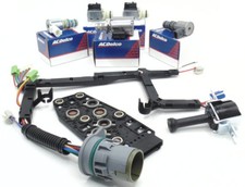
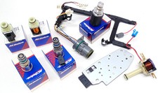
4L60E EPC Pressure Control Solenoid, 1992-2002
If your sweep test says the solenoid is the problem and not the pump, this is the part. Direct replacement for the early-style PCS in 1992-2002 units. For a solenoid job you already have the pan down for, the master EPC solenoid kit for 1993-2002 bundles it with the filter and gaskets. Both from our sister store CoreTransmissionParts, or browse the full 4L60E parts collection.
Shop the EPC pressure control solenoid →Shop 4L60E EPC and shift solenoids, solenoid and filter service kits, pump and accumulator parts, shift kits and full rebuild kits — shipped fast from the USA.
Shop 4L60E parts →Sources
- General Motors Powertrain — Hydra-Matic 4L60-E Technician's Guide (PDF). Backs the pressure control solenoid operating at approximately 292.5 Hz on a positive duty cycle, the PCS regulating AFL fluid into torque signal fluid, the roughly 40 percent / 1.0 amp minimum-throttle and 0 percent / 0.0 amp wide-open-throttle values, the 0.0 to 1.1 amp versus 0 to 100 psi control pressure curve, fail-safe driving line pressure to maximum, torque signal fluid routed to the boost valve and accumulator valve, the variable displacement vane pump and decrease circuit, and the pressure relief ball limit of 2240 to 2520 kPa (320 to 360 psi). 4L60-E Technician's Guide (PDF)
- General Motors service information — Section 7C1, Hydra-Matic 4L60-E Automatic Transmission: General Information (VY Series, PDF). Backs the statement that spring-and-hydraulic line pressure control is purely linear and a poor match to engine output, the PCM processing sensor data every 25 milliseconds, adaptive line pressure ranging from 35 kPa below to 70 kPa above normal based on 1-2 upshift time, the MY2003 pressure control solenoid redesign and harness change, and the boost valve sleeve orifice reduction from a nominal 1.08 mm to 0.89 mm with yellow dye identification. GM Section 7C1 (PDF)
- Sonnax — The Prescription for Optimum Pressure. Backs the statement that oil pressure from the EPC solenoid, vacuum modulator or TV valve is directed to the end of the boost valve, the pressure regulator spring setting base line pressure, the reverse reaction area on the boost valve, and the roughly 10 percent stronger-than-OE spring paired with a large-ratio boost valve for a progressive rather than linear increase. sonnax.com/tech_resources/100
- Sonnax — Boost Valve Kit 77898E-K. Backs the EPC solenoid duty cycle wearing the boost sleeve quickly, torque signal oil leaking past the boost valve and exhausting at the Reverse orifice, sleeve OD leakage through the pump body, the listed symptoms of 3-4 clutch failure, 2-4 band failure, low line rise and poor shift quality, and the sleeve length and EPC spool diameter chart (1.907" early and 1.809" late sleeves;.421",.470" and.472" OE spools with a.490" increased-ratio upgrade). sonnax.com/parts/2484
- Transmission Digest — Wayne Colonna, Avoiding 4L60-E harsh shifts and engagements (July 2022). Backs the case of harsh engagements and shifts with no amperage command to the EPC solenoid and line pressure at maximum, no transmission codes but lean codes stored in the ECM, ABS or stability control lights illuminated, prevalence on 5.3L non-flex-fuel Silverados, and ethanol-based fuel as a root cause. transmissiondigest.com
- Sonnax, published in Transmission Digest — Hydraulic Fundamentals: AFL/Solenoid Modulator Valves (April 2020). Backs the AFL valve also being called a solenoid modulator or solenoid regulator valve, and line pressure being regulated at approximately 115 psi in the GM 4L60-E and 4L80-E to feed the shift solenoids, pressure control solenoid, TCC solenoid, 3-2 control solenoid and 2-3 shift valve lineup. transmissiondigest.com/tasc-force-tips-3
- Gears Magazine (ATRA) — Steve Garrett, A Blast From The Past: Old School Transmissions and Other Forgotten Information (October 2024). Backs the vacuum modulator mechanism, with falling manifold vacuum under load pushing the valve further into the bore to raise throttle pressure, the common failure modes of sticking throttle valves, restricted vacuum lines and misadjusted cables, and roughly 10 psi of line pressure per click of TV cable adjustment with 3-4 clutch failure as the consequence of getting it wrong. gearsmagazine.com