The 4L60E went through one change to its torque converter clutch that trips up more people than almost anything else on the unit: partway through its life, GM switched the way it locks up the converter. Early transmissions apply the clutch like a light switch — fully on or fully off. Later ones ease it in with a pulse-width-modulated (PWM) solenoid so the converter can partially slip under control. The two systems use different solenoids, different valve bodies, different pumps, and different wiring, and they do not mix. If you buy the wrong solenoid, feed a PWM valve body with an on/off signal, or drop a non-PWM pump into a late unit, you get shudder, codes, or no lock-up at all.
This is the plain-English version of what actually changed, how to tell which system you have, how the wiring differs, and what the common lock-up codes are really telling you.
The short version: 1993–1995 4L60E units use a simple on/off TCC solenoid — the converter clutch is either applied or released. From 1996 on, GM went to a PWM TCC solenoid that varies its duty cycle to ramp apply pressure and hold a small, controlled amount of converter slip (EC3 strategy). The two use different pump valve trains and different electrical control, so the parts are not interchangeable. Match the part to the year, not to what physically fits the case.
What the TCC Does, and Why GM Changed It
The torque converter clutch (TCC) is a friction clutch inside the converter that mechanically links the engine to the transmission input once you are up to speed. Locked up, it kills the fluid-coupling slip that a converter normally has, which improves fuel economy and drops converter heat on the highway. The question is only how you apply that clutch.
On the early 4L60E, the answer was blunt. When the PCM decided lock-up was appropriate, it energized the TCC solenoid, which stroked the converter clutch (TCC apply) valve. That valve exhausted the converter release fluid and opened the apply circuit, slamming the clutch on. De-energize the solenoid, the valve returns to rest, converter feed oil switches back to the release side, and the clutch drops out [1]. Simple, cheap, and durable — but abrupt. You feel the apply as a bump, and there is no way to hold the clutch in a light, controlled slip.
PWM fixed the harshness. Instead of a straight on/off command, the PCM drives the PWM TCC solenoid with a variable duty cycle from roughly 0% to 100%, and the solenoid meters a proportional signal pressure to the TCC regulator valve [2]. Under GM's EC3 (Electronically Controlled Capacity Clutch) strategy, the PCM raises the duty cycle in rapid steps to around 50% to begin apply, then trims it to hold a small target slip — on the order of 20 to 40 rpm across the clutch — so the converter can absorb driveline pulses while still carrying most of the torque directly [3]. That is why a PWM unit can lock up early and often without the driver feeling every apply.
Which System Do I Have?
The cleanest way to sort it is by year, then confirm with the valve body and connector.
| Feature | Non-PWM (1993–1995) | PWM (1996–up) |
|---|---|---|
| TCC apply | On/off, full apply | Variable duty cycle, controlled slip |
| TCC solenoid | Simple on/off solenoid | PWM solenoid (duty-cycle driven) |
| Pump valve train | Basic TCC apply/switch valve | Adds TCC regulator & enable valves |
| 3-2 control | 3-2 downshift solenoid | 3-2 solenoid retained; TCC now PWM |
| Case connector | Earlier terminal layout | 15-pin connector, PWM terminals assigned |
A couple of practical notes. The PWM change was rolled out across GM's electronic units in the mid-1990s and reached the 4L60E for the 1996 model year, so a truck or car built for 1996 and later should be treated as a PWM unit until proven otherwise. The physical solenoid GM used for the PWM TCC function is closely related to solenoids used elsewhere in the same era, so "it plugged in" is never proof you have the right part — the control strategy behind it is what matters [2][4].
The Wiring Difference
Both systems share the same basic electrical layout: the TCC solenoid gets a switched, fused ignition feed on one side, and the PCM controls the other side by switching it to ground. What changes is how the PCM works that ground.
Non-PWM: a grounded on/off circuit
On an early unit, the PCM simply completes the ground to energize the solenoid and opens it to release. There is no modulation — the driver, output speed, gear, and brake-switch inputs decide whether the circuit is closed, and that is the whole story. It is a single-purpose lock-up circuit that a basic circuit test (feed present, ground commanded, solenoid resistance in spec) will fully verify.
PWM: a pulsed ground at a commanded duty cycle
On a 1996-up unit, the PCM pulses that ground on and off very rapidly and varies the percentage of on-time — the duty cycle — to control how much apply pressure the solenoid passes [2][3]. Two consequences follow. First, the PCM itself has to be a PWM-capable controller wired for that output; you cannot drive a PWM solenoid correctly from an on/off lock-up circuit, and you cannot make an on/off solenoid modulate. Second, the internal case wiring harness and the external connector terminals are assigned for the PWM solenoid on late units, so the pass-through and pin-out are not the same as an early unit. This is exactly why "swap the whole harness/valve body/pump as a matched set for the year" is the safe rule, and why mixing a non-PWM pump or valve body with a PWM PCM (or vice versa) causes lock-up faults even when everything bolts together.
Bench tip: When you probe a PWM TCC circuit with the engine running and lock-up commanded, you are not looking for a steady ground — you are looking for a switching signal whose duty cycle changes with load and speed. A meter reading it as a wandering voltage, or a scan tool showing a changing TCC PWM duty-cycle PID, is normal. On an early on/off unit that same probe should show a clean full-on ground when locked and open when released.
The Valve-Body and Pump Changes Behind It
PWM was not just a smarter solenoid bolted to the old hydraulics. To meter converter apply, the pump gained additional valve trains. Where the early converter circuit relied on a basic apply/switch arrangement, the PWM setup adds a TCC regulator valve and a TCC enable valve, and the PWM solenoid strokes the control side of that circuit so the regulator can trim apply pressure to the commanded duty cycle [2]. That is the hydraulic half of the controlled-slip behavior described above.
Those extra valves are also where PWM units wear. Two failure points show up over and over on the bench:
- TCC regulator/apply valve bore wear. The valve and its bore wear until the circuit can no longer hold commanded apply pressure, so lock-up gets lazy, slips, or shudders even with a good solenoid and converter. Sonnax addresses this with an oversized TCC apply valve kit that restores the worn bore rather than replacing the whole pump [5].
- Solenoid snout and drainback valve. The OE plastic PWM solenoid snout cracks where it meets the plunger and leaks, and the PWM signal drainback valve can loosen or melt and block the converter apply valve. A replacement aluminum snout kit is the fix and, on later PWM units, versions exist that delete the damage-prone plastic drainback valve entirely [4].
None of that applies to a true non-PWM unit, because it does not have those valves. It is one more reason the two are diagnosed and repaired differently even though they share a case.
The Codes, and What They Actually Mean
Lock-up complaints usually arrive with one of a handful of codes. Reading them right keeps you from throwing a solenoid at a worn converter or a worn valve.
| Code | Meaning | What to suspect |
|---|---|---|
| P0740 | TCC circuit / system electrical fault | Solenoid, wiring, connector, PCM driver |
| P0741 | TCC stuck off / not engaging | Apply valve, regulator valve, worn converter |
| P0742 | TCC stuck on (can stall at stops) | Stuck valve, solenoid, contaminated fluid |
| P1860 | TCC PWM solenoid circuit (PWM units) | PWM solenoid, its circuit, PCM output |
| P1870 | Component slipping (excess TCC slip) | Worn converter lining, valve-body leak, apply valve |
On the 4L60-E, the classic root cause behind a P1870 is mechanical, not electrical. Jim Dial, ATSG senior technical consultant, writes that the 4L60-E P1870 TCC-slip code and the converter shudder that comes with it is usually wear-out of the torque-converter regulator-valve bore, which loses converter apply pressure and lets the TCC slip [7]. That is a bore repair, not a solenoid.
The trap on PWM units is P1870 / excessive slip. Because PWM apply deliberately runs the clutch in a slight, sustained slip, a converter with a worn lock-up lining or a leaking apply circuit will show up as excess slip and shudder — and a worn converter produces the same shudder and the same codes as a bad solenoid. Confirm slip on a scan tool before you condemn parts: if commanded lock-up still leaves meaningful slip across the clutch, and the solenoid and valves check out, the converter itself is worn and a new solenoid will not fix it. Bronze material in the pan or filter points to bushing wear feeding the problem, not the solenoid [3]. Worth knowing before you chase a second complaint: Wayne Colonna notes in Transmission Digest that many 4L60E harsh 1-2 shift complaints are downstream of exactly this, because TCC slippage setting P1870 and P0894 puts the transmission into high line pressure mode — fix the slip and the shift firmness often comes back with it. He also stresses that these codes denote excess component slippage, not necessarily TCC slippage, so confirm the source before replacing parts [6]. Our P1870 slippage breakdown and the converter shudder walkthrough go deeper on separating those causes.
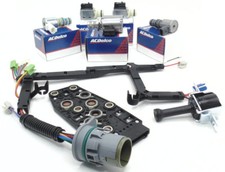
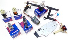
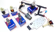
4L60E Master TCC Lock-Up Solenoid Kit (1993–2005)
Covers both the early on/off years and the later PWM years in one kit, so you can put the correct lock-up solenoid back in whether you are working a 1994 unit or a 2003 one. A clean, correct solenoid is step one before you start chasing valve-body or converter wear on a lock-up complaint.
View the TCC solenoid kit →How to Diagnose a Lock-Up Complaint the Right Way
- Identify the system first. Confirm the year and whether it is on/off (1993–1995) or PWM (1996-up). Everything downstream — the correct solenoid, the expected wiring signal, the valves that can be at fault — depends on this.
- Graph it before you condemn anything. Richard Middleton's 4L60-E EC3 teardown in Transmission Digest is a good model: overlay TCC slip and TCC percentage with VSS, TPS and commanded gear on a scan tool and watch what the PCM does. A healthy system holds slip in a narrow band — his cold, code-free baseline kept it around 38 rpm — and the PCM raises TCC percentage to chase slip as it appears, which means a worn valve can hide behind adapt until the strategy runs out of room. On that car the fix was found by wet-air-testing the TCC regulator and AFL valves, both of which showed significant wear, and overboring them for oversize valves with the unit still in the vehicle [8].
- Read codes and note the exact one. P0740 is a circuit fault; P1870 is slip; P1860 is the PWM solenoid circuit specifically. Do not treat "TCC" as one generic problem.
- Check the fluid. Burnt fluid or bronze debris says the converter and bushings are involved, not just the solenoid. Clean fluid with a slip code leans toward a valve-body or solenoid cause.
- Watch live data. On a PWM unit, verify the TCC PWM duty cycle changes on command and watch actual slip rpm; on an early unit, verify the circuit goes fully on when locked. A commanded apply that leaves high slip indicts the converter or the apply/regulator valve.
- Confirm the hydraulics before the converter. On PWM units, inspect the TCC regulator/apply valve bore and the solenoid snout/drainback valve before condemning the converter — a bore repair or snout kit is a fraction of the cost of a converter and R&R [4][5].
Follow that order and the 4L60E's lock-up quirks stop being mysterious. Most "TCC" problems come down to three questions in sequence: do I have the right system, is the electrical signal correct for that system, and is the hydraulic circuit holding apply pressure. Answer those before you buy a converter. If you are already in the valve body, the valve body rebuild walkthrough and the P0740 diagnosis guide cover the rest.
Sources
- Sonnax — GM TCC Circuits, on how the TCC solenoid strokes the converter clutch/apply valve to switch between apply and release oil, and the difference between on/off and PWM converter control. sonnax.com/tech_resources/137
- Sonnax — 20 Years Later: What's New with 4L60-E PWM Modifications, on the move from simple on/off apply to PWM duty-cycle control, the PWM solenoid feeding the TCC regulator valve, and the added converter valve trains. sonnax.com/tech_resources/214
- Sonnax — GM 4L60E unit overview, reference for the 4L60E electronic control architecture and TCC/PWM apply behavior and target slip. sonnax.com/units/455-4l60-e
- Sonnax — TCC Solenoid Snout Kit, on the cracking OE plastic PWM solenoid snout and the drainback valve that can block converter apply, and the aluminum replacement (including drainback-delete versions for later PWM units). sonnax.com/parts/2506-tcc-solenoid-snout-kit
- Sonnax — TCC Apply Valve Kit, on wear of the TCC apply/regulator valve bore causing loss of converter apply pressure, and the oversized valve repair. sonnax.com/parts/2478-tcc-apply-valve-kit
- Transmission Digest — Wayne Colonna, “4L60E Harsh 1-2 Shift” (April 30, 2021), on TCC slippage complaints setting P1870 and P0894 and putting the transmission into high line pressure mode, on those codes denoting component slippage rather than TCC slippage specifically, and on measuring commanded EPC solenoid amperage with a gauge and DVOM instead of trusting the scan tool PID. transmissiondigest.com/4l60e-harsh-1-2-shift
- Transmission Digest — Jim Dial, ATSG senior technical consultant, “P1870 Revisited” (January 1, 2005), on the 4L60-E P1870 TCC-slip code and converter shudder tracing to wear-out of the torque-converter regulator-valve bore and the resulting loss of converter apply pressure, and on the 2000 model year move to PWM TCC apply adding the torque-converter regulator and enable valve trains. transmissiondigest.com/p1870-revisited
- Transmission Digest — Richard Middleton, “4L60-E EC3 TCC Control and Adapt” (January 1, 2011), on graphing TCC slip against TCC percentage with VSS, TPS and commanded gear, on the PCM raising TCC percentage to adapt around slip (roughly 38 rpm on a healthy cold baseline), and on the wet-air-test findings that led to overboring the TCC regulator and AFL valves for oversize valves. transmissiondigest.com/4l60-e-ec3-tcc-control-and-adapt