Every 4L60E looks like every other 4L60E across a parking lot. Square pan, aluminum case, cooler lines on the passenger side. That resemblance is what gets people in trouble. GM built this unit from 1993 until 2013 and changed the case, the pump, the pan, the connector and the shaft during that run, and a core that bolts up is not the same thing as a core that works.
This is the walk-around I do before buying a core or ordering a hard part: case pieces, tailhousing bolt pattern, case connector, pan and dipstick generation, converter, and the input speed sensor rollout that will smoke a rebuild in a few miles if you mismatch the pump and shaft. Every spec below is sourced.
The 60-second core check: Look at four things in this order — (1) is the bellhousing cast into the case or bolted on, (2) is the rear output/adapter pattern a four-bolt square or a six-bolt hex, (3) does the case connector have 12 pins or 13, and (4) does the pump cover have an input speed sensor boss, and is it drilled. Those four answers put a core in the right decade and tell you which parts catalog page you are shopping.
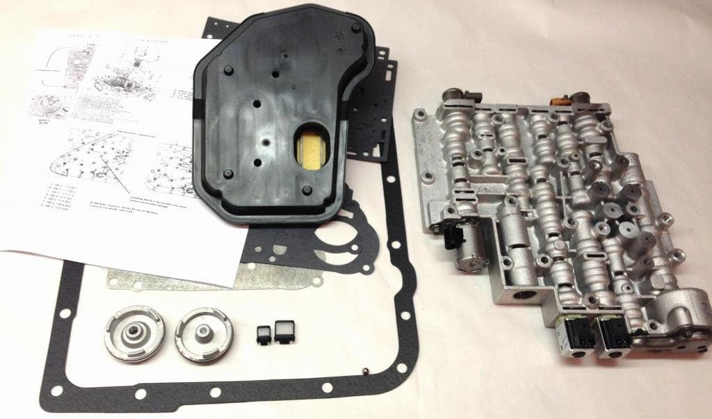
One-piece case vs removable bellhousing
The most visible break in the 4L60E line is the bellhousing. Early units carry the bell cast into the main case as one piece. The late unit is a three-piece case of cast aluminum alloy — bellhousing, main case, and tailhousing — with the bell bolted to the front of the case, which is what let GM hang different engine bolt patterns on the same core casting [1].
The changeover was not a single model year. Novak Conversions dates the removable bellhousing to 1996 behind the 4.3L V6, broader release against the V8s in 1997, and full implementation across GM's rear-drive car and truck platforms, 2WD and 4WD, by 1998 [1]. So a 1996 or 1997 core is a coin flip. You have to look, not go by the year on the door jamb.
The six-bolt hex tail pattern
The other case-level tell is at the back. Per Novak, the key distinction of the later 4L60E (1996–2010) from the early 4L60E (1992–1997), the 4L60 (1990–1992), and the 700R4 (1982–1989) is the six-bolt "hex" rear output or tailhousing/adapter pattern. The earlier units used a four-bolt square pattern at the adapter or tailhousing [1].
That one detail decides whether your existing 2WD tailhousing or 4WD transfer case adapter will bolt on, and it works even when the bellhousing has already been pulled and set on a different shelf. Two-wheel-drive units get a tailhousing and a longer output shaft; four-wheel-drive units get an adapter assembly and a shorter shaft [1].
Physical numbers worth writing on the whiteboard
- Overall package length: 21.9 in on the late unit [1]
- Weight: 146 lb dry, 162 lb wet [1]
- Input shaft: 30 splines [1]
- Fluid capacity: 8.4 qt behind the 9.64 in (245 mm) converter, 11.4 qt behind the 11.81 in (300 mm) converter, up to 14 qt with a deep pan — Dexron III or Dexron VI [1]
- RPO codes: M30 = 4L60E, M32 = 4L65E, M70 = 4L70E [1]
12-pin vs 13-pin: the electrical fingerprint
The case connector on the passenger side is the fastest way to sort early from late electrically, and it maps directly onto whether you have a PWM torque converter clutch or a simple on/off apply.
Per Sonnax, the '95-later 4L60E, 4L65E and 4L70E units with PWM/EC3 (electronically controlled capacity clutch) control are identified by the 13-pin case connector, a PWM/TCC solenoid, and a PWM pump — five solenoids total. The '93–'94 non-PWM units are identified by the 12-pin case connector and only a 3-2 solenoid in the valve body — four solenoids [2].
This is not trivia. Sonnax notes that its Sure Cure components are compatible across both generations except the TCC apply valve 77805E-K that installs in the pump, which fits PWM units only [2]. Order that valve for a 12-pin core and it goes back in the box.
| Feature | '93–'94 non-PWM | '95-later PWM/EC3 |
|---|---|---|
| Case connector | 12 pin | 13 pin |
| Solenoid count | Four | Five |
| TCC control | On/off | PWM / controlled slip |
| Pump | Non-PWM | PWM pump |
| Extra valve body solenoid | 3-2 only | 3-2 plus PWM/TCC |
Identification per Sonnax Sure Cure SC-4L60E application notes [2].
1998: the deep pan, the dipstick, and a chamfer on the valve body
1998 is the year that catches people swapping cores between trucks. Sonnax documents that the 4L60E series got a deeper transmission oil pan on the C/K/G trucks and vans in 1998 to increase fluid capacity, and the deep pan came with a longer dipstick, a longer tube, and a taller dipstick stop bracket. Standard-pan models got a revised stop bracket the same height as the old one but shorter than the deep-pan stop. After 1998, every model except the Corvette used a bracket [3].
The part that bites is on the valve body. Also in 1998, GM added a small chamfer on the valve body to accept the new-design stop brackets. Pre-1998 valve bodies do not have that chamfer, so a new-design bracket will not install on them. The old-style bracket will physically go on a '98-later standard-pan unit, but it gives up the improvement [3].
Get the combination wrong and the dipstick lies to you. Sonnax's testing puts real numbers on it: a regular-pan setup missing its bracket can underfill by up to 0.5 quart, and a deep dipstick without its bracket can underfill by up to 0.75 quart. Run a deep dipstick and tube in a regular-pan unit and the stick reads in the normal band while the actual capacity is well below where it should be [3]. Dipsticks are deliberately made longer than needed so they bottom on the stop bracket; remove the stop and the reading is meaningless.
Bench habit: When a core comes in, keep the pan, the dipstick, the tube, and the stop bracket together as a set and tag them with the donor vehicle. If you are mixing a '98-later deep pan onto an earlier case, you need the matching stick, tube, and bracket — and the valve body has to be the '98-later chamfered casting for the new bracket to seat [3].
The converter side of the late bellhousing
Once the bellhousing came off the case, converter combinations multiplied. The 300 mm converter arrived with the late units, and it brings its own set of measurements that are worth checking on the bench rather than discovering after the pump grenades.
Sonnax gives the two numbers that matter. Stab depth is measured by bolting the flexplate to the engine, pushing the converter in until the drive slot bottoms on the pump gear lugs, and measuring the gap between the flexplate and the converter mounting pads. That gap should be a minimum of 0.125 in to avoid damaging the pump and no more than 0.250 in to prevent pump gear failure [4].
On overall height, the OE spec for 300 mm converters is 6.550 in, with the Corvette unit the exception at 6.254 in to 6.275 in. Sonnax flags the 2002–2003 Bravada, Envoy, and TrailBlazer 4.2L converter (code VJCX, Dacco B-85) specifically: its published spec was 6.500 in, most measure about 6.450 in, and the correct height should be 6.550 in — which is why those units show higher-than-normal pump gear failures [4]. That converter is also easy to spot: it is the only GM 300 mm unit whose impeller fits inside the front cover rather than the other way around [4].
If you correct stab depth with a shim between the flexplate and the converter pads, Sonnax warns that a converter 6.450 in or shorter will pull the pilot out of the crankshaft once the shim goes in. The right fix is a taller impeller hub, not a thicker bearing race — adding 0.060 in of internal clearance makes the converter less efficient, raises stall, and raises operating temperature [4].
The sensor half: how the ISS changed the front of the unit
Everything above is case and hardware. The last set of changes is the one that will actually destroy a rebuild, and it is the input speed sensor.
The OSS/VSS side is straightforward: the vehicle speed signal comes off the output shaft in the tailhousing on 2WD units, and off the transfer case on 4WD [1]. The input speed sensor is the complicated one, because GM staged it in over three model years and shipped interim parts that look correct and are not.
Per ATRA's GEARS magazine (March 2008), the major 4L60E/65E update for the 2006 model year actually started in 2005 and introduced an input speed sensor on some models, with full implementation for 2007-and-later. The ISS lets the computer calculate input speed, and two DTCs were added for it: P0716 and P0717 [5].
Making room for that one sensor took a list of hardware changes, all documented in the same article [5]:
- The reverse boost pressure regulator valve lineup was shortened
- Pump casting changes relocated the S3 bore boss
- Casting changes relocated the TCC release bore
- Stator support sleeve passages changed
- Reluctor teeth were added to the turbine shaft and the sealing ring grooves were repositioned
- The transmission wiring harness changed; on units without an ISS, the sensor hole is plugged
The five pump designs
ATRA breaks the pump assemblies into five styles. This is the table to read before you buy a used pump [5]:
| Era | ISS boss | Stator support sleeve | Pressure regulator valve train |
|---|---|---|---|
| 1997–2005 | None | 1st design | 1st design |
| 2005 1st design | None | 1st design | 2nd design |
| 2005 2nd design | Present but not drilled | 1st design | 2nd design |
| 2006 | Drilled on ISS models | 2nd design | 2nd design |
| 2007 and later | All present and drilled (rubber plug if no ISS) | 2nd design | 2nd design |
The 2006-and-later combination requires an ISS-style turbine shaft, or at least a shaft that relocates the sealing rings to the new positions [5]. ATRA's warning on mismatching this is not softened: get the stator support assembly and input shaft interchange wrong and you will destroy the planetary gear set, smoke the clutches, and cause a general meltdown within a few miles — possibly on the test drive [5].
Shaft and pump cover part numbers
Turbine shafts carry an ID mark: a 9.5 mm by 0.5 mm groove on the shaft. Some shafts have it and some do not, so the groove confirms an identity but its absence does not rule one out [5]. The GM numbers ATRA lists:
| Turbine shaft (converter size) | Non-ISS | ISS-equipped |
|---|---|---|
| 245 mm / 258 mm | 17803688 | 24232438 |
| 280 mm / 300 mm | 17803687 | 24230653 |
| 300 mm HD / 300 mm M70 | 17803686 | 24230654 |
| 258 mm PHT | 17803685 | — |
Pump cover kits: 12491417 and 12491421 for 1998–2005; 24236486 and 24236489 for 2006-later non-PHT; 24239202 for 2006/07 PHT [5].
The decision rule from the same article is short enough to tape to the bench: if the unit has an ISS or an input shaft with a boss, you must use an ISS-equipped pump assembly. If the unit has no ISS but the input shaft has a boss, you still need the ISS-type stator support sleeve. If the input shaft looks like the earlier style, use the earlier pump assembly [5]. Get it wrong and the symptoms are line pressure problems, TCC or clutch apply problems, release crossleaks, or planetary failure.
4L60E Input Speed Sensor, OEM 24235714
If your core has a drilled ISS boss and a reluctor turbine shaft, this is the sensor that belongs in it — the one that feeds the ratio math behind P0716 and P0717. Worth replacing while the pump is out rather than pulling it back apart later. Also grab the matching output speed sensor 24232617 and, if you are separating a late case, the bell housing bolt kit 551652. Full catalog: CoreTransmissionParts 4L60E collection.
View the 4L60E input speed sensor →Three bench checks before you commit a pump
You do not always have the donor vehicle or the year. Sonnax publishes a three-check method for verifying that a stator, pump cover, and input shaft belong together, and it works on parts alone [6]:
- Note the sealing ring locations on the input shaft. There are several shaft variations and the ring positions are the giveaway. The anomaly to watch for is a pump cover with no ISS hole drilled paired with a reluctor-style stator and no reluctor on the input shaft [6].
- Draw a line through the centers of the pump bolt holes and note whether the converter feed hole sits slightly to the right or left of that line [6].
- Look at the converter feed and lube holes in the stator and note whether they are directly in line with one another or the feed hole sits to the right of the lube hole [6].
The pattern that ties them together: on earlier pumps the converter feed hole is just to the right of the line and the stator's feed and lube holes are directly in line. On later-model and GM's most recent pumps, the feed hole is just to the left of the line and the stator's feed hole sits to the right of the lube hole [6]. If the stator is misaligned or wrong for the pump, Sonnax lists the outcomes as no movement, converter charge concerns, input shaft failure, and converter damage [6].
Putting it together: how to spec a core
- Bellhousing: cast in, or bolted on? Bolted on puts you in the 1996-and-later family, and the bell can be swapped to suit the engine [1].
- Rear pattern: four-bolt square is early, six-bolt hex is late (1996–2010). This decides your tailhousing or transfer case adapter [1].
- Case connector: 12 pins means '93–'94 non-PWM with four solenoids; 13 pins means '95-later PWM/EC3 with five [2].
- Pan and stick: a deep pan on a C/K/G core points to 1998-and-later, and the stop bracket, dipstick, tube, and valve body chamfer all have to agree [3].
- Pump cover: no ISS boss, undrilled boss, or drilled boss — then match the stator support sleeve, PR valve train, and turbine shaft to that answer [5].
- Converter: confirm overall height and check stab depth at 0.125 to 0.250 in before you button anything up [4].
Six looks and one measurement. Long production histories always come with interchange traps, and the fix is knowing which decade of parts you are holding before the case goes together.
Related reading on this site: 4L60E RPO and casting identification, 4L60E speed sensors (VSS/ISS/OSS), and 2WD vs 4WD tailhousings.
Sources
- Novak Conversions — "The Novak Guide to the GM 4L60-E Automatic Transmission." Backs the three-piece late case (bellhousing, main case, tailhousing), the removable bellhousing timeline (1996 behind the 4.3L V6, broader in 1997, full implementation by 1998), the six-bolt hex rear output/adapter pattern on 1996–2010 units vs the four-bolt square pattern on earlier units, 21.9 in package length, 146 lb dry / 162 lb wet, 30-spline input, 8.4 / 11.4 / up to 14 qt capacities with Dexron III or VI, VSS at the output shaft or transfer case, and RPO codes M30 / M32 / M70. novak-adapt.com/knowledge/transmissions/automatic/4l60e
- Sonnax — Sure Cure Kit SC-4L60E application notes. Backs the 12-pin vs 13-pin case connector split, four solenoids on '93–'94 non-PWM units vs five on '95-later PWM/EC3 units, the PWM pump and PWM/TCC solenoid, and the TCC apply valve 77805E-K fitting PWM units only. sonnax.com/parts/3029-the-sure-cure-kit
- Sonnax (Jason Larochelle) — "How to Avoid a Dipstick Move in 4L60-E Series Transmissions." Backs the 1998 deep pan on C/K/G trucks and vans, the longer dipstick/tube/stop bracket, the 1998 valve body chamfer that blocks new-design brackets on pre-1998 valve bodies, the Corvette exception, and the 0.5 qt and 0.75 qt underfill figures. sonnax.com/tech_resources/941-how-to-avoid-a-dipstick-move-in-4l60-e-series-transmissions
- Sonnax (Ed Lee) — "Overall Height Issues and Pump Gear Problems: 4L60-E, 300mm Converter, 4.2L Engine, Code VJCX." Backs the 0.125–0.250 in stab depth window, the 6.550 in OE overall height for 300 mm converters, the 6.254–6.275 in Corvette exception, the VJCX 6.500 in / 6.450 in actual discrepancy on 2002–2003 Bravada, Envoy and TrailBlazer 4.2L units, and the shim / bearing race / taller hub correction options. sonnax.com/tech_resources/10-overall-height-issues-and-pump-gear-problems-4l60-e-300mm-converter-4-2l-engine-code-vjcx
- ATRA / GEARS Magazine, March 2008 (Lance Wiggins), "4L60/65/70E: Parts Interchange, and Immediate Failure after Rebuild." Backs the 2005–2007 ISS rollout, DTCs P0716 and P0717, the six hardware changes made to accommodate the ISS, the five pump designs and their stator support sleeve / PR valve train pairings, the 9.5 mm x 0.5 mm turbine shaft ID groove, the non-ISS and ISS turbine shaft part numbers, and the pump cover kit numbers. atracom.blob.core.windows.net/gears/2008/2008-03/2008_3_26.pdf (PDF)
- Sonnax (Caleb Perham) — "4L60-E Series Input Shaft, Stator & Pump Cover Compatibility: Three Easy Checks." Backs the three-check bench method, the sealing-ring-location variations, the undrilled-ISS-hole anomaly, the converter feed hole position relative to the pump bolt hole centerline on early vs late pumps, and the failure modes from a wrong or misaligned stator. sonnax.com/tech_resources/1419-4l60-e-series-input-shaft-stator-pump-cover-compatibility-three-easy-checks