P0700 is the code that sends more 5R55W transmissions to the wrong repair than any other. It reads "Transmission Control System Malfunction," which sounds like it names a failed part. It does not. It is a flag the powertrain control module raises to tell the generic side of OBD-II that a transmission fault is stored somewhere else. The repair information is in that other code, and on a 2002 to 2005 Explorer or Mountaineer there is a good chance your scan tool cannot see it.
That is the whole job here: understand what the PCM is telling you, go get the code that actually matters, then work the hydraulics and electrics with real numbers instead of parts-cannon guesses.
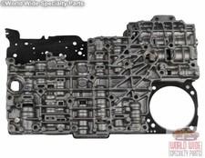
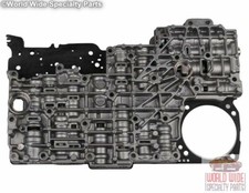
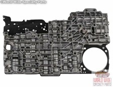
There Is No TCM on This Truck
Start with the architecture, because half the bad diagnoses on this unit come from assuming a separate transmission controller exists. On the Explorer and Mountaineer 5R55W the transmission is run by the PCM, as part of the EEC-V system. The same module handling fuel and spark schedules the shifts, commands the pressure control solenoids, and stores the transmission codes. There is nothing to unplug and swap on a bench.
The control hardware it is driving is documented cleanly by Jesse Zacarias in Transmission Digest: four on/off shift solenoids whose job is to align valves in the valve body, three variable force solenoids (PC-A, PC-B and PC-C) that control the rate of apply and release for the clutch packs and the intermediate and overdrive bands, and one pulse width modulated solenoid for converter clutch control. All of it lives on one solenoid body assembly inside the pan.
The PCM watches that hardware through the digital transmission range sensor, the turbine shaft speed sensor, the output shaft speed sensor and the transmission fluid temperature sensor. When any of those monitors goes out of range, the fault gets written to continuous memory. P0700 is what shows up on the generic side when one of those stored faults is MIL-worthy.
Why Your Scanner Shows P0700 and Nothing Else
This is the part worth reading twice. Ford's own diagnosis procedure for the 5R55W/S splits continuous memory DTCs into two kinds: emission-related codes that illuminate the malfunction indicator lamp, and non-emission codes that never illuminate it at all. Both are stored. Only one lights the dash.
The strategy on the emission-related side is specific. The PCM stores the DTC on first detection and treats it as pending without lighting the lamp. If the same fault is detected on the next drive cycle, the MIL comes on. The lamp goes back out after three consecutive clean drive cycles, and the record is erased after 40 to 80 warm-up cycles or a PCM reset.
Now look at what lives on the non-emission side of a 5R55W. P1714 and P1715 for SSA and SSB mechanical failure. P1716 and P1717 for SSC and SSD. P1746 and P1747 for a PC-A solenoid circuit open or shorted to ground. P1783 for a transmission overheat condition at 270°F (127°C). P1702 for an intermittent digital TR sensor signal. Those are the codes that tell you what is broken, and a basic generic-only code reader will not show you one of them.
So step one on any 5R55W P0700 is not a wiring diagram. It is getting a tool that can run the Ford quick test and read enhanced PCM data. Everything downstream depends on it.
Read the Companion Code, Then Read the Symptom It Predicts
Ford's DTC table for this transmission pairs each code with the behavior it should produce. Use that as a sanity check: if the code and the customer complaint do not match, the code is a symptom of something else, not the fault.
- P0745 / P1746 (PC-A circuit or mechanical): an open circuit produces maximum PC-A pressure, harsh engagement, slipping in gear and incorrect 3rd. P1747, a short to ground, produces the opposite: low pressure, limited engine torque, slipping.
- P0750 / P0753 (SSA): shorted gives no 4th or 5th; open gives no 1st.
- P1715 (SSB mechanical): shorted gives no 1st; open gives no 3rd.
- P0731 through P0735 (ratio codes): improper gear selection, shift errors, and engine RPM higher or lower than expected for the commanded gear.
- P0740 / P0743 / P1740 (TCC solenoid): a short stalls the engine at low idle; an open means the converter clutch never engages.
- P1713 / P1718 (no TFT change): increased pressure control pressure, incorrect TCC scheduling, harsh engagements and shifts.
Pete Luban of ATSG made the same point in Transmission Digest's "False Pretenses": on a 2002 Explorer storing P0732, P0735 and P0775, the P0775 was a pressure control performance code, not a circuit fault, and the real problem was a worn servo pin bore. If the truck is also running in a failure strategy with a flashing O/D OFF light, our 5R55S limp mode guide maps each code to the failure response Ford programs for it.
Note the footnote Ford attaches to codes like P0731 through P0735, P0741, P0745 and P1746: they can be set by non-electronic transmission hardware conditions. That single line is why a solenoid pack does not fix most of these. The code is electrical only in the sense that the PCM noticed the problem electrically.
Check Fluid Before Wiring
On this family, fluid history is not a throwaway step. Sonnax's Bob Warnke documents that the factory ATF fill in 5R55E, W, S and N units prior to May 2005 used an early MERCON V that degraded the solenoids. Ford released an interim additive package, 4L2Z-19B546-AB, fluid XL-11, under bulletin FSA 04B22, to install into customer and inventory vehicles. The final resolution was revised MERCON V, part number XT-5-QM, in the black quart container.
Warnke's warning about it is the practical part: if you service a unit and any trace of the questionable fluid stays in, the service life of the next solenoid is reduced. Degraded fluid gives you pressure control codes, ratio codes and erratic shifts, all of which report upstream as P0700. Get the old fluid out, and use MERCON V, not MERCON LV.
The Electrical Test, With Real Numbers
The transmission 16-pin case connector is where this test happens, and it is also the single most common corrosion point on the truck. Inspect it before you measure anything. Ford's specifications, taken at that connector with the harness disconnected:
- Shift solenoids SSA, SSB, SSC, SSD: 16–45 ohms
- TCC solenoid: 9–16 ohms
- Pressure control solenoids PC-A, PC-B, PC-C: 3.3–7.5 ohms
- ISS, OSS and TSS speed sensors: 266–390 ohms at 4°F, 325–485 ohms at 70°F, 492–738 ohms at 302°F
- Open circuit threshold: anything above 5 ohms through a circuit is an open
- Short to ground threshold: anything measuring 10 k-ohms or less to ground is a short
Solenoid terminals reading less than 5 ohms to chassis ground mean the solenoid body assembly is shorted internally and gets replaced. The TFT sensor is checked across terminals 2 and 12 of that same connector and compared against the temperature/resistance table — out of spec means the solenoid body assembly, because the sensor is part of it.
One more thing Warnke flags and everybody skips: inspect the grounds at the battery and the PCM. A soft ground on a module that is controlling variable force solenoids by current produces exactly the kind of intermittent pressure-control fault that sets P0700 and then hides.
Line Pressure: The Test That Separates Electrical From Hydraulic
Once codes and resistance check out, put a gauge on it. Ford's line pressure specifications for the 5R55W in Explorer and Mountaineer:
- 4.0L, at idle: P and N 75–120 psi • R 145–190 psi • D, 3, 2, 1 80–110 psi
- 4.0L, WOT stall: R 282–350 psi • D, 3, 2, 1 228–263 psi
- 4.6L, at idle: P and N 75–120 psi • R 175–215 psi • D, 3, 2, 1 100–135 psi
- 4.6L, WOT stall: R 282–350 psi • D, 3, 2, 1 228–263 psi
Ford's own interpretation of the results is a shortcut worth memorizing. High at idle in all ranges points at the wiring harness, boost valve, PC solenoid or main regulator valve. Low at idle in all ranges points at low fluid level, a faulty intake screen or filter seal, loose valve body bolts, pump or pump gasket leakage, case leakage, or a faulty valve body or separator plate.
You can also command pressure directly. The PCM supports setting PC solenoid pressure from 0 to 90 psi in 15 psi increments through the scan tool's output test mode. Step it and watch the gauge follow. A circuit that will not track commanded pressure is hydraulic, and the codes were downstream of the leak all along.
Where the Real Fault Usually Is: Valve Body Bore Wear
Here is the mechanism behind most 5R55W P0700 companions on a high-mileage unit. Warnke's inspection order for these valve bodies is specific: the TCC modulator bore and the main regulator bore wear first, because they are the most active. As cycle rate climbs, and it climbs hardest in city traffic, the VFS 1, 2 and 3 modulator bores wear next, reducing clutch and servo pressure.
The adaptive strategy hides it for a while. The PCM compensates for the falling pressure, which is exactly why the truck drives acceptably for months before anything sets. Then wear passes the point adaptive can cover and you get gear ratio codes or slippage. Sonnax's vacuum test guide lists the VFS1 and VFS2 modulator control valves against flare shifts, low line pressure and pressure control out-of-range codes — the exact code families that flag P0700 on the generic side.
Warnke's line on this deserves repeating to every tech who reaches for a solenoid pack: often the solenoid or the servo pin bore is blamed, but actually the VFS modulator valves cannot supply enough pressure.
The bench test that proves it is the wet air test, and it works in the vehicle. Remove the solenoid base plate and reattach it over the separator plate, then inject ATF along with low air pressure of 40 to 60 psi into the circuits. A healthy valve body strokes its valves with no excessive leakage past them and no bubbling from the exhaust slots. Excess wear shows up as leakage around a valve or slot — and Warnke notes that same leakage aerates the fluid in service, which raises the apparent level and vents fluid from the case, giving you a level reading you cannot trust while you are chasing the original complaint.
The Solenoid Pack Traps
When you do replace the solenoid assembly, two things bite people.
First, the base plate and filter are not interchangeable between the N and the W/S even though the assembly looks like it is. Warnke is explicit: if the base plate or filter are mixed, the unit loses reverse, TCC apply and solenoid oil pressure. If someone has been in the pan before you and the truck came out worse, check what base plate is on it before you diagnose anything else.
Third, the pack design has to match the model year. ATRA's 2013 seminar notes list the early pack, 1L2Z-7G391-AG, for 2002-03 Ford W or S units and the 2003 Lincoln, and the later pack for 2004-on Ford units and 2004-06 Lincolns, where Ford recommends only the updated 9L2Z-7G391-A. ATRA traced flare shifts after a rebuild to the wrong pack for the year, because the design changes alter solenoid output pressure.
Second, loss of prime. The variable force solenoids are tested and shipped wet, but the lubricant drains off in handling. Before installing the assembly, fill the circuits with new MERCON V or the XL-11 additive and pull fluid through the solenoid with vacuum. And on any unit built after 2002, do the adaptive relearn along with the solenoid service — skipping it produces shift quality complaints that get blamed on the new part.
5R55W solenoid block pack with filter → or browse all 5R55W parts
When Everything Electrical Checks Out
A case from Gears is the right note to end the diagnosis on. Rob Faucett describes a 2006 Explorer with a 5R55W that developed a severe delay in forward engagement once warm, then started to bind in reverse and pull forward in neutral. The technician checked for codes, confirmed the computer could operate the solenoids and read the sensors, and found nothing wrong electrically. On teardown, only the forward clutches were damaged — unusual on a unit that normally shows servo pin wear and burnt bands.
The fault turned out to be a leak between an end plug and the valve body at the forward engagement valve, found by vacuum testing. An o-ringed end plug fixed it, and a second vacuum test verified the repair before the unit went back together.
That is the shape of a hard 5R55W problem. The electrical side reports clean, the code list is thin, and the fault is a few thousandths of clearance in a casting. P0700 will never point at it. Vacuum testing will.
The Order of Operations
- Pull codes with a tool that reads Ford enhanced data. Record freeze frame. Fix engine-side codes first, since engine performance faults affect shift scheduling.
- Check fluid level and condition hot, on level ground. Confirm MERCON V, and confirm the pre-2005 fluid was fully purged if the unit has history.
- Inspect the 16-pin case connector and the battery and PCM grounds before you measure.
- Measure solenoid and speed sensor resistance against the specs above, and check every terminal for a short to ground.
- Put a gauge on the line pressure tap and compare to the table for your engine. Command PC pressure in 15 psi steps and confirm the gauge follows.
- If pressure will not track command, drop the pan and wet air test the valve body at 40 to 60 psi. Vacuum test the suspect bores.
- Repair the bores that fail, service the solenoid assembly correctly, and run the adaptive relearn.
Need parts for this job?
Solenoid packs, filters, valve body kits, bands, servo kits and full rebuild kits for the 5R55W and 5R55S, with real fitment notes instead of guesswork.
Shop 5R55 parts →FAQ
Does P0700 by itself tell me what is wrong with a 5R55W?
No. P0700 is a transmission control system fault flag, not a diagnosis. On a 5R55W the PCM stores the real fault as a separate DTC in continuous memory, and P0700 exists so the generic OBD-II side knows to look. Until you pull the manufacturer-specific codes with a scan tool that can run the Ford quick test, you have no repair information at all. Anyone selling you a solenoid pack off a bare P0700 is guessing.
Why does my scanner only show P0700 and nothing else?
Because most of the useful 5R55W codes are non-emission codes that never illuminate the MIL and do not appear in the generic powertrain code list. Ford's own diagnosis procedure splits continuous memory DTCs into emission-related codes that light the MIL and non-emission codes that never do. The P17xx family on this unit, including P1714 and P1715 for SSA and SSB mechanical failure and P1783 for a 270 degree F overheat, lives on the enhanced side. Get a tool that reads Ford enhanced PCM data before you condemn anything.
What solenoid resistance values are correct on a 5R55W?
Ford's specifications, measured at the transmission 16-pin case connector with the harness unplugged, are 16 to 45 ohms for shift solenoids SSA, SSB, SSC and SSD, 9 to 16 ohms for the TCC solenoid, and 3.3 to 7.5 ohms for the pressure control solenoids PC-A, PC-B and PC-C. Any of those terminals reading less than 5 ohms to chassis ground means a shorted solenoid body assembly. Speed sensors should read 325 to 485 ohms at 70 degrees F.
Can a fluid problem set P0700 on an Explorer?
Yes, and on this family it is common enough to check first. Sonnax documents that the factory fill before May 2005 was an early MERCON V that degraded the solenoids, which Ford addressed with interim additive 4L2Z-19B546-AB under bulletin FSA 04B22 and finally with revised MERCON V in the black quart. Degraded or low fluid produces pressure control and ratio codes that all report upstream as P0700. Check level and condition before you touch a wiring diagram.
Will clearing P0700 make it stay gone?
Only if you fixed the fault underneath it. Ford's strategy stores an emission-related fault as pending on first detection and lights the MIL on the second consecutive drive cycle, then turns the lamp off after three clean drive cycles and erases the record after 40 to 80 warm-up cycles. Clearing codes just restarts that clock. If the companion code was a ratio or pressure control fault, it will be back within a few drive cycles.
Sources
- Ford Motor Company — 2002 Explorer/Mountaineer workshop information, "5R55W/S Diagnosis" (archived service PDF). Backs every OEM specification in this article: the split between emission-related continuous memory DTCs that illuminate the MIL and non-emission DTCs that never do, the pending-then-MIL-on-second-drive-cycle strategy, the three clean drive cycles to extinguish the lamp and 40 to 80 warm-up cycles to erase; the DTC table entries for P0731–P0735, P0740/P0743, P0745/P1746, P1747, P0750/P0753, P1714–P1717, P1713/P1718, P1702 and P1783 at 270°F (127°C); solenoid resistance of 16–45 ohms for SSA–SSD, 9–16 ohms for TCC and 3.3–7.5 ohms for the PC solenoids; speed sensor resistance of 266–390 ohms at 4°F, 325–485 ohms at 70°F and 492–738 ohms at 302°F; the 5-ohm open and 10 k-ohm short thresholds; TFT measured across 16-pin connector terminals 2 and 12; the line pressure specification table for 4.0L and 4.6L; the high-at-idle and low-at-idle result interpretations; and PC solenoid pressure commanded 0–90 psi in 15 psi increments. Ford 5R55W/S Diagnosis (archived PDF)
- Sonnax — "Figuring Out the 5R55 Alphabet," Bob Warnke, September 19, 2007. Backs the wear order and service traps: the TCC modulator bore and main regulator bore wear first due to activity, then the VFS 1, 2 and 3 modulator bores, reducing clutch and servo pressure until adaptive strategy can no longer compensate and gear ratio codes or slippage appear; the note that the solenoid or servo pin bore is often blamed when the VFS modulator valves simply cannot supply enough pressure; the base plate and filter being the critical non-interchangeable pieces between N and W/S, with mixing costing reverse, TCC apply and solenoid oil pressure; the pre-May-2005 MERCON V fluid problem, interim additive 4L2Z-19B546-AB (XL-11) under bulletin FSA 04B22 and revised MERCON V XT-5-QM in the black quart; VFS solenoid loss of prime and priming with vacuum; the post-2002 adaptive relearn; inspecting the grounds at the battery and PCM; and the wet air test at 40 to 60 psi with the solenoid base plate reattached over the separator plate, including aeration raising apparent fluid level and venting from the case. sonnax.com
- Sonnax — "Ford 5R55W/S Vacuum Test Guide," February 21, 2013. Backs the valve-to-symptom map used in the valve body section, including the VFS1 and VFS2 modulator control valves listed against flare shifts, low line pressure and pressure control out-of-range codes, the pressure regulator valve against delayed engagement, soft shifts and low line rise, and the solenoid feed limit valve against no lockup, overheating and delayed engagement. sonnax.com
- Transmission Digest — "Understanding the 5R55S/W Initial Engagements," Jesse Zacarias, November 1, 2012. Backs the control architecture: four on/off shift solenoids whose main function is to align the valves in the valve body, three variable force solenoids (PCA, PCB, PCC) controlling the rate of apply and release of the clutch packs and the intermediate and overdrive band, one PWM solenoid for TCC control, and the transmission range sensor signalling the PCM on range selection. transmissiondigest.com
- Gears Magazine (ATRA) — "Going Nowhere Fast... 5R55W Delayed Forward Engagement," Rob Faucett, September 2017. Backs the closing case study: a 2006 Explorer 5R55W with severe warm delayed forward engagement that later bound in reverse and pulled forward in neutral, no electrical faults found, only the forward clutches damaged, and a vacuum test that revealed a leak between the end plug and the valve body at the forward engagement valve, repaired with an o-ringed end plug and verified by retest. gearsmagazine.com
- Sonnax — "Ford 5R55S, 5R55W Valve Body Layout," December 12, 2014. Backs the repair-part mapping referenced for these wear areas, including the oversized solenoid and converter feed limit valve kit 56947J-61K listed against no lockup, delayed engagement, overheating and front lube failure, and the tooling required for each bore reconditioning kit. sonnax.com
- ATRA — 2013 Technical Seminar manual, "Ford 5R55W/S Erratic Transmission Operation" (pp. 112-120). Backs the year-specific solenoid pack part numbers 1L2Z-7G391-AG (2002-03 Ford, 2003 Lincoln), 4L2Z-7G391-AA and the updated 9L2Z-7G391-A (2004-on Ford, 2004-06 Lincoln), and the flare shifts caused by the wrong pack design. atracom (PDF)
- Transmission Digest — "False Pretenses," Pete Luban (ATSG). Backs the 2002 Explorer case with P0732, P0735 and P0775 where P0775 was a pressure control performance code and servo pin bore wear was the cause. transmissiondigest.com