A 66RFE does not know what gear it is in. It works it out, many times a second, by dividing input shaft speed by output shaft speed and matching the answer to a known ratio. Two small magnetic sensors on the left side of the case supply those numbers. When one of them lies, the controller cannot tell a bad signal from a slipping clutch, so it does the safe thing: sets a code, kills the transmission relay and drops the truck into limp mode. That is why a $40 sensor, a chafed wire or a cracked thrust bearing can all produce the same complaint at the counter.
The 66RFE is the gas-engine six-speed in the Ram 2500 and 3500. The 2018 Ram 2500 Heavy Duty specification sheet lists it behind both the 5.7L and the 6.4L HEMI, with ratios of 3.23, 1.84, 1.41, 1.00, 0.82 and 0.63, and 4.44 Reverse. For 2019 the 6.4L moved to the ZF 8HP75 eight-speed, per FCA's 2019 spec sheet. The 66RFE shares its speed sensors, sensing strategy and diagnostic logic with the 45RFE, 545RFE and 68RFE, so the factory and ATSG data below apply directly.
What the Two Speed Sensors Read
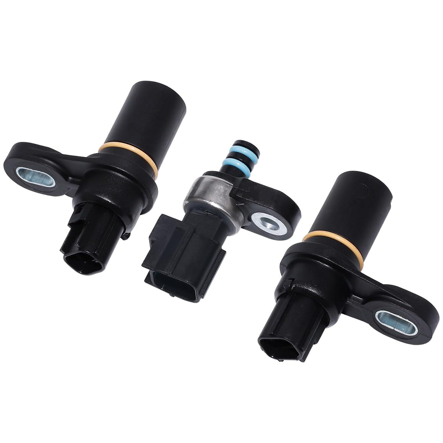
Chrysler's service information describes the input and output speed sensors as two-wire magnetic pickup devices that generate AC signals as rotation occurs, mounted in the left side of the case and treated as primary inputs to the controller. They are variable reluctance sensors: a permanent magnet and a coil, with no power feed. As each tooth passes the tip, the magnetic field concentrates and then collapses, and that induces an AC sine wave the controller counts.
- Input speed sensor. Reads a 60-tooth tone wheel on the input clutch hub, per the Chrysler P0715 theory of operation. ATSG's 68RFE manual places it on the input clutch housing. This is turbine speed.
- Output speed sensor. Reads the 30 teeth of the park gear. This is output shaft speed.
ATSG lists four things the controller calculates from that pair of signals: transmission gear ratio, speed ratio error detection, Clutch Volume Index (CVI) calculation and torque converter clutch slippage. ATSG also notes that both sensors are the same part and will interchange, and that a new sensor reads 535 ohms at room temperature.
That list is the key to the whole symptom picture. Ratio is how the controller confirms each shift. CVI is how it learns clutch fill volumes, so a noisy input signal corrupts the adaptives. TCC slip is engine speed against input speed, so a bad input signal can look like a slipping converter clutch.
Symptoms of a Bad 66RFE Speed Sensor
- Limp mode, stuck in one gear. When the controller decides damage could result, it shuts off the transmission control relay. Per ATSG, the unit then holds 4th gear in Drive and 2nd in the 2 or L position. Many owners describe it as "stuck in 2nd" because they launch in the low position.
- Check engine light with P0715 or P0720, or a string of gear ratio codes, P0731 through P0736.
- Erratic or harsh shifts before the code sets, especially on the input sensor, because CVI and shift timing are built on that signal.
- Code takes a while to light the MIL. Chrysler states that P0715, P0720 and P1794 can each take up to five minutes of problem identification before the MIL comes on. A truck that shifts badly for a few minutes and then lights up is consistent with that.
The Codes and Exactly When They Set
Chrysler's theory of operation gives three separate integrity checks on the speed signals. Knowing which check tripped tells you a lot before you pick up a meter:
- P0715, Input Speed Sensor. Monitored continuously in gear. Sets on an excessive change in input RPM in any gear, which means a signal that drops out or jumps, not one that is merely a little off.
- P0720, Output Speed Sensor. Same logic on output RPM.
- P0731 to P0736 (and P1736). In gear, the calculated ratio does not match any known ratio. These set when both signals are clean but the numbers do not add up. That is a slipping clutch far more often than a sensor.
- P1794, Speed Sensor Ground. The two sensors share one common ground circuit. If it opens, both inputs read the input sensor signal at idle in Neutral. Because one wheel has 60 teeth and the other 30, the controller sees an apparent 1:2 ratio and sets P1794 after a reset in Neutral.
Later controllers also use P0716, Input Speed Sensor 1 Circuit Performance. Treat it as a warning, not a part number. FCA TSB 21-012-25 Rev. B covers 2024 Ram 2500 and 3500 trucks with the 68RFE that set P0716 along with ratio and pressure codes. The cause was a cracked rear selective thrust bearing, and the repair was a transmission. That bulletin does not apply to the 66RFE. The lesson does. A mechanical failure inside the case can make a perfectly good speed sensor signal look bad.
Read the Scan Data Before You Buy a Sensor
Pull up input RPM, output RPM, engine RPM, gear commanded, and the TCC slip value if your tool shows it. Then check four things:
- Park or Neutral at idle. Input RPM should sit close to engine RPM, because the converter is turning the input shaft. Output should read zero. If output reads about twice input, you are looking at the P1794 common ground fault, not a bad sensor.
- Steady cruise in each gear. Divide input by output. In 4th it should be 1.00. In 5th, 0.82. In 6th, 0.63. A clean number that is wrong for the commanded gear is a clutch slipping, not a sensor fault.
- Watch for drop-outs. A sensor or wiring fault shows as a trace that falls to zero or spikes for an instant while the vehicle speed stays steady. Record a movie on the scan tool and play it back frame by frame.
- Wiggle test. Engine running in Park, flex the sensor connectors and the harness along the left side of the case and watch the RPM PIDs for a hit.
How to Test the Sensor and Circuit
1. The factory scan tool check
Chrysler's P0715 and P0720 procedures open with a question: is the fault current? For the input sensor, the test is whether input speed reads below 400 RPM. For the output sensor, the drive wheels are raised and the test is whether output speed reads below 100 RPM. If the signal is above that, the code is not current, and you are hunting an intermittent in the wiring and connectors. If it is current, the next step is run with the starter relay pulled from the PDC, which the factory text flags as a safety requirement so the truck cannot start in gear. The pass condition is input speed 3000 RPM and output speed 1000 RPM, plus or minus 50 RPM. If the readings come back correct, the controller and wiring path are good, and Chrysler says to replace the sensor. If they do not, move on to the circuit tests below.
2. Resistance at the sensor
Unplug the sensor and measure across its two pins. ATSG gives 535 ohms at room temperature for a new sensor. Open circuit or near zero is a dead sensor. A reading in range proves the coil is intact, but it does not prove the sensor makes a usable signal. Gears Magazine's speed sensor series makes the point that magnetic sensors lose signal strength at low RPM, and that the scope is the only test that shows signal quality, voltage consistency and damaged tone wheel teeth.
3. The circuit, through a breakout box
Chrysler's procedure checks each wire for a short to voltage, an open and a short to ground, with harness connectors at the sensors, solenoid/TRS assembly and line pressure sensor unplugged. The thresholds are simple:
- Short to voltage: more than 0.5 volts on the signal or ground circuit is a fault.
- Open: more than 5.0 ohms end to end on the signal or common ground circuit is a fault.
- Short to ground: less than 5.0 ohms from the circuit to ground is a fault.
Chrysler's service text calls the circuits T52 (input signal), T14 (output signal) and T13 (common speed sensor ground). It also warns plainly not to probe the controller harness connectors and to use Miller breakout tool 8815, because a spread terminal creates a new intermittent. Circuit names and pins move around by year and controller, so pull the wiring diagram for the VIN before you start.
4. Look at the sensor tip
These are magnetic. Pull the sensor and look at the tip. A furry coat of clutch and steel debris on the magnet weakens the signal, and a heavy coat points at a failure inside the unit that will keep shedding metal. Check the O-ring too. A leaking sensor bore is a slow fluid loss on a unit that is sensitive to level.
Sensor, Wiring or Hard Parts?
- P0715 or P0720 alone, coil open or shorted: replace the sensor. They are the same part input and output, and both are cheap, so many shops do the pair.
- P0715 or P0720, coil good, circuit test fails: repair the harness. Look hard anywhere the harness is clipped near heat or can rub against the case or crossmember.
- P1794: the common ground circuit or the controller. A new sensor does nothing for it.
- Ratio codes with clean, steady speed signals: internal. A clutch is slipping, or something is breaking. Check fluid level and condition first, then pressure-test before you condemn the unit.
- Signal loss with damaged tone wheel teeth or a moving input clutch hub: hard parts. The sensor is only reading what it sees.
Replacing a 66RFE Speed Sensor
- Both sensors are on the left side of the case. Clean around the bore before you pull the sensor, so dirt does not fall in.
- Use a new O-ring, lubricated with ATF+4. The 66RFE takes ATF+4 only.
- Check the fluid level hot after the job and top off with ATF+4.
- Clear codes, then run the quick learn with a scan tool and drive the truck through several full upshift and downshift cycles so the controller can relearn its CVI values. A sensor fault can leave behind bad adaptives, so expect the shifts to improve over the first few drives.
FAQ
What are the symptoms of a bad 66RFE speed sensor?
The most common sign is limp mode with the check engine light on: the controller shuts off the transmission relay and the truck holds 4th gear in Drive or 2nd in the 2 or L position. You may also feel erratic or harsh shifts before the code sets, and see P0715, P0720, P1794 or gear ratio codes P0731 to P0736.
Where are the speed sensors on a 66RFE?
Both sensors are on the left side of the transmission case. The input speed sensor reads a 60-tooth tone wheel on the input clutch hub, and the output speed sensor reads the 30 teeth of the park gear.
How do you test a 66RFE input or output speed sensor?
Unplug it and measure across the two pins. ATSG gives 535 ohms at room temperature for a new sensor. Then check the circuit through a breakout box: more than 5.0 ohms end to end is an open, less than 5.0 ohms to ground is a short, and more than 0.5 volts is a short to voltage. A scope is the best way to see a weak or broken signal.
Are the 66RFE input and output speed sensors the same?
Yes. ATSG states that both RFE speed sensors are the same part and will interchange, and they are shared across the 45RFE, 545RFE, 66RFE and 68RFE family. Many shops replace both at the same time because they are inexpensive.
Can a bad speed sensor cause gear ratio codes on a 66RFE?
It can, but usually it does not. A sensor or wiring fault normally sets P0715, P0720 or P1794 because the signal drops out or jumps. Ratio codes P0731 to P0736 set when both signals are clean but the ratio does not match a known gear, which is far more often a slipping clutch.
Sources
- Chrysler service information — 45RFE/545RFE P0715 Input Speed Sensor 1 Circuit. Backs the 60-tooth input clutch hub and 30-tooth park gear, the three integrity checks (ratio codes P0731-36 and P1736, P0715/P0720 on excessive RPM change, P1794 on lost common ground), the five-minute MIL delay, the 400 RPM current-fault check, the 3000/1000 RPM plus or minus 50 RPM check, the starter relay warning, the 0.5 V and 5.0 ohm thresholds, and the Miller 8815 warning. jeep.automotive-manuals.com
- Chrysler service information — P0720 Output Speed Sensor Circuit and P1794 Speed Sensor Ground Error. Backs the output speed set condition, the raised-wheel 100 RPM current-fault check, the T14 and T13 circuits, and the 1:2 apparent ratio after a reset in Neutral that sets P1794. P0720 · P1794
- Chrysler service information — Input and Output Speed Sensors, Description. Backs the two-wire magnetic pickup design, AC signal output, left-side case location and primary-input status. jeep.automotive-manuals.com
- ATSG (Automatic Transmission Service Group) — Dodge Ram 68RFE technical manual (preview). Backs the input sensor reading a tone wheel on the input clutch housing and the output sensor reading the park gear, the four uses of the speed signals (gear ratio, speed ratio error, CVI, TCC slip), the sensors being interchangeable, the 535 ohm new-sensor resistance, and limp mode in 4th (Drive) and 2nd (2 or L). atsg.biz (PDF)
- FCA US — 2018 Ram 2500 Heavy Duty Specifications, and 2019 Ram 2500 & 3500 Heavy Duty Specifications. Back the 66RFE availability with the 5.7L and 6.4L HEMI, the 3.23/1.84/1.41/1.00/0.82/0.63 and 4.44 Reverse ratios, and the 6.4L moving to the ZF 8HP75 for 2019. 2018 (PDF) · 2019 (PDF)
- Gears Magazine (ATRA) — "Advanced Speed Sensors, Part 1." Backs how variable reluctance sensors generate an AC sine wave, their weak signal at low RPM, and the scope as the test that shows signal quality and damaged tone wheel teeth. gearsmagazine.com
- FCA US via NHTSA — TSB 21-012-25 Rev. B, "Rear Selective Thrust Washer Failure" (Feb 21, 2025). Backs 2024 Ram 68RFE trucks setting P0716 with ratio and pressure codes from a cracked rear selective thrust bearing, repaired with a transmission. Cited as an example of a mechanical cause behind a speed sensor code; it does not cover the 66RFE. static.nhtsa.gov (PDF)