A 45RFE with a bad speed sensor rarely feels like a sensor problem. It feels like a transmission that is coming apart: a flare on the 2-3, a bang into gear, a sudden drop into third that goes away after a restart, a converter clutch that will not stay locked. I have seen more than one of these get quoted for a rebuild when the actual failure was a two-wire sensor, a pushed-back terminal or a broken ground circuit that both sensors share.
The flip side is just as expensive. A gear ratio code on a 45RFE is usually hydraulic, and throwing a sensor at it wastes the customer's money and your credibility. This guide covers what the two sensors actually read, the symptoms, the codes Chrysler ties to them, the scan tool checks that separate a sensor from a wiring fault from a mechanical failure, and how to replace them. The same sensors and the same logic apply to the 545RFE. Specs come from Chrysler's 45RFE/545RFE service information, ATSG and GEARS Magazine; sources are listed at the bottom.
What the Two Sensors Actually Read
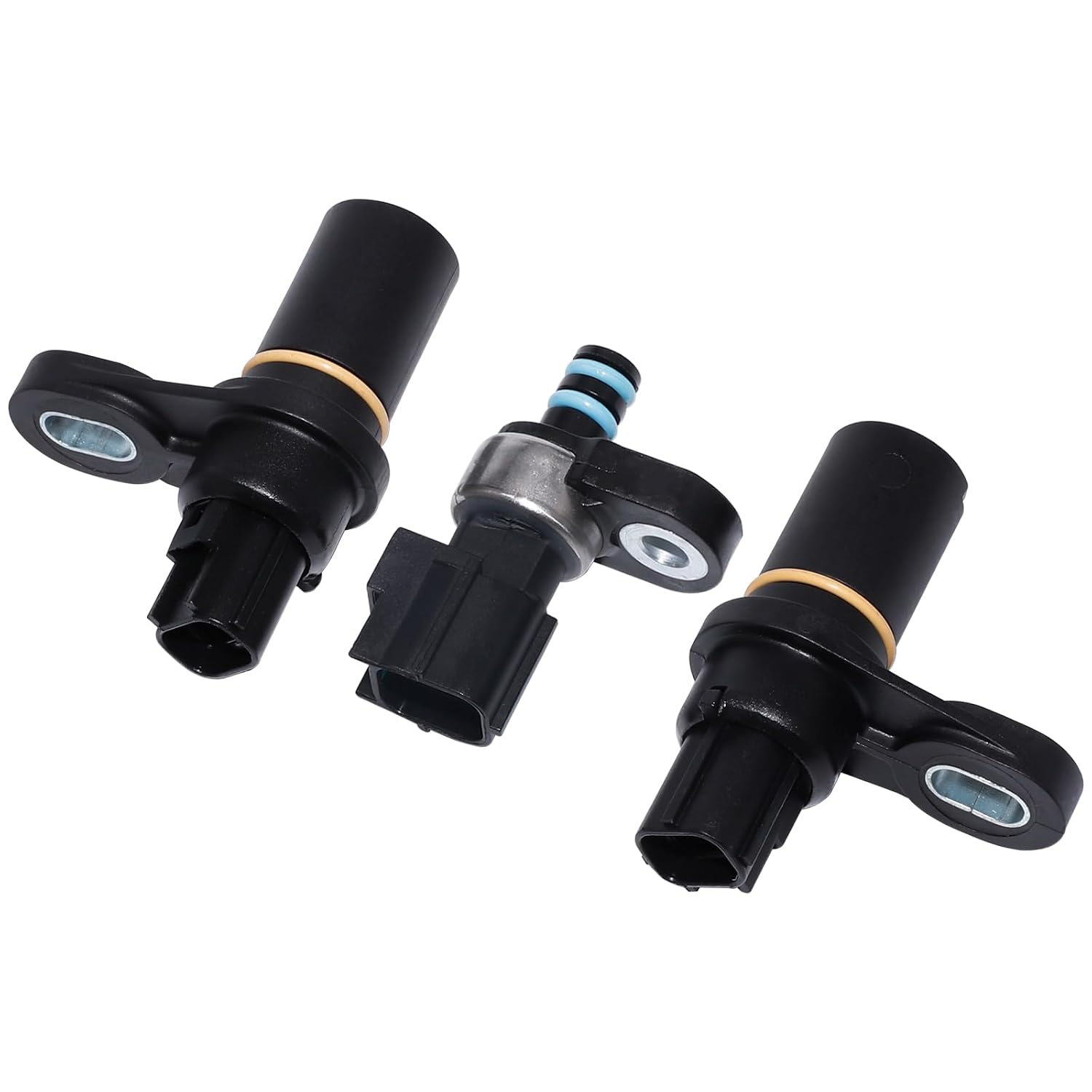
Chrysler's service information describes the input and output speed sensors as two-wire magnetic pickup devices that generate an AC signal as rotation occurs. Both are mounted in the left side of the transmission case, and both are primary inputs to the transmission controller. There is no Hall-effect electronics inside them, no power feed and no reference voltage. A magnet and a coil sit next to a toothed target, and the passing teeth induce a voltage.
- Input speed sensor reads the teeth on the input clutch hub. Chrysler's diagnostic text puts the count at 60 teeth. The controller turns that into input shaft (turbine) rpm.
- Output speed sensor reads the park gear, which has 30 teeth. That becomes output shaft rpm.
Chrysler lists what the controller does with those two numbers: it calculates the transmission gear ratio, detects speed ratio errors, and calculates the clutch volume index (CVI) for each friction element. It also compares input speed to engine speed to judge torque converter clutch slip and converter speed ratio. That list explains every symptom below. The sensors are not just a speedometer feed; they are the controller's only way of knowing what gear the transmission is really in.
To use the data you have to know the ratios. Chrysler's 45RFE/545RFE description lists 1st 3.00:1, 2nd 1.67:1, 2nd prime 1.50:1, 3rd 1.00:1, 4th 0.75:1 and reverse 3.00:1. The 545RFE adds a 0.67:1 fifth. Divide input rpm by output rpm on the scan tool and you should land on one of those numbers whenever the transmission is not in the middle of a shift.
Symptoms of a Failing 45RFE Speed Sensor
Because the controller learns clutch fill volumes from how long a ratio change takes, a noisy or dropping signal corrupts shift timing as well as gear detection. ATSG's 45RFE manual makes the point directly: defective input or output speed sensors, wiring and poor connections can cause the same out-of-range CVI readings as broken return springs or excessive clutch clearance. In the truck, that shows up as:
- Erratic shift quality that changes from day to day, including flares, tie-ups and harsh engagements that do not match any one clutch.
- A sudden drop into a default gear with the check engine light, often clearing after a key cycle. On a 45RFE the relay-off default is 3rd in Drive; our 45RFE limp mode guide explains the shutdown levels.
- Converter clutch that will not apply, or cycles in and out, because the input signal no longer matches engine speed.
- Gear ratio codes (P0731 through P0736) with no matching mechanical complaint.
- CVIs that swing wildly between drives instead of settling.
A dead speedometer is not a reliable sensor symptom on these trucks. Chrysler's service information for the same platform carries separate vehicle speed and wheel speed sensor codes, so check what each module reports before you assume the transmission sensor is the source.
The Codes and What Sets Them
Chrysler's theory of operation for the RFE speed sensor codes is short and worth knowing word for word, because it tells you which code belongs to which failure:
- P0715 Input Speed Sensor (flash code 56 on early trucks) sets on an excessive change in input rpm in any gear, meaning the signal went intermittent.
- P0720 Output Speed Sensor (code 57) sets on an excessive change in output rpm in any gear.
- P1794 Speed Sensor Ground (code 58) sets after a controller reset in neutral when the controller sees an input-to-output ratio of 1 to 2.
- P0731 to P0736 gear ratio errors set when the ratio of input to output rpm does not match the commanded gear once it is in that gear.
Chrysler notes that each of these can take up to five minutes of problem identification before the MIL comes on, which is why a truck can shift badly for a while before a code shows.
The P1794 logic is the clever one. Both sensors share one ground circuit back to the controller. If that common ground opens, Chrysler says both sensor inputs read the signal from the input sensor at a stop in neutral. Because the input target has 60 teeth and the output target has 30, the controller sees output speed as twice input speed, an apparent 1:2 ratio that cannot exist. If you see output rpm reading double input rpm with the truck parked in neutral, stop looking at sensors and go find the ground.
Scan Tool Checks Before You Touch a Wrench
Start with Chrysler's 45RFE/545RFE pre-diagnostic routine, which applies to every one of these codes: check pinion factor (tire size programming) where equipped, check fluid level, confirm the battery is fully charged, clear any engine codes first, and read and record all stored, active and pending transmission codes plus the DTC event data. Chrysler warns that a battery disconnect clears the event data and resets every learned transmission value to default, so do not unplug anything until you have written it down. The event data tells you the gear, speed and temperature the code set at.
Then watch the two speeds live:
- Park or Neutral at idle. Input rpm should track close to engine idle and output should read zero. Output reading about twice input points at the shared ground (P1794 territory).
- Steady cruise in each gear. Calculate input divided by output. A clean 1.67, 1.00 or 0.75 with a stable trace means the sensors are reporting honestly. If the ratio is right but the speeds jump to zero and back, you have an intermittent signal. If the ratio is steady but wrong for the commanded gear, the sensors are probably telling the truth about a slipping clutch.
- Wiggle test. With the engine running and a steady reading on the tool, flex the harness at the sensor connectors and along the left side of the case. A dropout while you move the harness is your answer.
The last point in step 2 matters more than anything else in this article. Chrysler's P0731 cause list includes the input speed sensor and its wiring, but most of the list is hydraulic: a cut underdrive piston seal, low fluid, a cracked or misinstalled primary filter, a sticking main regulator valve, a failed overrunning clutch, broken accumulator parts and low line pressure. Chrysler tells you to diagnose any solenoid, line pressure, speed sensor or loss-of-prime codes first. If the speed signals are clean and steady, a ratio code is a transmission problem, not a sensor problem.
Chrysler's Pinpoint Test
The P0715 and P0720 procedures follow the same pattern. Step one confirms the fault is current: for P0715, Chrysler asks whether input speed is below 400 rpm when it should not be; for P0720, it has you support the vehicle with the drive wheels off the ground and check whether output speed is below 100 rpm. Step two pulls the starter relay from the PDC (Chrysler's warning is that the vehicle can start in gear otherwise) and uses the diagnostic setup to check that the controller reads 3000 rpm input and 1000 rpm output, within 50 rpm. If the controller reads the known signal correctly, the wiring and controller are good and Chrysler's instruction is to replace the sensor.
If it does not, the procedure moves to the harness, with the sensor, solenoid/TRS and line pressure sensor connectors unplugged and Miller breakout tool 8815 installed so you never probe the controller terminals directly:
- Signal circuit (T52 input, T14 output) and the shared T13 ground: more than 0.5 volts is a short to voltage.
- More than 5.0 ohms end to end is an open.
- Less than 5.0 ohms to ground is a short to ground.
- If everything passes, Chrysler sends you to the controller terminals for corrosion, damage or push-out before condemning the controller, and after a controller replacement you run Quick Learn.
Testing the Sensor on the Bench
These are variable reluctance sensors, and Sean Boyle's GEARS Magazine series on speed sensors explains the tradeoff: they build their signal from magnetic flux collapsing and expanding as teeth pass, so output is weak at low speed and they are sensitive to electrical noise. Resistance varies widely by application, anywhere from about 500 to 2400 ohms across the industry, so the only meaningful comparison is to the spec or a known-good part. For the RFE family, ATSG's 68RFE manual, which uses the same sensor design, says both speed sensors are the same and interchange, and new sensors read 535 ohms at room temperature.
A reading near that with no short to the sensor body is a good start but not proof. A coil can pass on the meter and still drop out hot. The better test is an AC voltage or scope check while the target turns: the amplitude should rise with speed and the waveform should be even. A flat spot every revolution points at a damaged tooth on the target, not the sensor. Also look at the tip. The magnet collects clutch and gear debris, and a fuzzy tip weakens the signal.
When the Signal Problem Is Mechanical
The input sensor is only as good as the input clutch hub it reads. If the hub teeth are damaged, or the input clutch assembly is not fully seated, the signal suffers no matter how many sensors you install. ATSG's 45RFE assembly procedure actually uses the input speed sensor hole as the inspection port to confirm the input clutch assembly is fully seated before the pump goes on.
GEARS Magazine's "The Disappearing Input Speed Sensor Signal" is a Ford case, not a Chrysler one, but the lesson carries over: the input signal dropped to zero in two specific gears because a missing snap ring let the reluctor wheel stop turning when a clutch applied. The sensor was fine. When the signal vanishes only in certain gears, think about what is happening to the target in those gears.
Replacing a 45RFE Speed Sensor
Both sensors come out of the left side of the case with the transmission in the truck. Each is held by one bolt and sealed with an O-ring.
- Disconnect the battery only after you have recorded the DTC event data.
- Clean around the sensor before you pull it so dirt does not fall into the case.
- Unplug the connector, remove the bolt and pull the sensor. Expect a little fluid.
- Inspect the tip for debris and the bore for damage. Look at the old connector terminals; a green or spread terminal is often the real failure.
- Install a new O-ring lubricated with ATF+4 and torque the bolt to 105 in-lb (12 Nm), the figure ATSG lists for both sensor bolts.
- Top off the fluid to the correct hot level and run Chrysler's 45RFE/545RFE transmission verification test.
A replacement sensor does not require a Quick Learn by itself, but CVIs learned while a sensor was failing can be wrong. If shift quality is still off after the repair, let the controller relearn through normal driving or run the drive learn; our 45RFE harsh shift guide covers CVI ranges and the learn procedures.
Speed sensor for the RFE family
The two-wire input/output speed sensor used across the RFE line. Match the part number on your old sensor before you order.
View the RFE speed sensor at Core Transmission Parts →Shop RFE transmission parts →
Frequently Asked Questions
What are the symptoms of a bad 45RFE input speed sensor?
Erratic or harsh shifts, flares, a converter clutch that will not stay applied, and sudden drops into a default gear are the usual complaints, often with P0715 or a gear ratio code. Because the controller uses the input signal to learn clutch fill volumes, a failing sensor can also leave the CVIs swinging from drive to drive. Confirm it on the scan tool by watching input rpm for dropouts at steady speed.
Where are the speed sensors on a 45RFE?
Chrysler places both the input and output speed sensors in the left side of the transmission case. The input sensor reads the teeth on the input clutch hub and the output sensor reads the park gear. Each is held by one bolt and sealed with an O-ring, and both can be replaced with the transmission in the vehicle.
Are the 45RFE input and output speed sensors the same part?
In the RFE family they are the same design. ATSG's 68RFE manual says both speed sensors are the same and will interchange, and a new sensor reads about 535 ohms at room temperature. Still match the part number on the sensor you remove before ordering.
What does P1794 mean on a 45RFE?
P1794 is a speed sensor ground error. Both sensors share one ground circuit, and Chrysler says that if it opens, both inputs read the input sensor signal at a stop in neutral. With 60 teeth on the input target and 30 on the output target, the controller sees output speed at twice input speed and sets the code. Repair the shared ground circuit rather than replacing sensors.
Sources
- Chrysler — 45RFE/545RFE service information: Input and Output Speed Sensor Description and Operation, and Transmission Description (2007 Jeep Commander service manual). Backs the two-wire magnetic pickup design, the left-side case location, the input clutch hub and park gear targets, the controller's uses of the signals (gear ratio, speed ratio error, CVI, converter clutch slip), and the 3.00/1.67/1.50/1.00/0.75/0.67 and 3.00 reverse ratios. Description, Operation, Transmission description
- Chrysler — 45RFE/545RFE diagnostic procedures P0715 Input Speed Sensor, P0720 Output Speed Sensor and P1794 Speed Sensor Ground. Backs the set conditions, the five-minute MIL delay, the 60-tooth and 30-tooth targets and the 1:2 lost-ground ratio, the 400 rpm and 100 rpm current-fault checks, the starter relay step and 3000/1000 rpm within 50 rpm check, circuits T52/T14/T13, Miller tool 8815 and the 0.5 volt and 5.0 ohm limits. P0715, P0720, P1794
- Chrysler — P0731 Gear Ratio Error in 1st and the 45RFE/545RFE Pre-Diagnostic Troubleshooting Procedure. Backs the ratio code set condition, the mostly hydraulic cause list that also includes the input speed sensor and wiring, clearing related codes first, pinion factor, DTC event data, and the warning that a battery disconnect clears event data and learned values. P0731, Pre-diagnostic procedure
- ATSG (Automatic Transmission Service Group) — Dodge Ram 68RFE technical manual (preview). Backs the RFE speed sensors being identical and interchangeable, the 535-ohm room temperature reading for a new sensor, and the input clutch housing and parking gear targets. atsg.biz (PDF)
- GEARS Magazine (ATRA) — "Advanced Speed Sensors, Part 1" by Sean Boyle. Backs how variable reluctance sensors generate their signal, their weak low-speed output and noise sensitivity, the roughly 500 to 2400 ohm resistance range across applications, and AC voltage and scope testing. gearsmagazine.com
- GEARS Magazine (ATRA) — "The Disappearing Input Speed Sensor Signal." Backs the case of an input signal dropping to zero in specific gears because a missing snap ring let the reluctor stop turning, with the sensor itself good. gearsmagazine.com