A 68RFE that throws a speed sensor code usually comes in one of two ways. Either the truck suddenly drops into fourth gear with the check engine light on and a P0715 through P0723 stored, or it sets P0716 alongside a string of ratio and pressure codes and the owner has already bought a pair of sensors online. The first case is often a $30 part or a chafed wire. The second case can be a transmission that is coming apart inside, and new sensors will not fix it.
This guide walks through what the two speed sensors actually read, what the TCM does with those signals, how to tell a bad sensor from a bad circuit from a mechanical failure, and the 2024 Ram bulletins that list P0716 as a symptom of a cracked thrust bearing. If you are not sure which RFE unit is in the truck, start with our 68RFE identification guide.
What the Two Speed Sensors Read
The 68RFE uses two speed sensors, both on the left side of the case. Per ATSG's 68RFE technical manual, the input speed sensor reads a tone wheel on the input clutch housing, and the output speed sensor reads the teeth of the parking gear. Both are magnetic pickups: as the teeth pass the coil, the sensor generates an AC voltage, and the TCM counts the pulses as shaft rpm. They are two-wire sensors on twisted-pair wiring, with no power feed, so there is no reference voltage to check the way you would on a Hall-effect sensor.
ATSG also notes the two sensors are the same part and interchange, and a new sensor reads about 535 ohms at room temperature. That interchangeability is useful on the bench: if one position is suspect, swapping the sensors and seeing whether the code follows is a legitimate test.
On the 6.7L Cummins trucks the transmission is run by a standalone TCM in the New Generation Controller, not by the engine PCM. ATSG lists four jobs the TCM does with the input and output signals:
- Gear ratio — confirming the transmission is actually in the gear it commanded.
- Speed ratio error detection — the logic behind the incorrect-ratio codes.
- Clutch Volume Index — the adaptive fill-volume numbers that set shift timing.
- Torque converter clutch slip — input speed against engine speed.
That list explains why one bad sensor signal can make a 68RFE act like it has three different problems. A noisy input signal corrupts the ratio check, the adaptive learning and the TCC slip calculation all at once.
Symptoms of a Failing 68RFE Speed Sensor
When the TCM decides a fault could damage the transmission, it shuts off the transmission control relay and the unit falls back to hydraulic default. According to ATSG, that limp-in mode gives you fourth gear in Drive, and second gear if the lever is moved to 2 or L. Trucks with Electronic Range Select do not get second-gear limp-in, because the lever has no 2 or 1 position. So the classic complaint is:
- Truck takes off hard or sluggish in what feels like a high gear, stuck in fourth, check engine light on.
- Harsh or flared shifts before the code sets, because the ratio and adaptive math is working from a bad signal.
- Converter clutch that cycles or will not lock, since the slip calculation uses input speed.
- Intermittent faults that clear after a key cycle and come back on a rough road or in rain, which points at wiring or the connector rather than the sensor coil.
The codes you will see on a 68RFE are P0715 through P0718 for the input sensor (circuit, range/performance, no signal, intermittent) and P0720 through P0723 for the output sensor in the same order, per the TRNW 68RFE code list. A "no signal" code with no other codes present is the best-case scenario. A range/performance code stored with ratio codes is where you need to slow down.
Know the Ratios Before You Read the Data
Every speed sensor diagnosis on this unit comes back to one calculation: input rpm divided by output rpm should equal the gear ratio. ATSG's clutch application chart lists the 68RFE ratios as:
- 1st: 3.23:1
- 2nd: 1.83:1
- 3rd: 1.41:1
- 4th: 1.00:1
- 5th: 0.81:1
- 6th: 0.62:1
- Reverse: 4.44:1
So in third gear with 1,410 rpm on the input sensor, the output should read very close to 1,000 rpm. In sixth with 1,240 rpm input, output should be near 2,000 rpm. If the ratio is right and steady, both sensors are doing their job, whatever code is stored. If the output number drops to zero for an instant while the truck is rolling, or the ratio jumps around in a gear that is not shifting, you have a signal problem.
Step-by-Step Diagnosis
1. Pull every code and read them together
Write down every TCM and PCM code, including history codes, before you clear anything. A single P0717 or P0722 by itself is usually electrical. P0716 with ratio codes such as P0731 through P0735, pressure switch codes, P0868 or P0944 is a different conversation, covered below. Low fluid can also cause erratic behavior, so check level hot with ATF+4 before going further; our 68RFE fluid type and capacity guide has the procedure.
2. Watch input and output speed on a road test
Graph input speed, output speed and engine rpm together on a capable scan tool. You are looking for dropouts, spikes and a ratio that does not match the gear. Also compare input speed to engine rpm with the converter locked: they should match. Upshifts into fifth and sixth are normally delayed when fluid is below 40 F or above 240 F per ATSG, so do not mistake a cold-morning shift schedule for a sensor fault.
3. Check the sensor and connector at the case
Unplug the sensor and measure across its two terminals. ATSG gives about 535 ohms for a new sensor at room temperature; an open or a reading near zero condemns it. Pull the sensor and look at the tip. Magnetic pickups collect fine metal, and a tip coated in fuzz can weaken the signal. A tip coated in heavy metal or brass is not a sensor problem, it is a transmission problem announcing itself. Check the O-ring for leaks and the connector for green corrosion or a spread terminal.
4. Check the harness
Because these are two-wire AC generators, a chafed wire or a short to ground produces the same "no signal" result as a dead coil. Check each circuit for continuity from the sensor connector back to the TCM, and for a short to ground and between the two wires. On a road test failure, wiggle-test the harness where it runs along the transmission and crossmember while watching the live data. If you have a scope, back-probe the signal: a healthy sensor makes a clean sine wave whose amplitude and frequency rise with speed. Missing or flattened cycles point at the tone wheel or the gap, not the wiring.
If input and output codes set together, check the ground before you buy two sensors. On the RFE family both speed sensors return through one shared ground circuit. Chrysler's 45RFE/545RFE procedure for P1794 Speed Sensor Ground explains the tell: with that common ground open, both inputs read the input sensor signal, so at a stop in neutral the controller sees output speed at twice input speed and sets the code. Chrysler's pinpoint tests for the speed sensor circuits use the same limits on every wire: more than 0.5 volts is a short to voltage, more than 5.0 ohms end to end is an open, and less than 5.0 ohms to ground is a short to ground (Chrysler P1794 procedure). Our 45RFE speed sensor guide walks through the full Chrysler procedure.
5. Swap the sensors
Since both positions use the same part, swapping input and output sensors is a cheap confirmation. If the code moves from input to output, the sensor is bad. If it stays with the position, the problem is the harness, the tone wheel or the parts inside.
When P0716 Is Not the Sensor: The 2024 Thrust Bearing Bulletins
This is the one that costs people money. FCA TSB 21-054-24 (October 26, 2024) and its later revision, TSB 21-012-25 Rev. B (February 21, 2025, also issued as Rapid Service Update 25-018), cover 2024 Ram 2500 and 3500 pickups with the 6.7L Cummins and 68RFE. Rev. B applies to trucks built from June 14, 2024 through September 4, 2024. The listed cause is rear selective thrust bearing cracking.
The code list in those bulletins is the tell. It includes P0716 Input Speed Sensor 1 Circuit Performance right next to P0218 high-temperature operation, P0729 and P0731 through P0735 incorrect-ratio codes, P0841, P0868, P0871, P0876 pressure codes and P0944 loss of pump prime, with complaints of hard shifts into gear and limp mode. The bulletin repair is not a sensor. It is a replacement 68RFE assembly (part K52109056AC), six converter bolts, ATF+4 top-off and a Quick Learn with wiTECH.
Our read from the bench: when a thrust surface fails, parts start moving that should not, debris goes through the unit, and the input sensor code is one of the first electrical symptoms of a mechanical event. That is why the rule in our shop is simple. If P0716 is stored with ratio or pressure codes, pull the pan before you order sensors. Metal and brass in the pan, or on the sensor tips, means the sensor code is a messenger. Our P0868 guide and limp mode guide cover the pressure side of that picture.
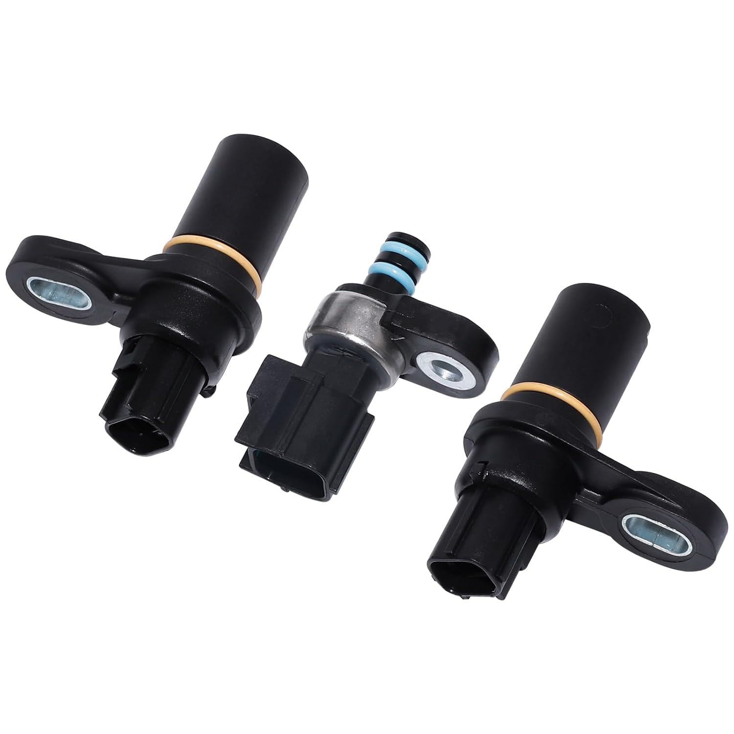
68RFE Input and Output Speed Sensor and Pressure Transducer Kit (OEM 72436)
Both speed sensors plus the line pressure transducer for 2007-2024 68RFE trucks. If the diagnosis points at the sensors, this replaces every external sensor on the case in one job.
View the 72436 sensor kit →After the Repair: Quick Learn or Not
Replacing a sensor does not change clutch clearances, so the adaptive values the TCM has learned are still valid once the signal is good. FCA's STAR case S2021000006 is a useful caution here: a Quick Learn clears all previously learned adaptives, and the 68RFE can take up to 2,500 miles to fully adapt again. FCA tells dealers not to run Quick Learn as a first step on shift-quality complaints without codes, and instead to run the 68RFE Drive Learn cycles that relearn specific clutch fill volumes. Where Quick Learn is required, as after the transmission replacement in TSB 21-012-25, run it, then drive the truck through a full range of shifts before handing it back.
Clear the codes, road test with the same data graph you used for diagnosis, and confirm the ratio is correct and steady in every gear before calling it fixed.
Shop 68RFE speed sensors →
The Short Version
- Both 68RFE speed sensors are the same two-wire magnetic pickup, about 535 ohms new; input reads the input clutch housing tone wheel, output reads the park gear.
- A sensor fault can put the truck in fourth-gear limp mode and upset shift adaptives and TCC control.
- Check that input divided by output matches the gear ratio: 3.23, 1.83, 1.41, 1.00, 0.81, 0.62.
- Test resistance, inspect the tip and O-ring, check the harness, then swap sensors to see if the code follows.
- P0716 stored with ratio or pressure codes, especially on a 2024 Ram, means pull the pan and check TSB 21-012-25 before buying sensors.
Frequently Asked Questions
What are the symptoms of a bad 68RFE speed sensor?
The most common symptom is the truck dropping into limp mode, which on a 68RFE means fourth gear in Drive, with the check engine light on and a P0715-P0723 code stored. Before the code sets you may notice harsh or flared shifts and a converter clutch that will not lock, because the TCM uses the sensor signals for ratio checks, adaptive learning and TCC slip.
Are the 68RFE input and output speed sensors the same?
Yes. Per ATSG, both sensors are the same part and interchange. A new sensor reads about 535 ohms at room temperature. That makes swapping them a quick test: if the code follows the sensor, the sensor is bad; if it stays with the position, look at the wiring or internal parts.
Where are the 68RFE speed sensors located?
Both are on the left side of the transmission case. The input sensor reads a tone wheel on the input clutch housing and the output sensor reads the parking gear teeth. Pull each one and inspect the tip and O-ring when you test it.
Can a 68RFE P0716 code mean internal damage?
Yes. FCA TSB 21-012-25 lists P0716 among the codes set by a cracked rear selective thrust bearing on 2024 Ram 2500 and 3500 trucks, alongside ratio, pressure and pump prime codes, and the repair is a replacement transmission. If P0716 appears with ratio or pressure codes, inspect the pan for metal before replacing sensors.
Do I need a Quick Learn after replacing a 68RFE speed sensor?
A sensor swap does not change clutch clearances, so it usually does not call for one. FCA notes a Quick Learn clears all learned adaptives and the 68RFE can take up to 2,500 miles to fully re-adapt. Clear codes and road test instead; run Quick Learn when service information calls for it, such as after a transmission replacement.
Sources
- ATSG (Automatic Transmission Service Group) — Dodge Ram Trucks 68RFE Transmission technical manual (preview). Backs the left-side location of both speed sensors, the input sensor reading the input clutch housing tone wheel and the output sensor reading the parking gear, the AC signal generation, the four TCM uses of the signals, sensor interchangeability and the 535-ohm new-sensor resistance, the standalone TCM in the NGC on 6.7L trucks, fourth-gear and second-gear limp-in and the ERS exception, the 40 F / 240 F fifth and sixth upshift delay, and the gear ratio chart. atsg.biz (PDF)
- FCA US LLC via NHTSA — TSB 21-012-25 Rev. B, "Rear Selective Thrust Washer Failure" (February 21, 2025; RSU 25-018). Backs the 2024 Ram 2500/3500 6.7L 68RFE build window, the DTC list including P0716, the rear selective thrust bearing cracking cause, and the transmission replacement, part K52109056AC and Quick Learn repair. static.nhtsa.gov (PDF)
- FCA US LLC via NHTSA — TSB 21-054-24, "Rear Selective Thrust Washer Failure" (October 26, 2024; RSU 24-149). Backs the original release of the bulletin and the same symptom and DTC list. static.nhtsa.gov (PDF)
- FCA US LLC via NHTSA — STAR case S2021000006 Rev. A, "Transmission Slip/Flare During Shifts With No DTCs Set. Manual Drive Learn Procedure." Backs Quick Learn clearing all adaptives, the up-to-2,500-mile adaptation period, and the instruction to use the 68RFE Drive Learn instead of Quick Learn as a first step. static.nhtsa.gov (PDF)
- TRNW (Transmission Rebuilders Network) — 68RFE diagnostic trouble code index. Backs the P0715-P0718 input and P0720-P0723 output speed sensor code definitions for the 68RFE. trnw.net
- Chrysler — 45RFE/545RFE diagnostic procedures P1794 Speed Sensor Ground and P0715 Input Speed Sensor (2007 Jeep Commander service manual). Backs the shared speed sensor ground circuit, the apparent 1:2 input-to-output ratio at a stop in neutral when it opens, and the 0.5 volt and 5.0 ohm circuit test limits. P1794, P0715