Most 700R4 lockup complaints that come across the counter are not converter complaints. They are control complaints. The clutch inside the converter is a simple on/off device on this unit (Sonnax classifies the 700-R4/4L60 as an on-off converter circuit with a TCC enable solenoid, the design the 4L60-E later replaced with an enable plus PWM solenoid), and whether it applies depends on a chain of parts that starts at a fuse and a brake switch, runs through the case connector, a solenoid, sometimes one or two pressure switches, a check ball in the pump cover, and finally a hydraulic signal that only exists once the transmission is in 2nd gear or higher. Break any link and the converter never locks, locks at the wrong time, or will not let go.
Below is the whole chain, the 1982-1993 changes, how swap wiring kits do it, and how to test each piece. For a vibration once it does lock, see our 700R4 shudder diagnosis guide.


The Hydraulic Side: What the Solenoid Actually Does
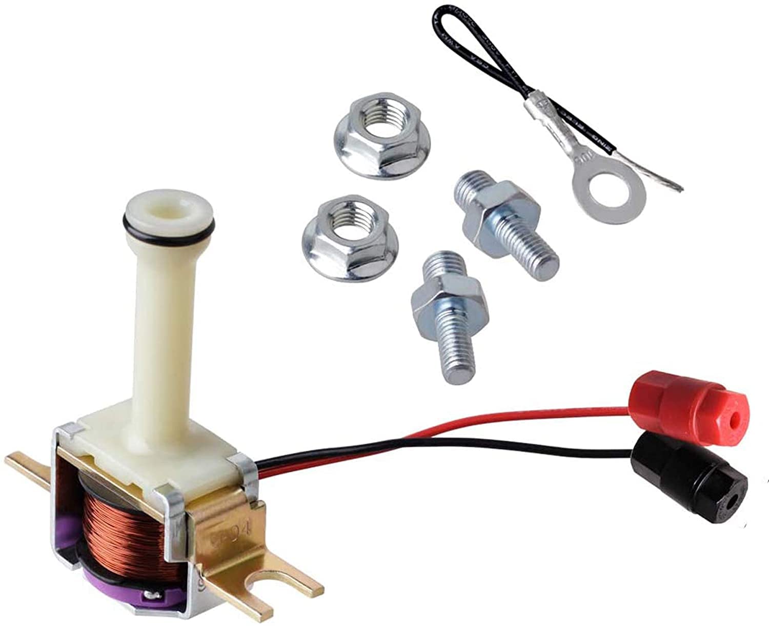
The 700R4 TCC solenoid is not the valve that applies the clutch. It is a pilot. The real work is done by the TCC apply valve, which lives in the pump cover, not the valve body. Signal oil reaches the end of that valve through an orifice. With the solenoid off, its check ball is unseated and the signal oil bleeds to exhaust, so the apply valve stays in release. When the solenoid is energized, the coil seats the ball, the exhaust closes, signal pressure builds, and the apply valve strokes.
Where does that signal oil come from? On the later valve bodies it is 2nd clutch oil. ATSG's THM 700-R4 Update Handbook documents the November 15, 1989 change in which the TCC bore was removed from the valve body and a notch in the worm track was added that “allows 2nd clutch oil into the TCC signal circuit.” On those units the oil the solenoid controls does not exist until the 1-2 shift, so the converter physically cannot lock in 1st no matter what the electrical side is doing.
Once the apply valve strokes, the converter side follows the logic Sonnax lays out in its “Troubleshooting Lockup Issues” article. Release oil normally flows out through the turbine shaft, between the piston and cover, and on to the cooler. When the apply valve moves, that flow reverses, the input shaft passage opens to exhaust, and the piston is pushed into the cover. Sonnax makes the point that a full converter will begin to apply as soon as release oil is opened to exhaust, even before apply oil arrives.
The Electrical Side: How Lockup Was Commanded From the Factory
On a stock computer-controlled 700R4, the circuit is simple: switched 12 volts arrives at the case connector through the brake switch, passes through the solenoid coil, and the ECM provides the ground when its conditions are met. Step on the brake, the 12 volt feed opens, the solenoid de-energizes, and the converter releases. Check that feed and its fuse before the pan comes off.
What makes the 700R4 confusing is that GM changed the in-pan side of the circuit several times. The ATSG handbook lists 17 different internal harness and solenoid “wiring types” across 1982 to 1993, identified by the color of the plastic insulator on the solenoid and by the last four digits of the GM part number cast into it. Three changes matter most on the bench:
- June 28, 1987 — temperature switch added (some models). Per ATSG, a valve-body-mounted temperature switch (GM 8654421) was added as an alternate ground path for the solenoid. It applies the converter clutch when sump temperature reaches 125-135°C (259-275°F) and the transmission is in 4th. These use the Type-15 harness (dark blue insulator, “4415”).
- May 10, 1988 — 4-3 pulse switch eliminated. The 4-3 pulse switch on the valve body momentarily released the converter during a 4-3 downshift. ATSG documents that this function was moved into the ECM for 1988, the switch was replaced with a pipe plug, and the Type-18 harness (GM 10478100, light brown insulator, “8100” cast in) was introduced. ATSG is explicit that the Type-18 harness must not be used on earlier models, because those ECMs are not programmed to do the pulse-switch job.
- November 15, 1989 — converter clutch valve train removed. Earlier non-ECM applications used a converter clutch shift valve and converter clutch throttle valve in the valve body to decide when to lock. ATSG notes that from 1989 production all models became ECM-controlled TCC apply, and that the new valve body cannot be used on earlier models that were not ECM controlled.
The rule: match the valve body and internal harness to the vehicle's control strategy, not just to the transmission.
The pressure switches, and which ones are not for lockup
The valve body carries pressure switches threaded into its passages, and the case may carry external ones. Not all of them have anything to do with lockup. ATSG lists an external normally open 3rd clutch switch (GM 14036254) on some four-cylinder applications that closes at 42 psi; it cycles the A/C compressor off during a forced downshift. ATSG also lists 1984-only California 4WD truck switches in the external 4th pressure tap, one normally open that closes at 26 psi (diesel) and one normally closed that opens at 26 psi (gas), used to control EGR bleed.
The switch that matters on a swap is the 4th clutch pressure switch on the valve body. On a non-computer conversion it becomes the ground path that limits lockup to overdrive.
Lockup on a Carbureted Swap: How the Wiring Kits Do It
Drop a 700R4 behind a carbureted engine with no ECM and the converter will never lock, because nothing grounds the solenoid. B&M's converter instructions say the same thing plainly: in a vehicle that was not originally equipped with a lockup transmission, the TCC will not operate and the converter acts as a non-lockup unit until the circuit is wired. That is the most common “no lockup” call on older hot rods and square-body swaps; it is a wiring omission, not a failure.
TCI's 376600 instruction sheet shows the standard way to do it. The kit supplies a new internal harness, a two-terminal normally open 4th gear pressure switch, and a vacuum switch. The pressure switch is installed in the valve body at 8 ft-lb, the solenoid bolts get 8 ft-lb, and switched 12 volts (18-gauge) goes to terminal A at the case connector. With the vacuum switch on ported vacuum, TCI states the converter engages automatically in 4th gear only when engine vacuum is above 8-10 in-Hg, and releases on a downshift out of 4th or when vacuum drops under throttle. For release on braking, TCI calls for an OEM normally closed brake switch in the 12 volt feed.
Three details from that sheet save a lot of grief:
- One-wire solenoids will not work. All the switching in this design is on the ground side, so the solenoid must be a two-wire unit. TCI points to GM 8654126 as the correct replacement.
- The kit does not talk to the ECM. TCI warns not to plug the factory computer harness into a transmission converted this way. The ECM keeps running the engine but no longer controls lockup.
- The optional green wire is a ground. It can run to a dash toggle to force lockup manually in 2nd, 3rd or 4th, but TCI warns that putting 12 volts on it can short the solenoid.
Testing the Circuit, Start to Finish
Work from the outside in.
- Feed side. Key on, engine off, back-probe terminal A at the case connector. You should have battery voltage with your foot off the brake and none with the pedal down. No voltage at all: fuse, brake switch, or the feed wire. Voltage that stays with the pedal down: brake switch adjustment.
- Coil resistance from outside the case. Disconnect the feed and measure across the circuit at the case connector. TCI's spec for a good solenoid is 24.5 to 26.5 ohms. A reading of zero means a short inside the pan.
- Ground side command. On an ECM-controlled unit, put a test light or voltmeter on the ground terminal and road-test. At cruise in a gear where lockup should occur, the ground should be pulled low and the engine RPM should drop a couple of hundred as the clutch applies. No ground command means an ECM input problem (vehicle speed, coolant temperature, throttle position), not a transmission problem.
- Solenoid on the bench. With the solenoid out, TCI's mechanical test is simple: with no power you should be able to blow air through it. Apply 12 volts and ground, and the coil should seat the ball and stop the air. Check the end O-ring too.
- Snout and pump side. If the coil checks good, the command is present, and it still will not lock, the oil is leaking somewhere between the solenoid and the apply valve. Sonnax's 77942-01K snout kit listing describes the OE plastic snout cracking where it contacts the plunger valve and leaking oil that should go to the converter clutch apply valve.
If you have a cooler flow meter, Sonnax gives a clean confirmation test: when lockup is commanded, cooler flow should drop momentarily and then settle. No change means the apply valve never moved. Next, Sonnax blocks the TCC control valve in apply: if the engine stalls in gear, the converter clutch holds and the fault is in the control circuit.
700R4 TCC Lock-Up Solenoid with Harness, OEM 10478100
The Type-18 solenoid and internal harness ATSG lists for 1988-and-later ECM applications with the 4-3 pulse switch eliminated. Confirm your wiring type by the insulator color before ordering.
See the harness at Core Transmission Parts →Different wiring type? Browse all 700R4 parts.
When It Locks Too Early, or Will Not Let Go
Lockup right after the 1-2 shift, or a converter that stays applied and stalls the engine at a stop, has two usual causes.
The first is the solenoid itself. Sonnax's lockup article describes a 200-4R, which shares this control design, that locked up immediately after the 1-2 shift and only released in 1st. The cause was a defective solenoid; because the signal oil on that unit is also 2nd clutch oil, a solenoid that will not exhaust applies the converter the moment 2nd gear comes in.
The second is the pump. Sonnax's 77805-K TCC apply valve kit listing covers the 200-4R, 4L60 and non-PWM 4L60-E and lists the symptoms: no lockup, falls out of lockup when hot, lockup immediately after 2nd gear, and fluid blown out the fill tube. The cause is bore wear in the pump cover. Signal oil leaks past the spool so the valve will not stroke when hot, and converter feed oil leaks past the same clearance and joins the signal oil, more than the solenoid can exhaust, so the valve strokes on its own. Sonnax's lockup article adds that if release flow drops below 0.45 gpm, the piston starts to drag on the cover.
Before you install the Sonnax valve, count the spools on the OE valve. Sonnax states that non-PWM valves (what a 700R4 uses) have double spools, PWM valves have a single spool and need 77805E-K, and that mismatching the two causes rapid converter failure. Do not go by valve material; some early PWM pumps used steel valves.
700R4 TCC solenoids, lockup wiring kits, pumps, valve bodies and rebuild kits, shipped fast from the USA.
Shop 700R4 parts →FAQ
When is a 700R4 torque converter supposed to lock up?
On a stock computer-controlled 700R4, the ECM grounds the TCC solenoid at steady cruise once the transmission is in 2nd gear or higher and its own conditions are met, and the brake switch releases it. On a conversion using a kit like the TCI 376600, lockup happens in 4th gear only, when engine vacuum is above 8-10 in-Hg, and releases on a downshift out of 4th or when vacuum drops under throttle.
Does a 700R4 need a computer to lock up?
No. Without an ECM, nothing grounds the solenoid, so the converter never locks. A wiring kit adds 12 volts to terminal A and routes the solenoid ground through a normally open 4th gear pressure switch and a vacuum switch, so the transmission controls lockup on its own.
How do I test a 700R4 TCC solenoid?
Measure resistance across the circuit at the case connector or across the solenoid itself; TCI specifies 24.5 to 26.5 ohms for a good unit, and zero means a short. Then air-test it: with no power, air should pass through; with 12 volts and ground applied, the ball should seat and stop the air. Inspect the O-ring and the snout for cracks while it is out.
Why does my 700R4 lock up right after the 1-2 shift?
The two usual causes are a solenoid that will not exhaust and a worn TCC apply valve bore in the pump cover. Because the signal oil comes from 2nd clutch oil, a stuck solenoid applies the converter the moment 2nd comes in. Bore wear lets converter feed oil leak into the signal circuit and stroke the valve on its own; Sonnax's 77805-K valve kit repairs that bore on non-PWM units.
Can I swap a 700R4 internal harness or valve body between years?
Not freely. ATSG warns that the 1988-and-later Type-18 harness, with the 4-3 pulse switch eliminated, must not go in earlier models whose ECM does not handle the pulse-switch function, and that the November 1989 valve body without the TCC bore cannot be used on earlier non-ECM-controlled models. Identify the wiring type by the solenoid insulator color first.
Sources
- ATSG — THM 700-R4 “Update Handbook” (Automatic Transmission Service Group, 2003). Backs the June 28, 1987 temperature switch (GM 8654421) applying the converter clutch at 125-135°C in 4th and the Type-15 harness; the May 10, 1988 elimination of the 4-3 pulse switch, its function moving to the ECM, the Type-18 harness (GM 10478100) and the warning against using it on earlier models; the November 15, 1989 removal of the TCC bore with 2nd clutch oil feeding the TCC signal circuit and all models becoming ECM-controlled; the 17 wiring types identified by insulator color; and the 3rd clutch (42 psi) and 1984 California 4th clutch (26 psi) external switches. ATSG handbook (PDF)
- Sonnax — “Troubleshooting Lockup Issues,” Sonnax TASC Force. Backs the release and apply oil flow description, that a full converter begins to apply once release oil is exhausted, the cooler-flow drop when lockup is commanded, the blocked TCC control valve stall test, the 0.45 gpm release-flow threshold below which the piston drags, and the 200-4R example of lockup right after the 1-2 shift from a defective solenoid. sonnax.com
- Sonnax — TCC Apply Valve Kit 77805-K (GM 200-4R, 4L60, non-PWM 4L60-E). Backs the pump bore wear cause and symptoms (no lockup, falls out of lockup when hot, lockup immediately after 2nd, fluid out the fill tube), double-spool versus single-spool identification, the PWM kit 77805E-K, and the warning that mismatched valves cause rapid converter failure. sonnax.com
- Sonnax — TCC Solenoid Snout Kit 77942-01K (GM 4L60/700-R4, ’96-earlier 4L60-E). Backs the cracked OE plastic snout leaking oil meant for the converter clutch apply valve, and the listed symptoms of TCC apply concerns, overheated converter and loss of lube. sonnax.com
- TCI Automotive — 376600 Universal TCC Lock-Up Kit instructions (700R4 and 200-4R). Backs the normally open 4th gear pressure switch and 8 ft-lb torque on the switch and solenoid bolts, 12 volts to terminal A, lockup in 4th above 8-10 in-Hg vacuum, the normally closed brake switch option, the two-wire solenoid requirement and GM 8654126, the ECM incompatibility warning, the green ground-side override, and the 24.5-26.5 ohm resistance and air-flow solenoid tests. TCI instructions (PDF)
- Sonnax — Maura Stafford, “GM TCC Circuits” (September 2005). Backs the classification of the 700-R4/4L60 as an on-off converter clutch circuit using a TCC enable solenoid, and its transition to the enable-plus-PWM solenoid design in the 4L60-E. sonnax.com
- B&M (Holley) — GM lockup torque converter installation instructions, 70420. Backs that a lockup converter installed in a vehicle not originally equipped with a lockup transmission will not apply its TCC and runs as a non-lockup converter, and that the TCC in a TH700-R4, 4L60, TH200-4R or TH350C can be made to operate with added wiring. B&M instructions (PDF)