Nearly every 10L80 speed sensor job that goes sideways goes sideways in the same place: the tech pulls up scan data, sees a speed PID sitting flat at zero while the truck is rolling, and orders a sensor. On this transmission that zero is often the correct reading. Two of the four speed sensors are supposed to read nothing through the lower gears, and knowing which two is the difference between a fifteen minute diagnosis and a valve body coming out for no reason.
This is the GM half of the Ford and GM joint 10-speed. The mechanical side carries over from the 10R80 almost exactly, and most of the published tech on these sensors is written against the Ford unit. That is usable here, with one caution I will come back to: connector pin identification differs between the Ford and GM versions, so borrow the theory and the ratios, not the pinout.
Four sensors, not two
The 10L80 has four internally mounted two-wire Hall-effect speed sensors. Per Mike Souza's teardown of the shared 10-speed for Transmission Digest, the TCM sends a 9-volt supply to all four, and each sensor returns a DC square wave whose frequency rises with reluctor speed. The TCM uses those four rpm values to set line pressure, pick shift timing, verify gear ratio and calculate converter clutch slip.
What each one actually watches:
| Sensor | Also called | What it reads | Range/performance code |
|---|---|---|---|
| Input / turbine | ISS, TSS | 40 magnets bonded in rubber, riveted to the input (No. 2) planet carrier splined to the turbine shaft | P0716 |
| Intermediate A | ISS1, ISSA | 50-tooth steel reluctor welded to the reaction carrier ring gear and 1-2-3-4-5-6 reverse brake clutch hub | P0792 |
| Intermediate B | ISS2, ISSB | 50-tooth steel reluctor pressed onto the non-ferrous transfer shell | P2746 |
| Output | OSS | 68-tooth steel reluctor riveted to the output (No. 4) planet carrier | P0721 |
The input sensor is the odd one out. It is the only one of the four with no magnetic pickup in the tip, because the magnets live in the reluctor ring itself and it reads them straight through the wall of the non-ferrous transfer shell. That shows up on the meter: Souza measured the input sensor at roughly 346.7 kilohms against about 4.88 milliohms for the other three. If you have four sensors loose on the bench and no labels, that one reading sorts the input sensor out of the pile in ten seconds.
The connector alignment tabs are keyed differently by color, so the sensors cannot be cross-connected once they are in their correct holes. They absolutely can be installed in the wrong holes, and then the harness reaches the wrong plug. That is how a clean rebuild comes back with ratio codes on the first road test.
Symptoms, sorted by which sensor quit
Input/turbine sensor. This is the loud one. Lose the turbine signal and the code sets essentially the moment a gear is selected, the MIL comes on and the unit sits in a commanded neutral state. The driver's complaint is "it revs and does not go," not "it shifts funny." The TCM has no way to compare turbine speed to output speed, so it will not commit a clutch.
Output sensor. This one is sneakier, because it is usually intermittent long before it is dead. The classic description, and the one in Transmission Digest's 2025 case study on a 10R80 with P0721, is that from a stop the truck occasionally feels like it is in neutral, then jerks and drops into limp. On scan data the output speed signal intermittently drops out during exactly those events. Speedometer and cruise behavior can get strange alongside it.
Intermediate A and B. These two rarely produce a clean standalone complaint. Per Ford's own strategy description, ISSA monitors the speed and rotational direction of ring gear 1 and ISSB monitors planetary carrier 1 and ring gear 4, and both exist to monitor clutch states for fault detection. So when one goes bad you typically get gear ratio codes and a shift quality complaint rather than a no-move. The ratio DTC set on this unit runs P0731 through P0735 for first through fifth, P0736 for reverse, P0729 for sixth, P076F for seventh, P07D9 for eighth, P07F6 for ninth and P07F7 for tenth.
Before you condemn anything: two PIDs read zero on purpose
This is the part that saves the most parts. Wayne Colonna laid out the per-gear behavior in Transmission Digest, and it is worth memorizing:
- ISSA reads 0 rpm in first through sixth gear. It watches the outer lugs on the No. 1 ring gear, which the A clutch holds stationary. That clutch does not release until seventh. ISSA only starts reporting rpm on the 6-7 shift.
- ISSB reads 0 rpm in first and second gear. It watches the sheet metal window on the clutch cylinder, lugged to the front P1 carrier, which the low one-way clutch holds in first and second. ISSB wakes up on the shift into third.
- TSS and OSS always report rpm while the vehicle is moving. TSS also shows rpm in Park and Neutral with the engine running; OSS reads zero sitting still.
So a 10L80 crawling through a parking lot in first gear with two speed PIDs pinned at zero is a healthy 10L80. Read that data at 5 mph without the chart in front of you and you will replace two good sensors.
The single best test on this unit falls straight out of that: hold seventh gear in manual mode. Seventh is direct drive, the whole gear train turns one to one, and all four sensors should read the same rpm. One PID low, ragged or flat in seventh isolates itself in one road test. Colonna also warns that these PIDs are not real time and lag slightly through a shift, which is exactly why you hold a gear manually instead of trying to read them on the fly.
Rule out the recall and the harness before the pan comes down
A 10L80 SUV that "drops out of gear" or "lost its top gears" may not have a sensor problem at all. GM's Part 573 filing for recall 26V085 (GM N252536750) covers 43,732 2022 Tahoe, Suburban, Yukon, Yukon XL, Escalade and Escalade ESV gas models with the 10-speed and electronic range select. GM says transmissions built April to September 2022 have unique internal hardware that may increase valve wear, and the remedy software limits the transmission to 5th gear when it detects that wear. GM also says all 2023 and later models were built with that software. Check recall status and look for a 5th-gear limit event before you read anything into the speed PIDs.
Then prove the wiring outside the case. Transmission Digest's August 2026 write-up on a GM 8L90 van with intermittent failsafe is a good reminder of how these go: the scan tool pointed at a supply circuit shorting to ground, and the cause was one wire rubbed through on a bolt tip along the harness route between the TCM and the transmission. A wiggle test of that whole run costs ten minutes. Dropping the pan to replace a sensor that was never bad costs a lot more.
Working on the Camaro or Cadillac version? The 10L90 speed sensor guide covers GM's published 10L90 ratios and the car-side recall, 25V-148.
Use the ratio math
Divide turbine speed by output speed and you have the ratio the transmission is actually delivering. Compare it to the commanded gear:
| Gear | Ratio | Gear | Ratio |
|---|---|---|---|
| 1st | 4.696 | 7th | 1.000 |
| 2nd | 2.985 | 8th | 0.854 |
| 3rd | 2.146 | 9th | 0.689 |
| 4th | 1.769 | 10th | 0.636 |
| 5th | 1.520 | Reverse | 4.866 |
| 6th | 1.275 | — | — |
If measured ratio matches the table in every gear but a sensor PID looks wrong, the sensor is reporting and the fault is elsewhere. If the ratio is wrong in a predictable pattern, work backward: which sensor feeds that comparison, and is it in the right hole? Sonnax documents two specific field conditions worth ruling out before you buy anything. With TSS and ISSA swapped, rpm shows up on ISSA in Park and Neutral with zero on TSS, which is backwards, and P0716 sets as soon as you select a gear. With OSS and ISSB swapped, the vehicle drives and shifts normally at first and then stacks up multiple gear ratio codes.
The scope test that separates a sensor from the hardware
Here is where these jobs get expensive. The sensor only reports what the reluctor hands it, and on this transmission the reluctors are riveted, welded and pressed to rotating planetary hardware.
Two documented failures make the point. Sonnax reports deteriorating P2 planet magnets, the ones the turbine sensor reads, producing a vehicle that drives 40 to 100 feet and then goes to neutral, with an incorrect first gear ratio showing just before the protection kicks in. They check those magnets with an ABS test strip. Separately, Transmission Digest's 2025 P0721 case documented a truck that kept dropping the output signal after a new output sensor and a valve body R and R. On the scope, the drive-direction signal showed large wide spikes where narrow pulses belonged, while the reverse signal stayed clean. These sensors read rotational direction as well as speed, and that asymmetry was the clue: the technician found pitting in two of the sixty windows of the output carrier, on one side only, so reverse rotation never crossed the damaged area. The fix was a carrier, not a sensor.
The bench setup used in that article is easy to copy: a test harness built from a 9-volt battery and 220-ohm resistors, which lets you power and scope a sensor off the vehicle at the same voltage the TCM supplies. If you scope in the truck instead, verify 9 volts at the sensor first. No supply voltage turns a sensor diagnosis into a wiring diagnosis, and that is a different job.
What it takes to get at them, and what it costs you in fluid
These sensors are internal. Getting to them means the pan comes down, the auxiliary fluid tube and seal come out, the internal harness gets unlocked and the valve body comes off. Leave the center valve body bolt in until last as an alignment pin. Units with auto stop-start have an auxiliary pump sitting over the output sensor that has to come off as well.
Plan the fluid before you start. Per GM's 2025 transmission capacities chart, every 10L80 application takes 7.7 liters (8.1 quarts) of DEXRON ULV on a fluid change. ULV is an ultra low viscosity spec, and GM lists DEXRON VI and DEXRON HP for the 6L and 8L units on that same chart. Do not top a 10L80 off with whatever is on the shelf.
The repair order that works
- Pull all codes, including gear ratio codes, and note which ones set together.
- Check fluid level and condition first. Aeration and low level produce ratio errors that look electrical.
- Record the four speed PIDs plus engine speed, gear commanded and gear ratio measured on a road test, in manual mode, one gear at a time.
- Check the two known-zero conditions against the list above before calling any PID dead.
- Hold seventh. All four should match.
- Verify 9 volts at the suspect sensor, then scope the signal.
- Only then decide: sensor, internal harness, or reluctor and carrier.
10L80 Output Speed Sensor
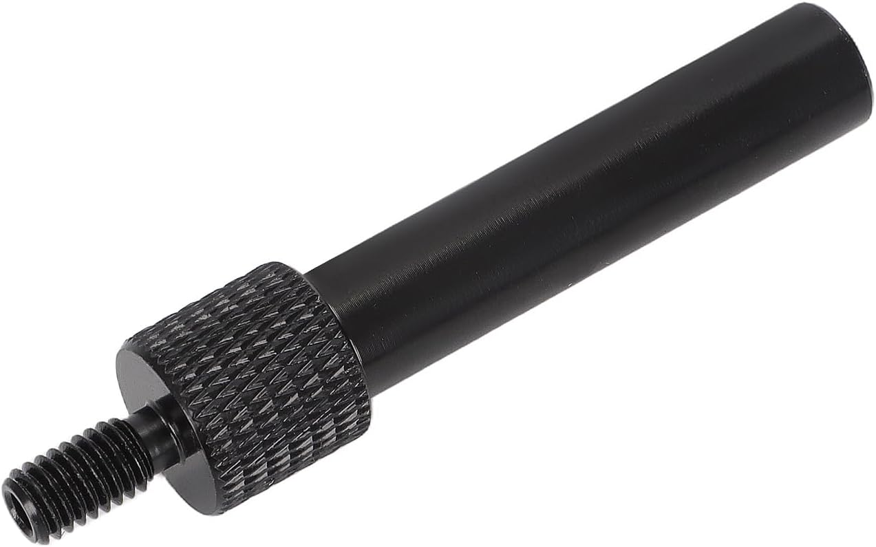
The honest pitch: if you have scoped the signal, confirmed 9 volts and ruled out the carrier, this is the part. If the scope showed corrupted pulses in one direction only, stop and inspect the output carrier windows first, because a new sensor will not fix a pitted reluctor.
Shop the part for this fix →Need something else while the valve body is off? The full 10L80 parts collection carries filters, pan gaskets, planetary sets, solenoid kits and the Sonnax valve body repairs.
Need parts for this job?
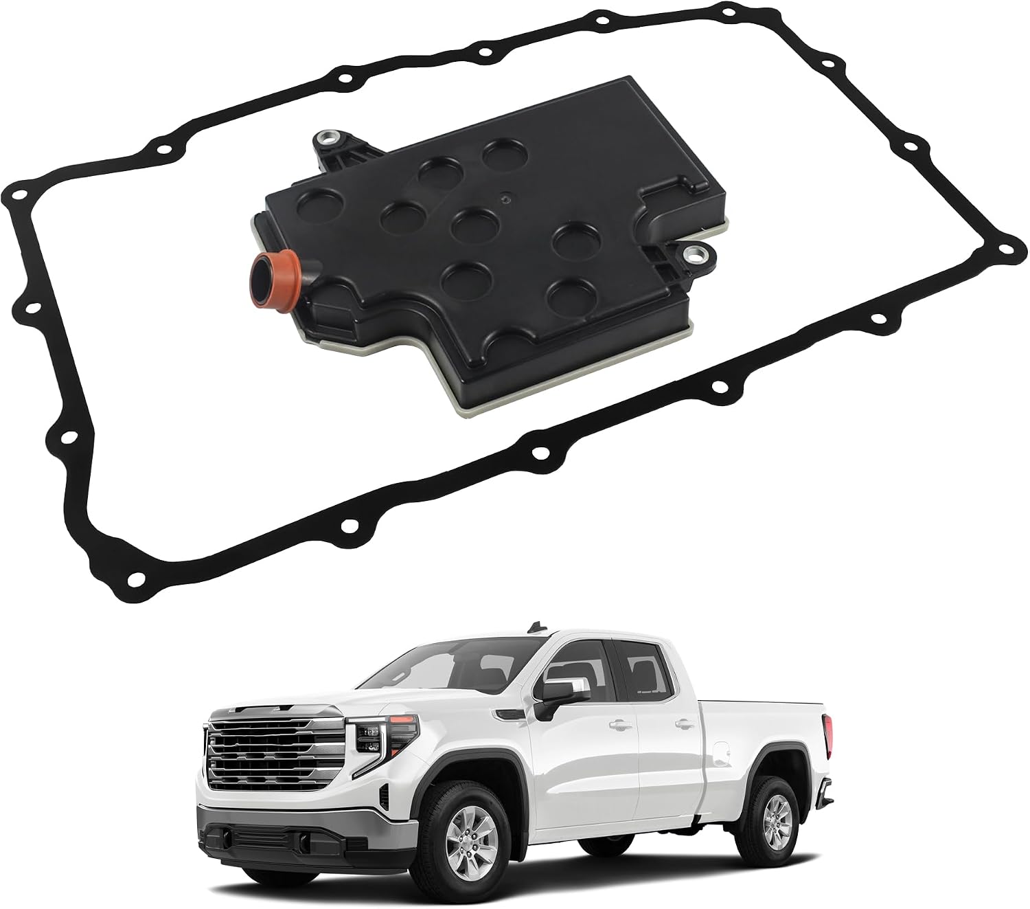
Bench harnesses, filters, pan gaskets, DEXRON ULV and fill adapters are on our 10L80 parts page, with checkout on site. If the pan is coming down for a sensor, put the filter, gasket and fluid on the same order so it only comes down once.
FAQ
What are the symptoms of a bad speed sensor on a 10L80?
It depends which of the four sensors quit. A failed turbine/input sensor usually puts the unit into a commanded neutral state as soon as you select a gear, with the MIL on and P0716 stored. A failed output sensor feels like the truck drops into neutral from a stop, then jerks and goes to limp, and sets P0721. A failed intermediate sensor often shows up only as gear ratio codes, because the TCM uses ISSA and ISSB to confirm clutch states rather than to control the shift directly.
Why do ISSA and ISSB read zero rpm while I am driving?
Because they are supposed to. Transmission Digest documents that ISSA reads the outer lugs on the number 1 ring gear, which the A clutch holds stationary until it releases in seventh gear, so ISSA shows 0 rpm from first through sixth. ISSB reads the sheet metal window on the clutch cylinder, lugged to the front P1 carrier, which the low one-way clutch holds in first and second, so ISSB shows 0 rpm in those two gears and wakes up on the shift to third. Zero on those PIDs in the lower gears is normal data, not a dead sensor.
What is the fastest way to check all four 10L80 speed sensors?
Hold seventh gear in manual mode. Seventh is direct drive, so the entire gear train turns one to one and all four speed sensors should read the same rpm as each other. If one PID is low, erratic or flat in seventh, you have isolated it in one road test instead of chasing gear ratio codes through ten ratios.
Can a bad output speed sensor cause limp mode on a 10L80?
Yes. The TCM compares turbine speed to output speed to calculate the ratio it is actually getting. When the output signal drops out, that math goes invalid, the TCM cannot verify the gear, and it protects the clutches by defaulting. In the Transmission Digest case study of a 10R80 with P0721, the truck jerked from a stop and entered limp mode every time the output signal dropped out on scan data.
Does replacing the speed sensor always fix the code?
No, and that is the expensive lesson in this repair. The sensor only reports what the reluctor gives it. Sonnax documents deteriorating P2 planet magnets that let a vehicle drive 40 to 100 feet before going to neutral, and Transmission Digest documented a 10R80 where pitting in two of the sixty windows of the output carrier corrupted the signal with a new sensor installed. Scope the signal before you order parts.
Related guides
- 10L80 P0716 Causes and Fix
- 10L80 Limp Mode Causes
- 10L80 Valve Body Symptoms
- 10L80 Shift Solenoid Symptoms
- 10L80 Filter and Pan Service
- 10L90 Input/Output Speed Sensor Symptoms
Sources
- Transmission Digest — "Ford & GM 10R80/10L90 Speed Sensor Functions," Mike Souza, January 1, 2019. Backs the four internally mounted two-wire Hall-effect sensors and the 9-volt TCM supply with DC square wave output; the TCM's use of those rpm values for line pressure, shift timing, gear ratio and TCC slip; the input sensor being the only one without a magnetic pickup in the tip, reading 40 magnets bonded in rubber and riveted to the input planet carrier through the non-ferrous transfer shell; the approximately 346.7 kilohm input sensor resistance versus about 4.88 milliohms for the other three; the ISS1/ISSA 50-tooth reluctor welded to the reaction carrier ring gear and 1-2-3-4-5-6 reverse brake clutch hub; the ISS2/ISSB 50-tooth reluctor pressed onto the transfer shell; the OSS 68-tooth reluctor riveted to the output planet carrier; the keyed connector alignment tabs; and the note that connector pin identification differs between the Ford and GM versions. transmissiondigest.com
- Transmission Digest — "10R80 ISSA/ISSB Speed Sensors," Wayne Colonna, May 5, 2026. Backs the per-gear PID behavior used throughout this article: ISSA reading the outer lugs on the No. 1 ring gear held by the A clutch and therefore showing 0 rpm from first through sixth, ISSB reading the sheet metal window on the clutch cylinder lugged to the front P1 carrier held by the low one-way clutch and therefore showing 0 rpm in first and second, TSS and OSS always providing rpm while moving, seventh gear being direct drive with all sensors reading the same rpm, the warning that scan PIDs lag through shifts and should be read in manual shift mode, and the ratio table from 4.696 in first to 0.636 in tenth with 4.866 reverse. transmissiondigest.com
- Transmission Digest — "10R80 gear ratio errors after rebuild," Wayne Colonna, May 16, 2022. Backs the speed sensor performance code assignments P0716 (TSS), P0792 (ISSA), P2746 (ISSB) and P0721 (OSS); the gear ratio DTC list P0731 through P0736, P0729, P076F, P07D9, P07F6 and P07F7; the factory strategy descriptions of each sensor, including the controller comparing turbine speed to output speed to determine gear ratio and ISSA/ISSB monitoring speed and rotational direction of ring gear 1 and carrier 1 / ring gear 4 for clutch state detection; and the documented rebuild in which the output sensor was installed in the ISSB location, cross-connecting the two. transmissiondigest.com
- Sonnax — "Diagnosing Ford 10R60, 10R80 & 10R140 Series Speed Sensor Issues," Jim Mobley. Backs the four two-wire Hall-effect sensors supplied 9 volts; the TSS-swapped-with-ISSA signature of rpm on ISSA in Park and Neutral with zero on TSS and P0716 setting as soon as a gear is selected; the OSS-swapped-with-ISSB signature of normal driving followed by multiple gear ratio codes; the deteriorated P2 planet magnet condition producing a 40 to 100 foot drive before the unit goes to neutral with an incorrect first gear ratio; the ABS test strip check for those magnets; and the scan PID list including TSS-Raw, ISSA-Raw, ISSB-Raw, OSS-Raw, Gear Commanded and Gear Ratio Measured. sonnax.com
- Transmission Digest — "More Than Just a Sensor Glitch: 10R80 P0721 Diagnosis," Sean Mahoney (Certified Transmission), October 15, 2025. Backs the P0721 complaint pattern of feeling like neutral from a stop, jerking and entering limp mode with the output speed signal intermittently dropping out on scan data; the verification of 9 volts at the sensors; the fact that these sensors detect rotational direction so the waveform differs between drive and reverse rotation; the wide-spike drive waveform with a clean reverse signal; the bench test harness built from a 9-volt battery and 220-ohm resistors; the valve body removal sequence including the auxiliary fluid tube and seal, unlocking the internal harness and leaving the center bolt for alignment; the auxiliary stop/start pump sitting over the output speed sensor; and the root cause of pitting in two of the sixty windows of the output carrier, on one side only. transmissiondigest.com
- General Motors — GM TechLink, "2025 Transmission Capacities & Fluids" chart (05-2025 Rev. A). Backs the 10L80 fluid change capacity of 7.7 liters / 8.1 quarts of DEXRON ULV across every listed application (Silverado 1500, Sierra 1500, Tahoe/Suburban, Yukon, Escalade, CT4, CT5), and the separate DEXRON VI and DEXRON HP specifications GM lists for the 6L and 8L units on the same chart. gm-techlink.com (PDF)
- NHTSA — Part 573 Safety Recall Report 26V085, General Motors LLC (GM recall N252536750). Backs the 43,732 2022 Tahoe, Suburban, Yukon, Yukon XL, Escalade and Escalade ESV gas models with the 10-speed and ETRS, the April to September 2022 build window with internal hardware that may increase valve wear, the 5th-gear software remedy, and 2023 and later models built with the software. View source (PDF)
- Transmission Digest — "8L90 Intermittent Failsafe Diagnosis and Cause," August 7, 2026. Backs the GM 8L90 intermittent failsafe traced to a single supply wire rubbed through on a bolt tip along the TCM-to-transmission harness, found with a wiggle test. View source