A 10L90 that "went into neutral" is one of the more expensive phone calls in this business, because three very different failures produce it. A dead turbine speed signal will do it. So will a worn valve body on a car covered by GM's 10-speed recall. So will a planetary carrier that is chewing up the reluctor a sensor reads. Only one of those is fixed with a sensor, and the scan data tells you which one if you know what it is supposed to look like.
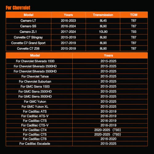
This guide is written for the 10L90 in the cars it actually ships in: Camaro SS and ZL1, the Cadillac V cars and the Escalade. Most published speed sensor tech is written against the Ford 10R80, which shares this gear train. I use that material where it applies and flag the places where the GM side is different. Facts come from GM, NHTSA, Transmission Digest, ATRA's GEARS magazine and Sonnax, all listed at the bottom.


What GM says about the 10L90 speed sensors, and what the teardown shows
Start with GM's own description. The Chevrolet Performance instructions for the Supermatic 10L90 crate unit (P/N 19420481) state that the TCM is externally mounted on this transmission, and that the controller "makes use of three speed sensors." Keep the first fact in mind, because it matters for wiring diagnosis below. Do not lean on the second one.
Mike Souza's teardown of production units at the Seal Aftermarket Tech Center, published in Transmission Digest, found four internally mounted two-wire Hall-effect speed sensors in the shared GM and Ford 10-speed, and he checked both a GM and a Ford unit. Every reluctor tooth count matched between the two. His GM-side names for them:
| GM name | Also called | What it reads | Typical DTC family |
|---|---|---|---|
| Input speed sensor (ISS) | Turbine speed sensor (TSS) | 40 magnets bonded in rubber on a ring riveted to the input planet carrier, read through the non-ferrous transfer shell | P0716 / P0717 |
| Intermediate speed sensor 1 (ISS1) | Intermediate speed sensor A | 50-tooth steel ring welded to the reaction carrier ring gear and 1-2-3-4-5-6-R clutch hub | P0791 - P0794 |
| Intermediate speed sensor 2 (ISS2) | Intermediate speed sensor B | 50-tooth steel ring pressed onto the transfer shell, which carries the output ring gear | P2745 - P2749 |
| Output speed sensor (OSS) | None | 68-tooth steel reluctor riveted to the output planet carrier | P0721 / P0722 |
The TCM sends 9 volts to all four sensors, and each returns a DC square wave whose frequency climbs with reluctor speed. The TCM uses those four speeds for line pressure, shift timing, gear ratio checks and converter clutch slip. Souza also notes that controlled lock-up slip begins shortly after takeoff while still in first gear, so a bad input or output signal hurts converter control as well as shifting.
Two bench facts from the same article are worth writing on the ticket. The input sensor is the only one with no magnet in its tip, because the magnets live in the reluctor. It measured roughly 346.7 kilohms, against about 4.88 milliohms on the other three. That sorts a pile of loose sensors in seconds. And the connectors are color coded with alignment tabs keyed per color, so you cannot cross-plug them. You can put a sensor in the wrong bore, which is how clean rebuilds come back with ratio codes.
One GM-specific caution from Souza: connector pin identification differs between the Ford and GM versions. Borrow Ford's theory and ratios all you want. Take pinouts only from GM information for the RPO in front of you.
Symptoms, sorted by which signal is bad
Input (turbine) speed: the "revs and won't go" car
Sonnax's speed sensor guide for the shared 10-speed is blunt: with an input speed fault, P0716 sets almost as soon as a gear is selected, the MIL comes on, and the unit usually sits in a commanded neutral. Without a turbine speed the TCM cannot compare input to output, so it will not commit a clutch. On a Camaro that is a car that idles fine in Park and flares in Drive.
Output speed: neutral from a stop, then a jerk
Output faults tend to be intermittent for a long time before they are hard. The pattern in Transmission Digest's 2025 case study on the Ford version is textbook: from a stop it occasionally feels like neutral, then it jerks and drops into limp, and on scan data the output signal drops out during exactly those events. Speedometer and cruise behavior can get odd alongside it.
Intermediate 1 and 2: ratio codes and shift quality
These rarely produce a no-move. When one fails you usually see gear ratio codes and a rough or flared shift in the gears that sensor is watching, which is why you need to know when each one is supposed to be active.
Two PIDs read zero on purpose
This is where most good sensors get replaced. Wayne Colonna's 2026 Transmission Digest column lays out the per-gear behavior on the shared gear train:
- Intermediate A (ISS1) reads 0 rpm in 1st through 6th. It reads the No. 1 ring gear, which the A clutch holds until it releases on the 6-7 shift.
- Intermediate B (ISS2) reads 0 rpm in 1st and 2nd. It reads the clutch cylinder lugged to the front P1 carrier, which the low one-way clutch holds in the first two gears. It comes alive on the shift into 3rd.
- Turbine and output always show rpm when moving. Turbine also reads in Park and Neutral with the engine running.
Colonna also warns that the PIDs lag behind real time through a shift. So do not read them on the fly. Hold 7th in manual mode. Seventh is direct drive, the whole gear train turns 1:1, and all four sensors should read the same rpm. One PID low, ragged or flat in 7th picks itself out in a single road test. On a Camaro that means tap-shift mode, which GM's Supermatic instructions say is only available above 7 mph and drops out after 10 seconds without input, so keep tapping.
Check the ratio against GM's numbers
Turbine rpm divided by output rpm is the ratio the unit is actually delivering. Here is where the 10L90 differs slightly on paper. GM's published 10L90 ratios for 3rd through 6th are a hair different from the 10R80 figures most articles print:
| Gear | GM 10L90 (Chevrolet Performance) | 10R80 figure often quoted |
|---|---|---|
| 1st | 4.696 | 4.696 |
| 2nd | 2.985 | 2.985 |
| 3rd | 2.156 | 2.146 |
| 4th | 1.779 | 1.769 |
| 5th | 1.526 | 1.520 |
| 6th | 1.278 | 1.275 |
| 7th | 1.000 | 1.000 |
| 8th / 9th / 10th | 0.854 / 0.689 / 0.636 | 0.854 / 0.689 / 0.636 |
The gap is under one percent and will not change a diagnosis, but quote the GM column on a 10L90 ticket. If the measured ratio matches in every gear and a sensor PID still looks wrong, the sensor is reporting and the fault is elsewhere. If the ratio is wrong in a pattern, ask which sensor feeds that comparison and whether it is in the right bore. Sonnax documents both swap signatures: turbine and intermediate A swapped shows rpm on ISS1 in Park with zero on turbine and sets P0716 on gear selection; output and intermediate B swapped drives and shifts at first, then stacks up ratio codes.
Is it the sensor, the reluctor, or the recall?
On a 10L90 car you have to rule out the recall before you touch a sensor. GM's Part 573 filing for recall 25V-148 (GM N242480630) covers 2020-2022 Camaro, 2020-2021 CT4 and CT5, and 2019-2020 CT6 with the 10-speed. GM's cause is valve body wear that drops pressure and lets valves move unexpectedly, with 115 field reports of lock-up events each under 150 milliseconds. The remedy software detects that wear and limits the transmission to 5th gear with a reduced propulsion message. A car that "lost gears" after a recall visit is showing you a valve body, not a speed sensor. Check recall status first.
If the recall is clear and a signal is dropping out, the next question is whether the sensor or the part it reads is at fault. The sensor only reports what the reluctor hands it, and these reluctors are riveted, welded and pressed to rotating hardware. Two documented failures:
- Turbine magnets. Sonnax reports deteriorated magnets in the P2 planet causing the vehicle to drive 40 to 100 feet and then go to neutral, with a wrong first gear ratio just before the protection kicks in. They check the magnets with an ABS test strip.
- Output carrier windows. In Transmission Digest's P0721 case, a new output sensor and a valve body R and R changed nothing. On the scope, the drive-direction signal showed wide spikes where narrow pulses belonged while reverse stayed clean. These sensors read direction as well as speed. The cause was pitting in two of the 60 windows of the output carrier, on one side only. The fix was a carrier.
Scope it, and prove the wiring
These are two-wire active sensors, so the signal is a current change on the supply circuit, not a voltage pulled to ground on a third wire. ATRA's GEARS series on advanced speed sensors shows the practical way to see one: put a 10-ohm resistor in series and scope the voltage drop across it while the part turns. The same article shows direction encoded in pulse width, about 80 microseconds one way and 160 the other on the sensor it tested. That is exactly why the P0721 case above showed a problem in drive only.
The Transmission Digest case used a bench harness built from a 9-volt battery and 220-ohm resistors to power and scope the sensor off the vehicle at TCM supply voltage. In the car, confirm 9 volts at the sensor first. No supply turns a sensor job into a wiring job.
Because GM mounts the 10L90 TCM outside the transmission, there is external harness between the module and the case connector to check. Transmission Digest's August 2026 write-up on a GM 8L90 with intermittent failsafe is a good reminder of how that goes: the code pointed at a supply circuit shorting to ground, and the cause was one wire rubbed through on a bolt tip along the harness route. Wiggle test the whole run from the TCM to the case connector before the pan comes down.
The other GM rule that bites here: per GM's Supermatic instructions, each controller is flashed with the solenoid characteristics of the transmission it came with. Do not swap TCMs between transmissions to "test" a speed sensor complaint. You will create a shift quality problem on top of the one you have.
Getting to the sensors
The sensors are internal. On the shared 10-speed layout, the pan comes down, the internal harness is unlocked, and the valve body comes off to expose the sensors in the case. Transmission Digest's P0721 case describes the sequence: leave the center valve body bolt in until last as an alignment aid. Put each sensor back in its own bore, check the color and tab of each connector, and verify the harness is fully locked before the valve body goes back on.
Refill with DEXRON ULV only. The Chevrolet Performance instructions list 7.7 L (8.1 qt) for a pan and filter service, say not to use DEXRON VI or HP, and say to check level only after the fluid reaches 70C (158F).
10L80 Output Speed Sensor (fits the shared GM 10-speed family)
The honest pitch: if the scope shows a clean 9-volt supply, a steady carrier and a signal that still drops out, the output sensor is the part. Souza found the reluctor tooth counts identical across the GM and Ford 10-speeds, and the 10L80 and 10L90 use the same sensor design, but confirm the part number against your VIN before you order.
Shop the part for this fix →Need the rest of the job? The full 10L90 parts collection carries filters, clutch plates and valve body repair kits.
Need parts for this job?
The filter and pan gasket kit, DEXRON ULV and a TCM bench harness for testing the module side off the car are on our GM 10-speed parts page (the 10L80 and 10L90 share these service parts), with checkout on site.
FAQ
What are the symptoms of a bad input speed sensor on a 10L90?
Per Sonnax, an input (turbine) speed fault on the GM and Ford 10-speed sets P0716 almost as soon as a gear is selected, turns on the MIL and usually leaves the unit in a commanded neutral. The engine revs in gear and the car does not move, because the TCM cannot compare turbine speed to output speed. Deteriorated magnets in the P2 planet can cause the same complaint after 40 to 100 feet of driving.
Why does my 10L90 scan tool show 0 rpm on an intermediate speed sensor?
That can be normal. Intermediate speed sensor A reads 0 rpm in 1st through 6th because the A clutch holds the ring gear it watches, and intermediate speed sensor B reads 0 rpm in 1st and 2nd because the low one-way clutch holds its carrier. Hold 7th gear in manual mode, where the gear train turns 1:1, and all four speed sensors should read the same rpm.
Can I replace a 10L90 speed sensor without removing the valve body?
No. All four speed sensors are mounted inside the case, so the pan has to come down, the internal harness is unlocked and the valve body comes off to reach them. Budget a filter and pan gasket kit and DEXRON ULV for the refill, which GM lists at 7.7 L (8.1 qt) for a pan and filter service.
Are the 10L90 and 10R80 speed sensors the same?
Transmission Digest found the reluctor rings and planetary tooth counts identical on the GM and Ford 10-speeds it examined, so the sensor theory and gear ratios carry over. Connector pin identification is different between the Ford and GM versions, so use GM wiring information for the pinout and confirm sensor part numbers by VIN.
Related guides
- 10L90 Limp Mode Causes
- 10L90 Valve Body Symptoms
- 10L90 Shift Solenoid Symptoms
- 10L90 Pressure Control (EPC) Solenoid Symptoms
- 10L90 Identification Guide
- 10L80 Input/Output Speed Sensor Symptoms
Sources
- Transmission Digest, Mike Souza, "Ford & GM 10R80/10L90 Speed Sensor Functions" — four internally mounted two-wire Hall-effect sensors, 9-volt TCM supply, GM sensor names (input, intermediate 1 and 2, output), 40-magnet / 50-tooth / 50-tooth / 68-tooth reluctors, 346.7k input sensor resistance, color-keyed connectors, identical tooth counts on GM and Ford units, and different Ford vs GM connector pin identification. Read the article
- Transmission Digest, Wayne Colonna, "10R80 ISSA and ISSB Speed Sensors" (May 5, 2026) — intermediate A reading 0 rpm in 1st-6th and intermediate B reading 0 rpm in 1st-2nd, turbine and output always reading when moving, lagging PIDs, holding 7th (direct drive) to compare all four sensors, and the 10R80 ratio list. Read the article
- Sonnax, "Diagnosing Ford 10R60, 10R80, 10R140 Series Speed Sensor Issues" — P0716 setting on gear selection with a commanded neutral, turbine/intermediate A and output/intermediate B swap signatures, and deteriorated P2 planet magnets causing a 40 to 100 foot drive-then-neutral condition. Read the Sonnax tech article
- Chevrolet Performance, Supermatic 10L90 Transmission Kit instructions (P/N 19420481) — externally mounted TCM, controllers flashed with the solenoid characteristics of their own transmission, GM 10L90 gear ratios, tap-shift availability above 7 mph with a 10-second timeout, DEXRON ULV only, 7.7 L pan and filter capacity and the 70C (158F) level check. Read the GM instructions (PDF)
- NHTSA, General Motors Part 573 Safety Recall Report 25V-148 (GM N242480630) — covered 2019-2022 Camaro, CT4, CT5 and CT6 10-speed vehicles, valve body wear as the cause, 115 lock-up reports under 150 milliseconds, and the remedy software that limits the transmission to 5th gear. Read the recall report (NHTSA)
- Transmission Digest, "More Than Just a Sensor Glitch: 10R80 P0721 Diagnosis" (Oct. 15, 2025) — intermittent output speed dropout with neutral-from-a-stop and limp mode, 9-volt supply verification, direction-sensing waveforms, valve body removal sequence, 9V battery and 220-ohm resistor bench harness, and pitting in two of 60 output carrier windows as the root cause. Read the article
- ATRA / Gears Magazine, "Advanced Speed Sensors Part 2" — scoping a two-wire active sensor through a 10-ohm series resistor, and direction encoded in pulse width (about 80 vs 160 microseconds on the sensor tested). Read the Gears article