P0720 reads "Output Speed Sensor Circuit Malfunction," and on a 4R70W it is one of the few transmission codes where the sensor itself is often the least likely part of the problem. Output shaft speed is the number the PCM builds almost everything else on: shift scheduling, converter clutch apply, electronic pressure control and the speedometer all key off it. Lose it and the unit goes to failsafe in a hurry.
The reason this code eats so much bench time on this family is that Ford changed how the output speed sensor reads speed partway through the transmission's life, and the two designs look close enough to swap without noticing. Get that wrong during a rebuild or a used-unit swap and you have a perfectly good sensor reporting a perfectly wrong number.
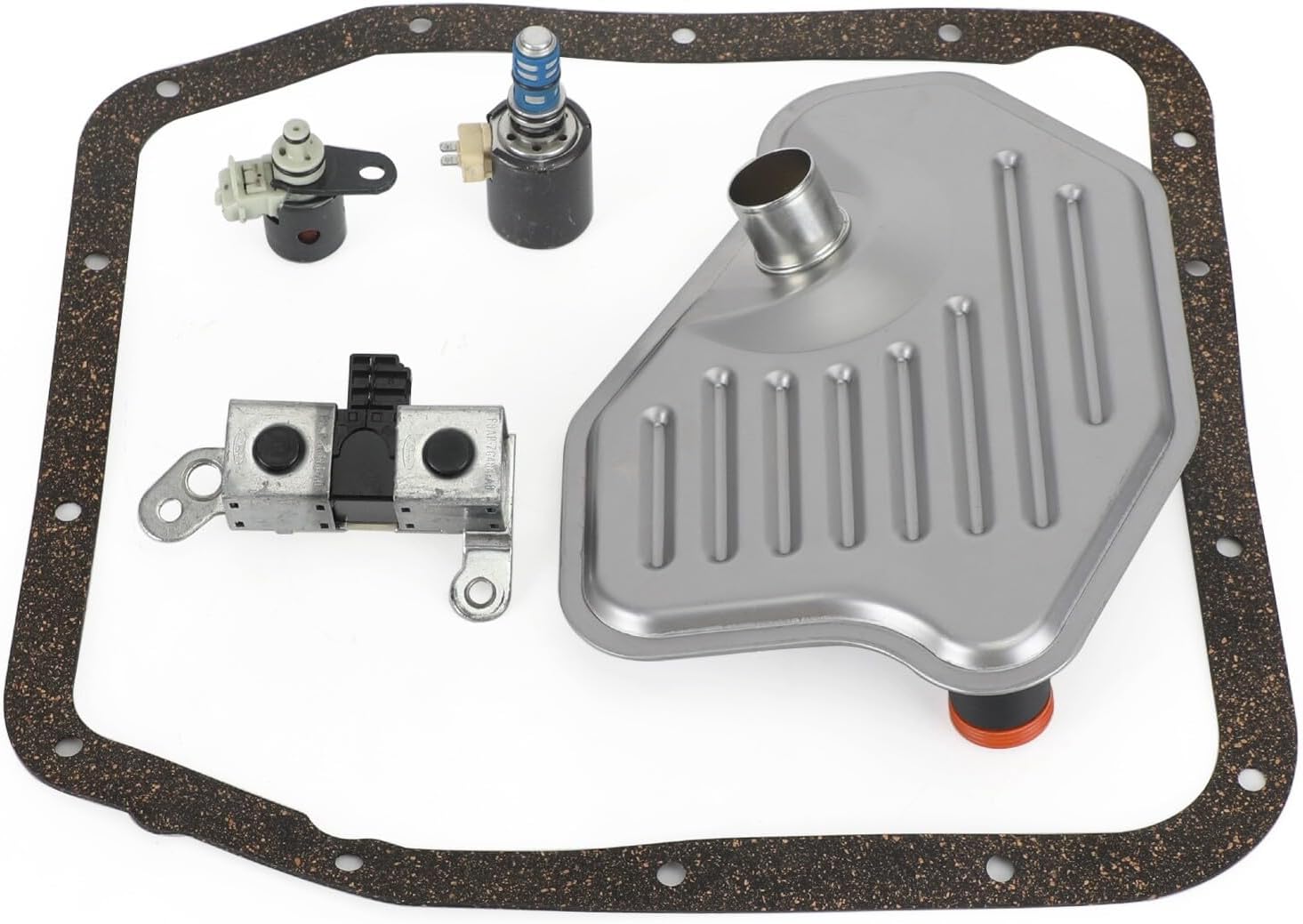

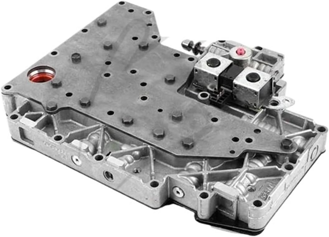
What the OSS Actually Reads on a 4R70W
The output shaft speed sensor on this unit is a two-wire AC pulse generator, not a Hall-effect sensor. There is no power feed to it. It is a coil wound around a magnet, and when a ferrous feature passes the pole tip it disturbs the magnetic field and induces an AC voltage into the winding. Frequency rises with shaft speed; the PCM converts that to a square wave and calls it output speed.
What it counts changed in 2004. Per the ATRA technical manual section on the 4R70W/4R70E/4R75E, the pre-2004 sensor reads six holes machined around the rear ring gear. Beginning with 2004 production, the exciter became 24 extended parking pawl lugs on the ring gear. The sensor was redesigned to match, and the connector had already gone from oval to square back in 2001.
Six features per revolution versus twenty-four. That is the whole story behind most post-rebuild P0720 complaints on this transmission.
Cause 1: A Mismatched Ring Gear or Sensor (The Signature Failure)
ATRA spells out both directions of the mismatch, and the symptoms are specific enough to diagnose from the driver's seat:
- Early ring gear in a late transmission: roughly a 75 percent reduction in output speed sensor signal. The PCM thinks the truck is barely moving and the unit will not shift out of first gear.
- Late ring gear in an early transmission: the signal runs about 400 percent fast. The PCM thinks you are already at highway speed and drops it into fourth by the time you hit 10 mph.
ATRA's verdict on the ring gears is short: no interchange possible. The sensors are nearly as unforgiving. Length is the same from the oval-connector era through 2003, but the 2004-up sensor is shorter to suit the taller lug exciter. Install the shorter late sensor in an 01-03 unit and you get exactly what ATRA describes, a weak signal and intermittent OSS codes, which is the hardest version of this to chase because it passes every static test. Install the early, longer sensor in an 04-up case and it makes contact and gets destroyed.
So before you order anything: confirm what is behind the sensor. Pull the sensor and look. Holes in the ring gear means early. Extended parking pawl lugs means 2004-up. Match the sensor to what you actually see, not to the year on the door jamb of a truck that may be carrying somebody else's used transmission.
Cause 2: The Circuit, Tested Ford's Way
Ford's Powertrain Control/Emissions Diagnosis pinpoint test for the turbine and output shaft speed sensors gives real numbers, and they are worth knowing because the aftermarket repeats a lot of wrong ones.
- Sensor resistance, AODE and 4R70W: between 450 and 750 ohms. Ford's own 1994 AODE workshop manual (Section 07-01, Pinpoint Test F for code 639/P0720) gives the same 450-750 ohm window, then adds a no-continuity check from each sensor lead to ground, a check that the sensor is still magnetized, and a look through the sensor bore to confirm all six ring gear holes are present and free of debris before the sensor is condemned. For contrast, the same test calls for 100-200 ohms on an AX4S and 149-290 ohms on a CD4E, so do not carry a spec across families.
- Where to measure: at the PCM breakout box, test pin 5 for the sensor circuit and test pin 46 for signal return.
- Harness continuity: each leg should read less than 5.0 ohms end to end.
- Live output: on the AC voltage check the reading should vary by more than 0.5 volt as speed changes. A signal that does not swing is a signal the PCM cannot use.
Do the resistance check at the module end, not at the sensor. That single choice tests the sensor and both wires in one measurement, and it is how you catch the failure that actually causes most of these codes, which is not the sensor at all.
Cause 3: Connectors, Harness and the Leadframe Lesson
Ford has documented on its own dime how often OSS complaints are really connection complaints. Two field service programs on the 6R80 make the point plainly. In Customer Satisfaction Program 19N01, Ford wrote that "an output shaft speed (OSS) sensor failure may result in an illuminated malfunction indicator light (MIL) and/or wrench light in the instrument cluster with diagnostic trouble codes (DTCs) P0720, P0722, P0731 and/or P1500 stored in the powertrain control module." The fix was not a sensor. It was the transmission's molded leadframe, the internal wiring carrier, and Ford extended its warranty coverage to 10 years or 150,000 miles to cover it.
Different transmission, same lesson: on an electronically controlled unit the wiring between the sensor and the module fails more often than the sensor does, and the code group it throws is P0720 plus P0722, P0731 and P1500. If you are looking at that exact combination on a 4R70W, work the internal harness and the case connector before you work the sensor.
On the 4R70W specifically, ATRA notes the case connector changed too: 1993-1997 units use a white connector with soft wiring built into it, and 1998-on units use a black connector with a separate hard plastic harness. Solenoids will not interchange because of it, and ATRA's warning is that installing the wrong wiring harness creates multiple codes and erratic shifts. That is worth checking on any unit that has been apart before.
Cause 4: A Sensor That Ohms Fine and Still Fails
Wayne Colonna covered this failure mode in Transmission Digest, and it is the reason a resistance check is a screen and not a verdict. As an AC pulse generator weakens from heat or age, the amplitude of the signal drops while resistance stays in range. The complaints he lists are no upshift into high gear and falling out of gear. Same article: this sensor style is subject to radio-frequency interference, which produces erratic signals and erratic shift and TCC complaints.
Practical version. If the code sets after a long highway pull or on a hot restart and clears when the vehicle cools, suspect the sensor even though it ohms perfect cold. If it sets under hard acceleration on a truck with tired plug wires or an aftermarket ignition box, look at how the speed sensor lead is routed before you condemn anything. A sensor lead zip-tied against secondary ignition wiring is a code waiting to happen.
Colonna also gives the test that separates sensor types when you are not sure what you are holding: a diode test with a DVOM. A two-wire Hall-effect sensor contains a diode and reads two distinct voltages when you reverse the leads. An AC pulse generator has no diode, reads very little, and does not change when you swap leads.
Cause 5: Debris and Damaged Exciter Features
Pull the sensor and look at the pole tip. These are magnets, and they collect the fine ferrous material a worn unit makes. A visible fuzz ball on the tip does not stop the signal cold, it kills amplitude, so it reads fine sitting still and falls apart at road speed. Wipe the tip, then find out where the metal is coming from.
Then inspect the exciter. On a 2004-up unit, chipped or bent parking pawl lugs from a hard park engagement produce a signal with a hole in it once per revolution, which the PCM sees as a speed drop-out. On an early unit, look for damage around the six machined holes in the ring gear.
Diagnosing It on the Scan Tool
Do this before the pan comes down. Sonnax's guidance on Ford speed sensor faults is to make the scanner the primary tool, pull up the transmission PIDs and read them together rather than one at a time. The PIDs you want: engine RPM, turbine or input shaft speed, output shaft speed, commanded gear, measured gear ratio and vehicle speed.
- Static check. In Park at idle, output shaft speed must sit at a clean zero. Noise on the OSS trace with the truck standing still is electrical, not mechanical.
- Rolling check. GEARS Magazine puts the road test simply: monitor OSS data and get the vehicle to move at any speed. If road speed does not register, suspect a bad or swapped sensor.
- Ratio math. Divide turbine speed by output speed and compare against the published 4R70W ratios, roughly 2.84 in first, 1.55 in second, 1.00 in third and 0.70 in overdrive. If the ratio lands on spec, the OSS is telling the truth and you are chasing something else. If it is off by a clean multiple, go back to the ring gear question.
- Watch for the dropout, not the average. Sonnax's method on these units is to compare the raw speed PIDs against each other and let the disagreement tell you which sensor is lying. An OSS trace that goes momentarily to zero while turbine speed and engine speed hold steady is a signal fault, not a slipping clutch.
- Failsafe state. Once the PCM commits to failsafe it stops commanding shifts, so a scan tool showing a fixed commanded gear with the accelerator moving is telling you the code has already taken the unit offline.
Fluid and Level Before Any of This
Check level and condition first, because a low or aerated level causes real slip, and real slip sets ratio codes honestly alongside a sensor code. The 4R70W, 4R70E, 4R75W and 4R75E all specify MERCON V per Ford's own automatic transmission fluid application chart, and that same chart carries an explicit manufacturer caution against supplemental transmission fluid additives, treatments and cleaning agents. Do not pour anything into a unit you are trying to read.
Capacity runs about 5 quarts for a pan and filter service on a typical F-150 or Explorer, and closer to 13 to 14 quarts for a dry fill with a drained converter and cooler lines. Set the final level hot, in gear, on level ground, against the vehicle's own service data.
The Short Version: A P0720 Checklist
- Read all codes. P0720 with P0722, P0731 and P1500 points hard at the output-side circuit.
- Check fluid level and condition cold and hot before anything electrical.
- Pull the OSS. Inspect the pole tip for ferrous debris and wipe it clean.
- Look at the exciter through the hole. Six machined holes means early; 24 extended parking lugs means 2004-up. Confirm the sensor matches.
- Confirm connector style: oval through 2000, square from 2001.
- Ohm the sensor at the PCM breakout box, pins 5 and 46. Spec is 450 to 750 ohms for AODE and 4R70W.
- Check each harness leg for continuity under 5.0 ohms and inspect the case connector and internal harness.
- Verify AC output varies more than 0.5 volt with speed, or scope it for amplitude and dropouts.
- Graph engine RPM, turbine speed and output speed on a road test and do the ratio math yourself.
- Replace the sensor last, match it to the exciter, and route the lead away from ignition wiring.
FAQ
What does P0720 mean on a Ford 4R70W?
P0720 is Output Speed Sensor Circuit Malfunction. The PCM compares the output shaft speed signal against engine speed, turbine speed and the gear it commanded, and the number it is getting back does not hold up. On a 4R70W that can be the sensor, the circuit, or the exciter the sensor is reading, which is either six machined holes in the rear ring gear or 24 extended parking pawl lugs depending on model year.
Why did my 4R70W set P0720 right after a rebuild or a used unit swap?
Almost always a 2004 model year mismatch. ATRA documents that the 2004-up output speed sensor reads 24 extended parking pawl lugs while the earlier design reads six holes machined around the ring gear. Put an early ring gear in a late transmission and the output signal drops about 75 percent and the unit will not shift out of first. Put a late ring gear in an early transmission and the signal runs roughly 400 percent fast, so it grabs fourth by 10 mph.
What should a 4R70W output speed sensor read on an ohmmeter?
Ford's own pinpoint test for AODE and 4R70W applications asks whether resistance is between 450 and 750 ohms measured at the powertrain control module breakout box. Harness continuity on each leg should be less than 5.0 ohms. A sensor that is open, shorted, or well outside that window is condemned, but passing the ohm check does not clear it, because these sensors lose signal amplitude with heat and age while still ohming fine cold.
Will a bad output speed sensor put a 4R70W in limp mode?
Yes. Output shaft speed is what the PCM uses for shift scheduling, converter clutch control and electronic pressure control, so losing it drops the unit into failsafe: one fixed gear, harsh engagement, no converter clutch apply and usually a dead or erratic speedometer. Driving on it puts full line pressure through the clutches on every shift, which is how a sensor complaint turns into a rebuild.
Which codes normally show up with P0720?
Ford's own field service programs on OSS failures list P0720 together with P0722, P0731 and P1500 stored in the PCM with the malfunction indicator lamp and wrench light on. P0722 is no signal at all, P0731 is an incorrect first gear ratio calculated from the same signal, and P1500 is an intermittent vehicle speed sensor fault. Seeing that group points at the output side, not at clutches.
Working a 4R70W this week?
Speed sensors, solenoid kits, valve body parts, filters and rebuild kits — shipped fast from the USA.
Shop 4R70W parts →Sources
- ATRA — "Ford 4R70W/4R70/75E" technical manual section, 2009 (PDF). Backs the core of this article: a new output speed sensor design was incorporated for 2004 using the exciter ring from the 24 extended parking pawl lugs where the old sensor used six holes machined around the ring gear; an early ring gear in a late unit results in a 75 percent reduction in output speed signal and no shift out of first; a late ring gear in an early unit produces a signal 400 percent fast and shifts to fourth by 10 mph; the OSS connector changed from oval to square in 2001; installing the shorter late sensor in 01-03 models can create a weak signal and intermittent OSS codes, while the early sensor in an 04-up will be damaged. Also backs the 1993-1997 white connector versus 1998-on black connector harness change and the warning that the wrong harness creates multiple codes and erratic shifts. atracom.blob.core.windows.net
- Ford Motor Company, Ford Customer Service Division — Customer Satisfaction Program 19N01, April 4, 2019 (PDF via NHTSA). Backs the DTC grouping quoted in this article: "an output shaft speed (OSS) sensor failure may result in an illuminated malfunction indicator light (MIL) and/or wrench light in the instrument cluster with diagnostic trouble codes (DTCs) P0720, P0722, P0731 and/or P1500 stored in the powertrain control module (PCM)," and the fact that the repair was the transmission's molded leadframe rather than the sensor, with coverage extended to 10 years of service or 150,000 miles. static.nhtsa.gov
- Ford Motor Company, Ford Customer Service Division — Customer Satisfaction Program 16N02 Supplement #1, August 17, 2021 (PDF via NHTSA). Backs the intermittent-failure point: an intermittent output shaft speed sensor failure setting the same DTC group with MIL and wrench light, and Ford requiring photos and an IDS log file showing P0720, P0722, P0731 and/or P1500 before a molded leadframe could be ordered. static.nhtsa.gov
- Ford Powertrain Control/Emissions Diagnosis — Turbine Shaft Speed (TSS) / Output Shaft Speed (OSS) sensor pinpoint test (archived service manual copy). Backs every electrical number in this article: AODE and 4R70W sensor resistance between 450 and 750 ohms, breakout box test pin 5 for the sensor circuit and test pin 46 for signal return, harness continuity less than 5.0 ohms per leg, and the requirement that AC voltage vary by more than 0.5 volt while engine speed is varied. Also backs the contrasting AX4S (100-200 ohms) and CD4E (149-290 ohms) specs. diesel-dave.com
- Transmission Digest — "Getting Up to Speed," Wayne Colonna, June 1, 2005. Backs the sensor theory and aging sections: AC pulse generators are wiring wrapped around a magnet whose pulse frequency is proportional to the speed of the rotating part; as the sensor weakens from heat or age the amplitude of the AC signal drops, causing no upshift to high gear or falling out of gear; this sensor style is subject to radio-frequency interference producing erratic signals with erratic shift and TCC complaints; and the DVOM diode test that separates a two-wire Hall-effect sensor from an AC pulse generator. transmissiondigest.com
- Sonnax — "Diagnosing Ford 10R60, 10R80 & 10R140 Series Speed Sensor Issues," Jim Mobley, February 8, 2024. Backs the scan-tool-first method used in the diagnosis section: the scanner is the best mode of diagnosis, pull up the transmission PIDs and read engine speed, turbine speed, output speed, commanded gear, measured gear ratio and vehicle speed together, and use the disagreement between the raw speed PIDs to identify which sensor is reporting incorrectly. sonnax.com
- GEARS Magazine (ATRA) — "Ford's 10R Series Transmission: More Need-to-Know Information Inside the Unit." Backs the road-test step: while monitoring OSS data, get the vehicle to move at any speed, and if road speed does not register, suspect a bad or swapped sensor. gearsmagazine.com
- Ford Customer Service Division — "Automatic Transmission Fluid Chart" (PDF). Backs the fluid section: MERCON V is the specified fluid for the 4R70W, 4R70E, 4R75W and 4R75E, and the chart carries a manufacturer caution against supplemental transmission fluid additives, treatments and cleaning agents. fcsdchemicalsandlubricants.com
- Ford Motor Company — 1994 Mustang Workshop Manual, Section 07-01 (AODE), Diagnostic Trouble Codes and Pinpoint Test F. Backs the factory 450-750 ohm OSS resistance spec, the under-5-ohm harness continuity check, the short-to-ground check, the sensor magnetism check and the six-hole output shaft ring gear inspection for code 639/P0720 on the early (pre-2004) design. fordservicecontent.dealerconnection.com