P0720 is one of those codes that looks like it names its own repair. It does not. On a Ford 5R55W the output shaft speed sensor is the only thing telling the PCM how fast the vehicle is actually moving, and the code Ford stores against it — output shaft speed sensor, insufficient input — covers everything from a corroded pin to a transmission that is not turning the output shaft at all. Two shops out of three replace the sensor, clear the code, and hand the truck back to a customer who is going to see the light again.
This is the order I work a P0720 on a 5R55W, and why each step comes where it does.
What the PCM Is Actually Complaining About
The OSS on this unit is a two-wire variable reluctance pickup mounted externally in the case at the driver-side rear of the transmission, reading a speed rotor on the parking gear that rides on the output shaft. That location matters later, so hold onto it.
The PCM uses that signal for three jobs at once: it calculates vehicle speed from it, it schedules shifts against it, and it decides line pressure and torque converter clutch apply with it. Kill the signal and you do not get one symptom, you get a cluster of them. That is the giveaway. A customer who says "the speedometer died and now it won't shift right" has told you the fault is almost certainly in the output speed circuit, not inside the gearbox.
Ford's monitor is not comparing OSS against nothing. As GEARS put it in its speed sensor primer, the output speed data goes to the module so it can be compared against vehicle speed data, and if the numbers do not agree the computer sets a ratio DTC. The comparison happens fast — that same article notes a ratio fault typically has a fault time of about 0.3 seconds. Three tenths of a second of dropout is enough. This is why intermittents on this circuit set hard codes while the signal still looks fine when you go to check it.
Step 0: Confirm Which 5R55 You Are Holding
Before parts get ordered, know the unit. Sonnax's Bob Warnke laid the family out plainly in "Figuring Out the 5R55 Alphabet": the N ran '99-'02 in the Jaguar S with the 3.0/4.0, the Lincoln LS and the Thunderbird 3.0/3.9, and was replaced by the S in 2003 in the Lincolns and T-Birds. The W showed up in Explorers and Mountaineers for '02-'03 before giving way to the S in the '04-'05 models. The W runs a 24-tooth overdrive sun gear; the S runs a 38-tooth.
Warnke's other warning applies directly here: although the N is similar, only a few parts are interchangeable, and most others create problems if installed in a W/S unit. He points at the solenoid assembly specifically — it appears to interchange across N/W/S, but the base plate and the filter are the critical pieces, and mixing them costs you reverse, TCC apply and solenoid oil pressure. If somebody has been in this transmission before you with a parts-store box, that is worth knowing before you start blaming a sensor.
Step 1: Read the Data Before You Touch a Wrench
Hook up and look at three PIDs together: OSS, TSS and the vehicle speed the cluster is using. Drive it or run it on a lift in gear.
- OSS reads zero, everything else normal. Circuit or sensor, or the reluctor is not turning. If the driveshaft is turning and OSS is flat zero, that is an open circuit until proven otherwise.
- OSS reads, but drops out and recovers. Classic connector or harness fault. This is the one a scan tool will lie to you about.
- OSS tracks smoothly and matches road speed, code still returns. Now you are looking at something else setting the code. Skip to Step 4.
- OSS reads fine, TSS reads fine, but the ratio between them is wrong for the commanded gear. That is a slipping unit, not a sensor problem, and it belongs with the valve body and servo work rather than here.
One method note that saves days: ATRA's technical writing is consistent on this, and it is worth repeating. A scan tool averages the values it displays. Brief dropouts and weak signal amplitude get smoothed right out of the picture. If you suspect an intermittent, put a graphing meter or a scope on the circuit — and put it at the module connector, so you are seeing what the PCM sees rather than what the sensor produced before the harness got hold of it.
Step 2: The 5R55W-Specific Trap Nobody Checks
Here is the thing that makes P0720 more common on this transmission than it has any right to be.
Beginning in 2003, Ford deleted the ATF fill plug from the passenger-side rear of the 5R55W/S case. The boss is still there; the plug is not. Ford's own instructions call for a special tool to pump fluid through the check plug in the pan. Transmission Digest published the workaround the entire industry ended up using instead: remove the output speed sensor on the driver-side rear of the transmission and fill through the output-speed-sensor hole, then set level at the pan check plug as before.
Read that again with a P0720 in front of you. On any 2003-up 5R55W that has ever had a fluid service, the output speed sensor has been out of the case — possibly several times, possibly by somebody in a hurry with a funnel. That gives you a specific list to inspect before anything else:
- Sensor not fully seated. Air gap is everything on a variable reluctance pickup. A sensor standing off the bore by a thread produces a weak signal that dies at low speed first.
- Missing, pinched or hardened O-ring. Leaks fluid down the sensor and into the connector.
- Damaged sensor bore or cross-threaded bolt hole.
- Pigtail routed wrong and rubbed through against the case, crossmember or exhaust after the last service.
- Metal fuzz on the sensor tip. A magnetic pickup collects debris, and a unit that has been apart or is wearing hard supplies plenty of it.
- Connector full of ATF. Fluid wicks into the terminals, corrodes them, and gives you exactly the intermittent that the 0.3 second fault window loves.
Pull the sensor, look at the tip, look at the bore, look at the connector. On a truck with recent service history this is the fault often enough that it should be your first physical check, not your last.
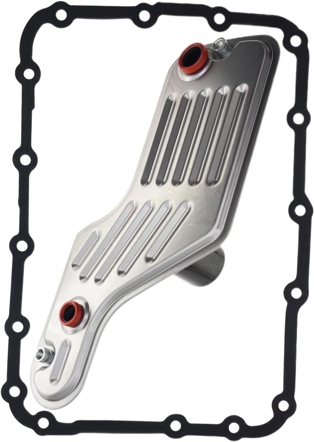
5R55W filter & pan gasket kit → or browse all 5R55W parts
Step 3: Test the Sensor the Way It Actually Fails
Most people put an ohmmeter across a speed sensor, see a number, and call it good. That test proves the winding is not open and not shorted. It proves nothing about signal quality, and the spec spread across applications makes the number close to meaningless on its own — GEARS puts variable reluctance sensor resistance anywhere from as low as 500 ohms on a 41TE to as high as 2,400 ohms on an Allison 2000. If your reading is wildly out of range, you learned something. If it is in range, you learned almost nothing.
The test that matters on a VR pickup is AC output. It is a permanent magnet wrapped in a coil, so it generates its own signal — no reference voltage, no supply wire. Put the meter on AC volts and spin the driveshaft by hand. You want to see real output, and it should climb as you turn faster. For scale, GEARS measured a 2006 Trailblazer VSS producing over 5 volts AC just spinning the driveshaft by hand. A pickup with a wide air gap or a debris-loaded tip will make a fraction of that.
Two VR characteristics are worth carrying into this job:
- VR sensors lose signal strength at low RPM. That is inherent, not a defect. It explains why a marginal sensor sets P0720 pulling away from a stop and looks perfect at 45 mph.
- VR sensors are sensitive to electrical interference from ignition systems, alternators and solenoids. A shield that got left disconnected, or a signal wire re-routed alongside injector or coil wiring during a previous repair, is a real cause of noise-driven codes on this circuit.
While you are back there, put eyes on the reluctor itself. The trigger is the speed rotor on the parking gear — broken lugs, a chewed rotor or a park pawl that has been chattering against it will thin the signal out. And be careful with exchange units on any Ford of this era. Transmission Digest documented the parallel case on the 4R70W/4R70E/4R75E family: for 2004 Ford switched from a ring gear with machined holes to one with extended parking lugs to trigger the OSS, along with a PCM strategy change and a physically different sensor (the 2003-and-earlier all-black sensor is 0.083 inch longer than the 2004-up unit). Mix an early ring gear with a late vehicle and you get no speedometer or a slow one, with DTCs P0720 through P0722 set. Same lesson applies whenever a 5R55 gets swapped: the reluctor and the sensor are a matched pair, and a code that appeared the day a used transmission went in is a pairing problem until proven otherwise.
Step 4: When Something Else Is Setting Your Code
This is the step that separates a diagnosis from a parts swap, and there is a documented case worth knowing.
GEARS covered a vehicle that came in with P0720 forcing the transmission into failsafe. A previous shop had already replaced the output speed sensor twice. The tech backprobed the output speed signal at the transmission control module and scoped it during the failure — and when the transmission went to failsafe, the output speed signal was clean. Nothing wrong with it. Monitoring further found a noisy transfer case potentiometer signal that went bad at exactly the moment the vehicle dropped into failsafe. The transfer case module was setting P0720 on purpose, because it cannot command the transmission into failsafe itself. Replacing the potentiometer fixed it.
The takeaway generalizes: P0720 is a correlation code as much as a circuit code, and on a four-wheel-drive vehicle the speed picture involves more than one module. Before you condemn the OSS on a 4WD or AWD Explorer, pull codes from every module, not just the PCM, and look at the transfer case and ABS data. GEARS makes the same point about wheel speed sensors elsewhere: a faulty wheel speed signal can feed bad data into the network and set gear ratio faults in the transmission without ever setting a fault in the ABS module.
Step 5: What Is Left
If the sensor is good, the circuit is clean at the module, the reluctor is intact and no other module is playing games, then the OSS is telling the truth and the output shaft genuinely is not turning the way the PCM expects. That is a mechanical or hydraulic problem, and on this transmission it usually lives in the valve body.
Warnke's wear order for the 5R55W/S is the map: the TCC modulator bore and main regulator bore wear first because they are the most active, then the VFS 1, 2 and 3 modulator bores wear and reduce clutch and servo pressure. Ford's adaptive strategy hides that for a long stretch, and when the adapts run out of authority the solenoids or the servo pin bore get blamed for what is really modulator valves that can no longer supply enough pressure. A worn bore is not visible — vacuum test or wet air test to find it.
How Common Is This, Really
It is worth calibrating expectations with real fleet data rather than forum impressions. NHTSA's complaint database for the 2003 Explorer — the last model year Sonnax puts the W in that vehicle — holds 1,313 owner complaints, of which 281 were filed under POWER TRAIN and 198 of those specifically mention the transmission or shifting. Of the complaints in that group that state a failure mileage, the median is 110,000 miles, with the middle half falling roughly between 74,000 and 148,000.
That sample is small enough that the median is a rough figure, not a spec. But the shape is useful: these are not infant-mortality failures. They cluster in the second hundred thousand, which is exactly where you would expect accumulated valve body wear, a harness that has seen fifteen summers, and a sensor bore that has been opened for every fluid service since 2003.
Fixing It So It Stays Fixed
- Repair the circuit properly. If a terminal is corroded or a wire is chafed, replace the pigtail or repair with sealed, soldered joints. A crimp butt connector in a spot that sees road spray buys you six months.
- Seat the sensor with a fresh O-ring and torque the retaining bolt properly. Do not guess the depth — the air gap is set by the bore.
- Route the pigtail the way the factory did it. Away from exhaust, secured to its original clips.
- Fill through the sensor hole if you must, but clean it first. If you are going to use the OSS bore as a fill port, do not let sump debris fall past the threads on the way in, and set the final level at the pan check plug.
- Fluid is MERCON V, and the history matters. Sonnax documents that the factory fill in these units prior to May 2005 was an early MERCON V that degraded and took solenoids with it, addressed by Ford with an interim additive under bulletin FSA 04B22 and finally by the revised MERCON V sold as XT-5-QM. If you are servicing an early unit, get all of the old fluid out.
- Clear the code and verify with the OSS PID, not the dash. The speedometer coming back is a good sign, not proof. Watch the PID from a stop through a full upshift sequence and make sure it never drops.
Need parts for this job?
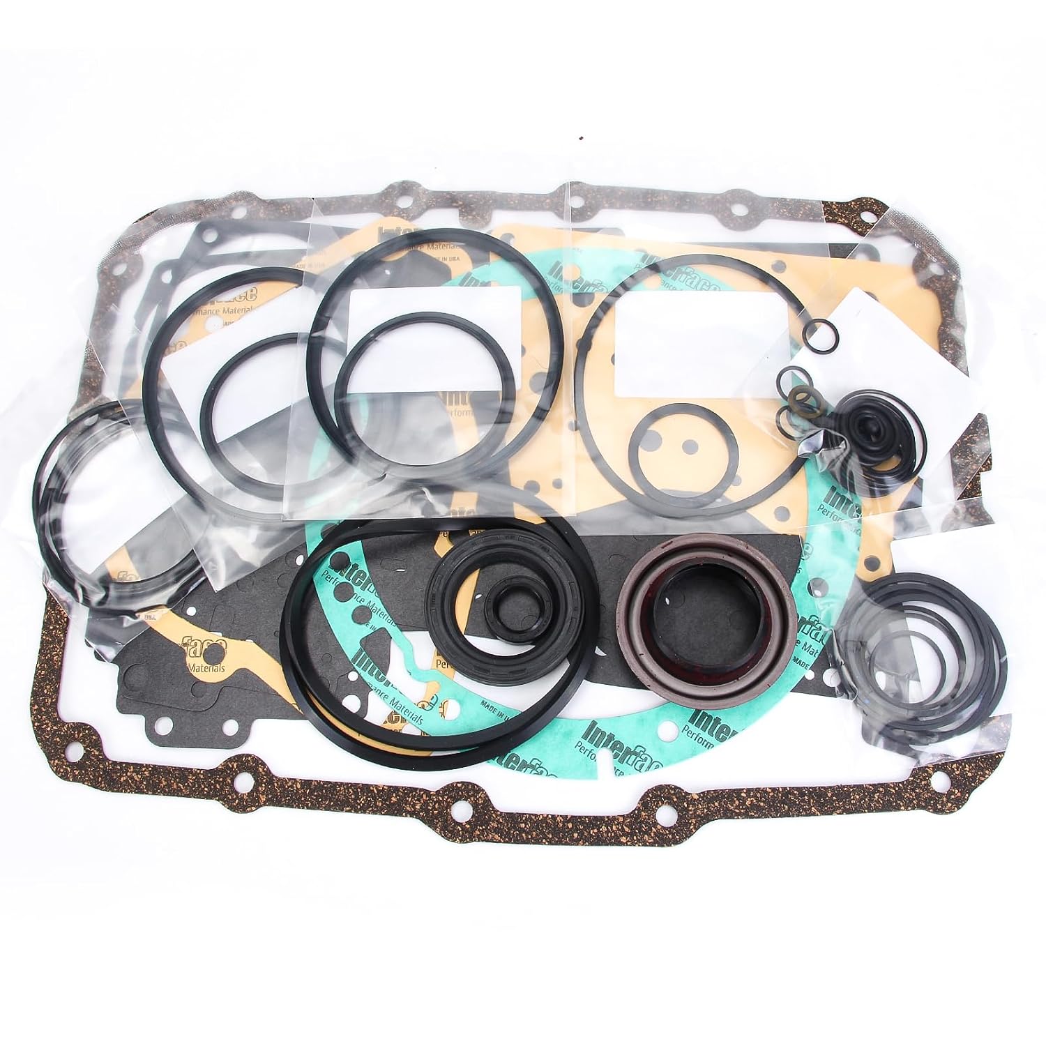
Speed sensors, solenoid packs, filters, valve body kits and full rebuild kits for the 5R55W and 5R55S — the parts side of this diagnosis in one place.
Shop 5R55 parts →FAQ
What does P0720 mean on a Ford 5R55W?
P0720 is the output shaft speed sensor code. Ford's wording for it is insufficient input from the OSS sensor, which means the PCM either lost the signal or is getting one it cannot use. The OSS is the PCM's source for vehicle speed, so when it goes away you normally get a dead or erratic speedometer along with the code, and the transmission drops into a failsafe shift pattern because the PCM has no idea how fast the truck is moving.
Is P0720 always a bad output speed sensor?
No, and replacing the sensor first is how people end up buying two of them. The signal has to survive a connector, a length of harness and the PCM before it becomes a number on a scan tool, and any of that can be the fault. GEARS documented a case where a shop replaced the output speed sensor twice on a P0720 and the actual failure was a transfer case potentiometer, with the transfer case module setting P0720 deliberately to force the transmission into failsafe.
Where is the output speed sensor on a 5R55W?
It is mounted externally in the case at the driver-side rear of the transmission, where it reads a speed rotor on the parking gear riding on the output shaft. On 2003 and later units that same hole is also how you refill the transmission, because Ford deleted the fill plug. Transmission Digest published the field procedure: pull the output speed sensor and pump fluid in through the sensor hole, then set level at the pan check plug.
Can I test the output speed sensor with an ohmmeter?
You can prove it is not open or shorted, and that is all. Variable reluctance speed sensors run anywhere from about 500 ohms on a 41TE to about 2,400 ohms on an Allison 2000 depending on the application, so a resistance number by itself tells you very little about signal quality. The test that means something is AC output: spin the driveshaft by hand with the meter on AC volts and watch for a clean, rising signal. A scope at the PCM connector is better still, because a scan tool averages the value and will hide a brief dropout.
Why does my speedometer quit at the same time the transmission stops shifting?
Because on this transmission they are the same signal. The PCM calculates vehicle speed from the OSS and uses that number for shift scheduling, line pressure and torque converter clutch control. Lose the OSS and you lose the speedometer, the normal shift schedule and lockup all at once. That combination of symptoms is a strong hint the fault is in the output speed circuit rather than inside the transmission.
Sources
- Transmission Digest — "March 2010 Issue," Transmission TECH/TALK. Backs the fill-port trap and the reluctor pairing warning: beginning in 2003 Ford eliminated the fill plug on the passenger-side rear of the 5R55W/S case, and the published workaround is to remove the output-speed sensor on the driver-side rear and fill through the sensor hole, with level set at the pan check plug; and on the 4R70W/4R70E/4R75E family, the 2004 change from a holed ring gear to extended parking lugs (with a matching 0.083 inch shorter OSS sensor and a PCM strategy change) causes no or slow speedometer readings and sets DTCs P0720-P0722 when the ring gear and sensor are mismatched. transmissiondigest.com
- Sonnax — "Figuring Out the 5R55 Alphabet," Bob Warnke, September 19, 2007. Backs the unit identification and the valve body wear order: the N ran '99-'02 in the Jaguar S 3.0/4.0, Lincoln LS and Thunderbird 3.0/3.9 and was replaced by the S in 2003, while the W ran in Explorers and Mountaineers for '02-'03 before giving way to the S in '04-'05; the W uses a 24-tooth overdrive sun gear and the S a 38-tooth; only a few N parts interchange with a W/S and mixing the solenoid base plate or filter loses reverse, TCC apply and solenoid oil pressure; the TCC modulator and main regulator bores wear first, then the VFS 1, 2 and 3 modulator bores, until adaptive strategy runs out and gear ratio codes or slippage occur; and the MERCON V fluid history including bulletin FSA 04B22 and the revised XT-5-QM fluid. sonnax.com
- GEARS Magazine (ATRA) — "Advanced Speed Sensors Part 1." Backs the sensor testing method and specs: variable reluctance sensors are a permanent magnet wrapped with a coil that generates its own signal; resistance varies by application from as low as 500 ohms on a 41TE to as high as 2,400 ohms on an Allison 2000; a 2006 Trailblazer VSS produced over 5 volts AC spinning the driveshaft by hand; and VR sensors lose signal strength at low RPM and are sensitive to electrical interference from ignition systems, alternators and solenoids. gearsmagazine.com
- GEARS Magazine (ATRA) — "Range Rover Transfer Case Problem Puts Transmission into Failsafe." Backs the "another module set your code" case: a P0720 forcing failsafe after a previous shop replaced the output speed sensor twice, where backprobing and scoping the output speed signal at the transmission control module showed the signal was clean during the failure, the transfer case potentiometer signal was noisy at the moment of failsafe, and the transfer case module was setting P0720 to force the transmission into failsafe because it cannot do so directly. gearsmagazine.com
- GEARS Magazine (ATRA) — "Do You Know How Fast You Were Going?" Backs the monitor logic and timing: transmission output speed sensor data is sent to the ECM/TCM so it can compare vehicle speed data with OSS data, a ratio DTC is set when the numbers disagree, a ratio fault typically has a fault time of 0.3 seconds, and a faulty wheel speed sensor signal can set gear ratio faults in the transmission without setting a fault in the ABS module. gearsmagazine.com
- NHTSA — Office of Defects Investigation complaint database, 2003 Ford Explorer (complaintsByVehicle API). Backs the fleet numbers: 1,313 total owner complaints on file, 281 filed under the POWER TRAIN component, 198 of those mentioning the transmission or shifting, and a median stated failure mileage of 110,000 among the complaints in that group that report one. Counts retrieved September 7, 2026. api.nhtsa.gov