P1744 is Ford's own converter clutch code, and the wording matters: torque converter clutch system performance. Not circuit. Not solenoid. System. The PCM commanded the clutch to apply, watched engine speed against turbine speed, and the two never came together the way the calibration says they should. Everything between the solenoid connector and the clutch lining is still a suspect.
On a 5R55W you will usually see P1744 alongside P0741, because they are two names for the same failed slip test — one generic, one Ford-specific. That is not a problem. It just means the code cannot narrow anything for you, and the narrowing has to come from a test sequence instead. What follows is that sequence, in the order that keeps you from paying for parts twice.
Ford's own 5R55W/S diagnosis manual shows how the PCM gets there. It runs the converter clutch through a single pulse-width modulated TCC solenoid, and its code table defines P0741 as a TCC engagement error with no TCC operation or TCC slips. The same table lists P1740, a mechanical failure of the TCC solenoid, where a solenoid stuck on stalls the engine at low idle and one stuck off gives no TCC engagement. Ford also notes that the fault has to repeat on 5 consecutive drive cycles before P0741 or P1740 is stored in continuous memory, so a single clean road test after a repair proves nothing.
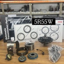
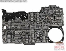
Step 1: Set the Fluid Level Correctly, Before Anything Else
This is not filler advice on a 5R55W. There is no dipstick, the level plug is buried in the middle of the drain plug, and Ford wrote a bulletin about it because shops were misdiagnosing units over it. Ford TSB 01-7-6 opens with exactly that: improper checking of the transmission fluid level may result in the misdiagnosis of transmission concerns.
The procedure in that bulletin is specific, and every number in it changes the answer you get:
- Monitor transmission fluid temperature on the scan tool using PID TFT.
- Idle the engine — the bulletin notes idle speed is approximately 650 RPM — until fluid temperature is between 27 and 49 degrees C (80 to 120 degrees F).
- Cycle the range selector slowly through every gear, pausing to let each one engage, then park it.
- Raise the vehicle with the engine running and level it. Ford calls for special tool 205-025 to get it as close to level as possible, and on a lift that is not a formality — a nose-up truck reads full when it is not.
- Hold the larger drain plug with a wrench and remove the small center level plug with a 3/16 inch Allen key.
- Wait about a minute. When fluid exits as a thin stream or a drip, the level is correct. If nothing comes out, add MERCON V in 0.24 L (1/2 pint) increments until it does.
- Reinstall the center plug and torque it to 10 Nm (89 lb-in). That is inch-pounds. It is an aluminum pan.
Now the part the bulletin does not tell you. On a worn 5R55W the level itself can be lying. Sonnax notes that excessive leakage anywhere in this valve body increases foaming of the oil, and that foaming increases the venting action from the breather. Aerated fluid occupies more space than solid fluid, so a badly worn unit can read overfull, push oil out the vent, and then run low. If you set a level, drive it, and find it different again, treat that as evidence about the valve body rather than as a leak hunt.
Step 2: Know the Fluid History
The 5R55 family has a documented factory fluid problem that still bites units today. Per Sonnax, the fluid problem in the 5R55E, W, S and N units was caused by a factory ATF fill using an early MERCON V, prior to May 2005, which degraded the solenoid assembly. Ford released an interim additive package, part 4L2Z-19B546-AB (fluid XL-11), under bulletin FSA 04B22, to install into customer and new-vehicle inventory. The final resolution was a revised MERCON V.
Two working consequences. First, a partial drain that leaves questionable fluid in the converter and cooler can shorten the life of the next solenoid assembly, so if you are in there, get the old fluid out. Second, if you install a replacement solenoid assembly, prime it. Sonnax is explicit: the assemblies are tested and shipped with fluid, but that lubricant drains off during handling, and a loss of prime in the variable force solenoids reads as a malfunctioning new part. Fill the circuits with new MERCON V and pull fluid through the solenoid with vacuum before it goes in. Units built after 2002 use adaptive strategy, so do a relearn with the solenoid service.
Step 3: Read Slip the Right Way on the Scan Tool
Converter clutch slip is engine RPM minus turbine shaft speed. Graph both, add commanded TCC duty cycle, and road test at a steady cruise where the PCM wants lockup. Three patterns, three different repairs:
- Slip never falls at all when duty cycle is commanded. The command is not reaching the clutch. Suspect the solenoid, its feed, or a control valve that is not stroking. Ford's spec for the TCC solenoid is 9-16 ohms (the shift solenoids are 16-45), so meter it before you condemn the valve body.
- Slip drops partway, then climbs back up as load increases. This is the classic hydraulic shortfall, and it is the single most common P1744 pattern on this unit. Sonnax lists "high TCC slip RPM at increasing load" as a symptom of TCC modulator plunger sleeve wear. If your customer only sets the code towing or on a grade, this is your fault line.
- Slip goes to essentially zero and stays there, but converters keep failing. Read the overpressure section below before you call it healthy.
Do not skip the input side either. Slip is calculated from turbine speed, so a turbine shaft speed sensor giving a lazy or noisy signal can fabricate slip that is not there. If P0715 or P0716 is in memory with the P1744, chase the sensor first.
Step 4: Prove It Hydraulically With the Wet Air Test
Here is the test that separates real 5R55W diagnosis from parts-swapping, and it works with the transmission still in the vehicle. Writing in Transmission Digest, Sonnax vice president of technical development Bob Warnke describes making a test plate out of the aluminum base plate that comes off the 5R55W/S solenoid assembly. Reattach that plate over the separator plate, then inject ATF along with regulated air at 40 to 60 psi — the wet air test, or WAT.
His point about sequence is the one worth internalizing: the common practice is to remove the valve body, disassemble the valves and look at the bores, and when we do that, we remove the evidence from the case. Warped valve bodies, stuck valves, blown gaskets, worn bores and loose bolts get overlooked unless you test the circuits first.
Warnke's map of normal circuit function on the 5R55W/S is worth taping inside the toolbox lid:
- SSA: intermediate select valve strokes; direct clutch control valve strokes.
- SSB: intermediate control valve strokes.
- SSC: overdrive servo control strokes.
- SSD: coast clutch control strokes; reverse servo control strokes.
- VFSA-1: VFS 1 modulator valve and boost valve stroke.
- VFSB-2: reverse engagement control, boost valve, VFS 2 modulator valve and forward engagement control valves stroke.
- VFSC-3: reverse modulator valve strokes.
- TCC: converter pressure modulator and converter control valve stroke.
That last line is your P1744 test. Air into the TCC circuit should stroke the converter pressure modulator and the converter control valve, and they should follow smoothly as you throttle air pressure up and down. Oil loss at any location is a loss of the solenoid oil force that is supposed to be clamping your converter clutch. How much it leaks depends on air pressure, the ATF in the circuit and the severity of bore wear, which is why Warnke recommends practicing on a known-good unit first so you know what normal looks like.
Watch the exhaust slots too. Sonnax notes that leakage visualized around a valve or slot aerates the fluid in operation, which loops right back to the false level reading from Step 1.
Step 5: Vacuum Test the Bores That Actually Fail
Once the valve body is out, vacuum testing tells you which specific bore is finished. Sonnax publishes a Ford 5R55W/S Vacuum Test Guide that maps the critical wear areas and test locations on this exact casting, and the converter clutch group is well documented on it. Plug the casting valley to isolate circuits, test valves in their rest position unless the instructions say otherwise, and compare against the minimum in-Hg listed in the individual part instructions.
For inspection order, Warnke gives a shortcut based on activity: on a 5R55W/S valve body, start with the TCC modulator bore, then the main regulator bore. Those two wear first. As cycle rate climbs, and it climbs hardest in stop-and-go city driving, the VFS 1, 2 and 3 modulator bores follow, reducing clutch and servo pressure. Adaptive strategy hides that for a while, then gear ratio codes or slippage appear.
The two parts that come up most on a P1744 unit:
- TCC modulator valve, Sonnax 56947J-15K. Sonnax states bore wear at the TCC modulator reduces TCC apply pressure and the low apply results in increased TCC slippage. Listed symptoms are code P0741, excess TCC slip, code 1783, high line pressure and an overheated transmission. Worth noting: Sonnax says these complaints often occur at relatively low mileage on this family, so an otherwise clean unit is not exempt. The kit ships two springs — white and shorter for 5R55W and 5R55S, plain and longer for 5R55N.
- TCC modulator plunger valve, Sonnax 56947J-01K. The cause here is wear at the inside diameter of the plunger sleeve, driven by constant oscillation of the pulse width modulated TCC solenoid. The plunger positions the inner modulator valve, which feeds line to the apply circuit and sets slip rate. Sonnax also warns that the valve bore inward of that sleeve wears rapidly, so always inspect the largest spool of the inner valve. Replacing the sleeve and leaving the bore behind it is a comeback.
5R55W TransGo shift kit / valve body rebuild kit → solenoid block pack with filter or all 5R55W parts
The Overpressure Trap: When Low Slip Is Bad News
P1744 is a slip code, so it is tempting to treat tight slip numbers as proof of a good repair. On a 5R55W that assumption has killed converters.
Warnke lays out the circuit. Converter release oil holds the TCC piston off the cover, supplies charge pressure and then flows to the cooler; it comes from the converter regulator valve and is limited to 130 psi. TCC solenoid pressure feeding the modulator sleeve is supposed to be limited to 72 psi by the solenoid regulator valve. A back pressure valve holds 8 to 12 psi on the release oil to help control slip and lube pressure. Once the TCC control valve strokes, release oil is redirected to the cooler and modulated line pressure becomes converter apply pressure — and Warnke puts available line at 160 to 250 psi and up.
Here is the trap. If that 72 psi limit is altered, or the solenoid regulator bore is worn at the inboard end, pressure keeps rising at the modulator valve sleeve. Higher pressure reduces slippage. The scan data looks better. But Warnke's warning is that it can cause TCC piston deflection and converter failure. So on a unit that has already had a shift kit or previous valve body work, suspiciously tight slip deserves a pressure check rather than a pat on the back.
Cooler Flow, the Thermal Element, and Why P1744 Units Run Hot
Overheating is one of the most common complaints filed alongside P1744, and the reason is structural: converter apply redirects release oil to the cooler. A converter clutch circuit that cannot switch cleanly starves the cooler at exactly the moment the converter is generating the most heat.
There is a second heat path specific to this design. Fluid leaving the converter passes over a thermal element that begins to open around 125 degrees F. Before it is fully open, fluid circulates internally for lube with no external cooler flow. When it does open, the converter charge purges, internal pressure drops, and the void fills with cool fluid, which retracts the thermal element and starts the cycle again. Sonnax notes this can produce erratic fluid level and, in some situations, converter overheat — another reason a level reading on a hot, unhappy 5R55W is not a stable number.
For diagnosis: once the unit is at operating temperature, you can watch the converter command and valve stroke as a spike in cooler flow. Sonnax's caution is the useful part — if the TCC modulator bore, TCC control valve bore or the solenoid gasket leaks, that change in flow is very subtle. Do not expect an obvious surge. And if flow is always low out of lockup and drops significantly in reverse, look at the pump: the line control valve may be sticking open, the pump may be misaligned, or the gear pocket may be worn.
Repair Order That Does Not Come Back
- Set the fluid level per TSB 01-7-6 and inspect the fluid. Fix nothing else until this is right.
- Scan for company codes. Speed sensor faults, pressure control codes and overheat code 1783 all change the story. Ford sets P1783 when fluid reaches 270°F (127°C) and raises PC pressure in response.
- Road test with engine RPM, turbine speed and commanded TCC duty cycle graphed. Classify the slip pattern.
- Wet air test the solenoid circuits at 40 to 60 psi with the base plate over the separator plate, in the vehicle, before disassembly.
- Pull the valve body and vacuum test. Start at the TCC modulator bore and the main regulator bore.
- Recondition the bores that fail and fit the correct valve kits. Inspect the bore inward of the modulator sleeve.
- Verify the solenoid base plate and filter are the correct W/S parts. Mixing N and W/S pieces costs reverse, TCC apply and solenoid oil pressure.
- Refill with MERCON V, prime any new solenoid assembly, and run the adaptive relearn.
- Re-road test and confirm slip drops to near zero and stays there under load, not just on flat ground.
Replace the converter when the evidence says the converter: clutch lining debris in the pan, a converter that failed after a documented overpressure condition, or a unit that still slips with a valve body proven to hold pressure. Replacing it first, in front of a worn casting, is the most expensive way to not fix a P1744.
Need parts for this job?
Valve body and TCC valve kits, solenoid block packs, filters, gaskets, bands and full rebuild kits for the 5R55W and 5R55S — all in one place.
Shop 5R55 parts →FAQ
What is the difference between P1744 and P0741 on a 5R55W?
Both are converter clutch slip performance codes and both are set by the same monitor watching the same numbers, so on a 5R55W they very often appear together. P0741 is the generic OBD-II code for torque converter clutch circuit performance or stuck off. P1744 is Ford's manufacturer-specific version, described as torque converter clutch system performance, and it points at the mechanical and hydraulic side of the system rather than at an open or short in the solenoid wiring. Neither code tells you which part failed, so the diagnostic path is the same for both.
Do I have to replace the torque converter to fix P1744 on a 5R55W?
Usually not, and doing it first is how shops buy this repair twice. On the 5R55W the pressure that clamps the converter clutch is produced and modulated in the valve body, and Sonnax documents that wear at the TCC modulator valve bore reduces apply pressure to the converter clutch and increases TCC slippage. If you fit a new converter to a valve body that still leaks apply oil, the new clutch lining wears out on the same schedule as the old one. Prove the hydraulics hold pressure before you condemn the converter.
Why does the fluid level have to be set before diagnosing P1744?
Because the 5R55W has no dipstick and a wrong level changes converter charge directly. Ford TSB 01-7-6 states plainly that improper checking of the transmission fluid level may result in misdiagnosis of transmission concerns, and specifies the procedure: monitor the TFT PID, run the engine at roughly 650 RPM idle until fluid temperature is between 27 and 49 degrees C, then remove the small center level plug with a 3/16 inch Allen key and set the level until fluid exits as a thin stream or drip. There is a second trap on this transmission: worn valve body bores aerate the fluid, and that foam raises apparent level and vents from the breather, so the level you read can be a symptom rather than a cause.
Can I test the 5R55W converter clutch circuit without removing the valve body?
Yes, and on this transmission you should. Sonnax vice president of technical development Bob Warnke describes making a test plate from the 5R55W/S solenoid assembly aluminum base plate, reattaching it over the separator plate, and injecting ATF along with regulated air at about 40 to 60 psi. He notes this can be done with the transmission still in the vehicle, and that pulling the valve body apart first removes the evidence: warped bodies, stuck valves, blown gaskets, worn bores and loose bolts all get overlooked once the parts are on the bench.
Which fluid does a 5R55W take, and does fluid history matter for P1744?
MERCON V, and yes it matters. Sonnax documents that the factory ATF fill in 5R55E, N, W and S units prior to May 2005 used an early MERCON V that degraded the solenoid assembly. Ford released interim additive package 4L2Z-19B546-AB, fluid XL-11, under bulletin FSA 04B22, and the final resolution was a revised MERCON V. If any trace of the questionable fluid is left behind during a service, the service life of the next solenoid assembly can be reduced, so get the old fluid out rather than doing a partial drain and refill.
Sources
- Ford Motor Company — Technical Service Bulletin, Article No. 01-7-6, "Transmission — 5R55W — Correct Transmission Fluid Checking Procedure" (PDF). Backs the entire fluid level section: the statement that improper checking of the transmission fluid level may result in misdiagnosis of transmission concerns; monitoring PID TFT; approximately 650 RPM idle speed; the 27 to 49 degrees C (80 to 120 degrees F) fluid temperature window; cycling the range selector through each gear; special tool 205-025 for leveling the vehicle; removing the small center fluid level indicating plug with a 3/16 inch Allen key while holding the larger drain plug; the one-minute wait and thin-stream-or-drip level indication; adding fluid in 0.24 L (1/2 pint) increments; and the 10 Nm (89 lb-in) plug torque. Ford TSB 01-7-6 (PDF)
- Sonnax — "Figuring Out the 5R55 Alphabet," Bob Warnke, September 19, 2007. Backs the hydraulic figures and several diagnostic points: converter release oil from the converter regulator valve limited to 130 psi; TCC solenoid pressure limited to 72 psi by the solenoid regulator valve, and a worn solenoid regulator bore at the inboard end allowing pressure to rise, reduce slip and cause TCC piston deflection and converter failure; modulated line pressure of 160 to 250 psi and up becoming converter apply pressure once the TCC control valve strokes; the back pressure valve holding 8 to 12 psi on release oil; the TCC modulator bore and main regulator bore wearing first with VFS modulator bores following; the wet air test with the base plate over the separator plate at 40 to 60 psi; aerated fluid from bore leakage creating false level and breather venting; the thermal element beginning to open at 125 degrees F and the resulting erratic level and converter overheat; the subtle cooler flow change when TCC bores or the solenoid gasket leak, and low flow in reverse pointing at the pump line control valve; the solenoid base plate and filter not interchanging between N and W/S without losing reverse, TCC apply and solenoid oil pressure; and the pre-May-2005 MERCON V fluid problem, interim additive 4L2Z-19B546-AB (XL-11) under bulletin FSA 04B22, VFS solenoid priming by vacuum, and the post-2002 adaptive relearn. sonnax.com
- Transmission Digest — "Tools That Money Can't Buy and They Pay You to Use," Bob Warnke, TASC Force Tips, December 1, 2004. Backs the wet air test procedure and the solenoid circuit map: building a test plate from the 5R55W/S solenoid assembly aluminum base plate; the 5R55W/S having problems with slip codes, TCC shudder and delayed engagement; the warning that removing and disassembling the valve body first removes the evidence of warped bodies, stuck valves, blown gaskets, worn bores and loose bolts; testing with ATF and regulated air of about 40 to 60 psi in the vehicle; and the normal-function circuit list for SSA, SSB, SSC, SSD, VFSA-1, VFSB-2, VFSC-3 and the TCC circuit stroking the converter pressure modulator and converter control valve. transmissiondigest.com
- Sonnax — TCC Modulator Valve Kit 56947J-15K, product and cause data. Backs the TCC modulator bore section: bore wear at the TCC modulator reduces TCC apply pressure, and the low apply results in increased TCC slippage; listed symptoms are code P0741, excess TCC slip, code 1783, high line pressure and overheated transmission; converter slip complaints on 5R55N, W and S often occur at relatively low mileage; wear at the TCC modulator valve bore reduces apply pressure to the converter clutch and line pressure; excessive leakage anywhere on this valve body increases oil foaming and breather venting; and the kit includes two springs, white and shorter for 5R55W and 5R55S, plain and longer for 5R55N. sonnax.com
- Sonnax — TCC Modulator Plunger Valve Kit 56947J-01K, product and cause data. Backs the plunger sleeve section: wear at the inside diameter of the TCC modulator plunger valve sleeve caused by constant oscillation of the pulse width modulated TCC solenoid; the plunger positioning the inner modulator valve, which feeds line to the apply circuit and controls slip rate; sleeve wear allowing slip rate to keep rising and potentially preventing full lockup; listed symptoms of slip codes, high TCC slip RPM at increasing load and overheated fluid; and the note that the valve bore inward of the modulator sleeve wears rapidly and must be inspected at the largest spool of the inner valve. sonnax.com
- Sonnax — "Ford 5R55W/S Vacuum Test Guide," February 21, 2013. Backs the vacuum test section: the critical wear areas and vacuum test locations for this specific casting; testing OE valves in the rest position unless otherwise indicated; plugging the casting valley with foam, putty or an O-ring to isolate circuits; referring to individual part instructions for specific vacuum test information; and the TCC modulator and TCC control valve groups being listed against code P0741, excess TCC slip, TCC lining failure, overheated fluid and high TCC slip RPM at increased load. sonnax.com
- Ford service information via Mitchell1, "2002 Automatic Transmissions 5R55W/S Diagnosis" (Explorer/Mountaineer, PDF). Backs the PWM TCC solenoid description (stuck on: rough running and stall at low idle; stuck off: no TCC engagement), the P0741 definition (no TCC operation or TCC slips), P1740 TCC solenoid mechanical failure, the 5-consecutive-drive-cycle requirement before P0741/P1740 set continuous memory, the 9-16 ohm TCC solenoid and 16-45 ohm shift solenoid resistance specs, and P1783 at 270°F with increased PC pressure. Ford/Mitchell diagnosis (PDF)