"It bangs into gear" and "it sits there for a second before it goes" are the two most common 10R80 complaints that walk through a shop door, and they are frequently the same vehicle. The problem is that both symptoms have at least five plausible causes, and four of them are cheaper to fix than the one most shops jump to. I have watched units get pulled and overhauled for a condition that a battery and a drive cycle would have fixed. This walkthrough is the order I work them in, with the checks that actually eliminate causes rather than just moving suspicion around.
For more on Ford applications, see our Ford transmission hub.
Know What You Are Working On First
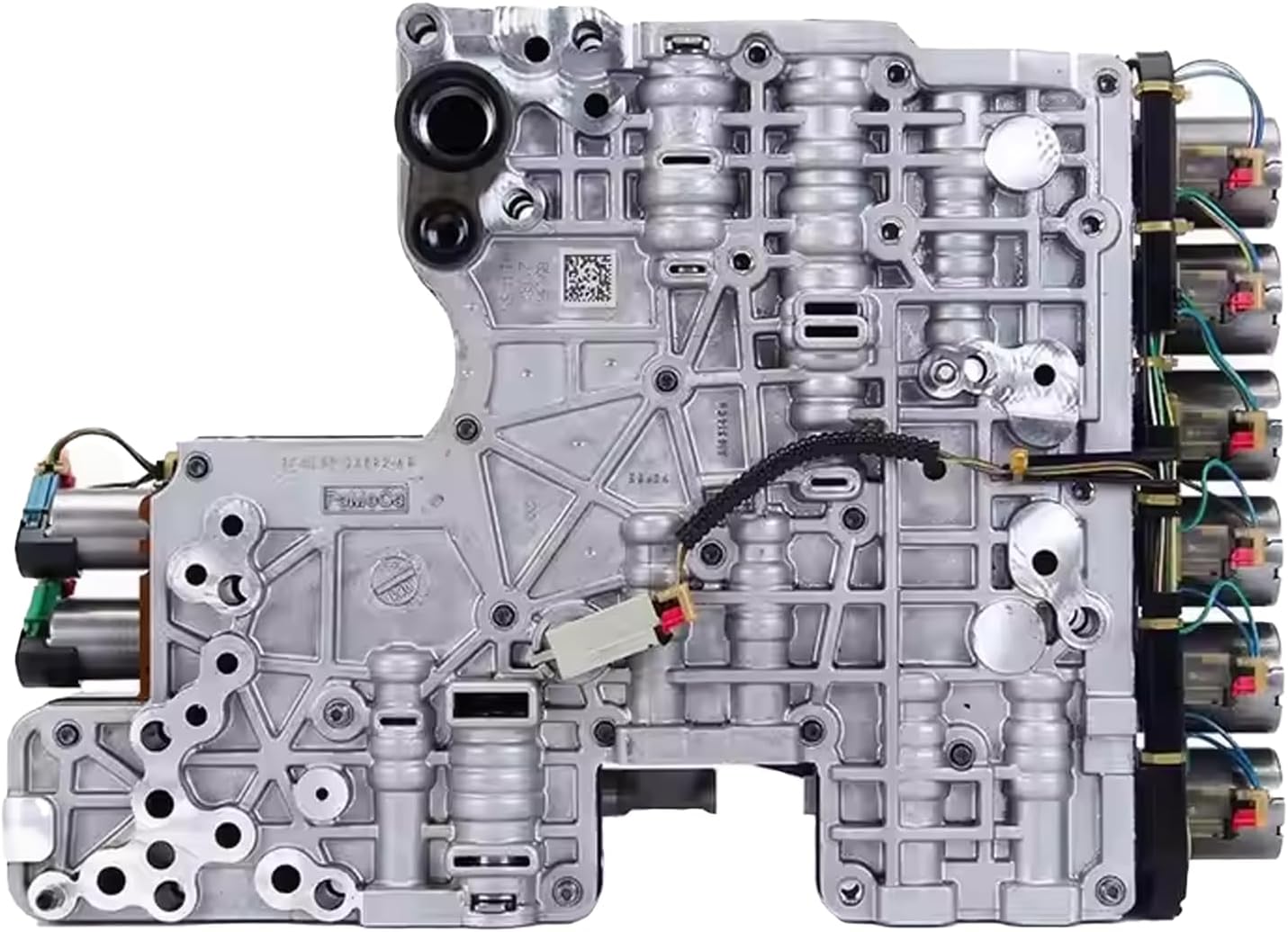
The 10R80 uses six shift solenoids that Ford calls Casting-Integrated Direct-Acting Solenoids, or CIDAS. Per ATRA's Gears magazine breakdown of the 10-speed family, these are mechanical — no transmission fluid passes through the solenoid itself. An armature and pin assembly moves a valve in the main valve body directly. Each clutch (A through F) has a matching shift solenoid (A through F), and the relationship is directly proportional: zero current equals zero pressure, maximum current equals maximum pressure.
That one fact changes how you think about this unit. Because there is no pressure at zero current, no clutch pack can engage if power to the shift solenoids is interrupted. Sonnax makes the same point from the bench side — a 10-speed has no movement at all when unplugged from the electrical source. Compare that to an older unit where a dead solenoid leaves you limping home in a default gear. On a 10R80, electrical problems and hydraulic problems produce overlapping symptoms, which is exactly why harsh and delayed shift diagnosis on this unit goes sideways so often.
The two variable force solenoids behave differently from each other, and knowing which is which saves you from misreading live data:
| Solenoid | Behavior | Low current (~50 mA) | High current (~850 mA) |
|---|---|---|---|
| Shift solenoids A–F (CIDAS) | Directly proportional | Zero / minimum pressure | Maximum pressure |
| TCC solenoid | Normally low, proportional | Very low pressure | High pressure |
| Line pressure control (LPC) | Inversely proportional | Full output pressure | Very low pressure |
Note also that LPC and TCC control current never actually goes to zero when commanded off. An idle current stays in the circuit so the module can monitor feedback and prevent back-EMF. If you see a small non-zero current on a solenoid you commanded off, that is normal, not a fault.
Step 1: Check the Battery Before Anything Else
This sounds like a throwaway step. It is not, and Sonnax technical communication specialist Jim Mobley calls it out specifically for 10R80 and 10R140 work trucks. The pattern he describes: a truck sits in the shop a few days during repair and needs a charge to start. After the repair, the unit "does not seem as if it is adapting properly" — harsh engagements, erratic upshifts and downshifts. The rebuilder starts tearing into the valve body. The next day the truck has a few driveability issues cold, then seems fine once it reaches operating temperature.
That is a failing battery, not a transmission. Given that the shift solenoids produce pressure in direct proportion to current, a battery that cannot hold voltage under load is a shift quality problem by definition. Mobley's rule of thumb is that batteries in both Fords and GMs last about three years. Load test them — both of them on trucks so equipped — before you write a single line on the repair order.
Step 2: Verify Fluid and Level
Ford specifies Motorcraft MERCON ULV, part number XT-12-QULV, for the 10R80. It is listed in the parts table of Ford's own bulletin on this exact complaint, TSB 23-2123. ULV stands for ultra-low viscosity, and it is not interchangeable with MERCON LV or any older MERCON spec. A thicker fluid in a unit that meters clutch apply through direct-acting solenoids changes fill times, and fill time is shift feel.
Level matters as much as type. The 10R80 has no dipstick in most applications and checks at a specified fluid temperature window through a case-mounted check plug. Overfilled fluid aerates and gives you the same soft-then-harsh shift the customer is complaining about; underfilled gives you delayed engagement. Get the transmission to the temperature the workshop manual specifies for your application and check it properly before condemning anything internal.
Step 3: Pull Codes and Read Ford's Decision Tree
Ford TSB 23-2123, dated 13 April 2023, covers exactly this complaint — "10R80 — Harsh/Delayed Engagement And/Or Harsh/Delayed Shift" — on 2017-2020 F-150, 2018-2021 Expedition, Navigator and Mustang, and 2019-2023 Ranger. It supersedes TSB 22-2139. Ford attributes the condition to "incompatibility of the adaptive calibration to adapt to hardware break-in over time."
The bulletin lists the DTCs that route the diagnosis:
P0751, P0752, P0756, P0757, P0761, P0762, P0766, P0767, P0771, P0772, P2700, P2701, P2702, P2703, P2704, P2705, P2707, P2708, P0729, P0731, P0732, P0733, P0734, P0735, P0736, P076F, P07D9, P07F6, P07F7
The logic is a simple fork, and it is worth following because it determines whether you are doing a 0.8-hour job or a five-hour job:
- Any of those DTCs present? Skip straight to overhauling the main control valve body, then run the adaptive learning drive cycle.
- No DTCs? Reprogram the transmission strategy download into the PCM/TCM and perform the adaptive learning drive cycle first. Ford books this at 0.8 hours.
- Condition still present after the reprogram and drive cycle? Now overhaul the main control valve body.
Ford's labor times for the valve body path run from 4.0 hours on a 2018-2020 F-150 4X2/4X4 3.0L up to 5.5 hours on a 2018-2020 F-150 4X4 5.0L when the reprogram is done first. Causal part is 7A100, condition code 49.
Two things from the bulletin worth repeating to a customer before they get a phone call about it. First, on pan removal, metal flakes on the magnet are called out by Ford as a normal condition on this unit — do not sell a rebuild off a photo of the magnet alone. Second, when the adaptive strategy is reset the module relearns, and Ford's own note warns this "may result in firmer than normal upshifts and downshifts for several days." Tell them up front or you will be doing the job twice.
Step 4: Verify the Solenoid Strategy Number
If the unit had any prior work — a valve body, a reman, a module — check this before you touch hydraulics. The 10R80 carries a 13-digit solenoid body strategy and a 12-digit solenoid body identification. As Mike Souza laid out in Transmission Digest, the 13-digit strategy number is numeric only, no letters, and the number displayed on the scan tool must match the solenoid body identification tag on the left side of the transmission case.
If that tag is missing, damaged or unreadable, drop the pan and filter — the 13-digit strategy is etched on the main control casting. If the scan tool number and the etched number do not match, a strategy data download is required. Souza's warning is blunt: if a new main control did not come with a replacement solenoid strategy identification tag, do not install it, because the required programming information is missing.
Gears adds the practical shortcut — in generic OBD-II mode, go to Mode $09 and record the transmission software ID, then compare. The strategy tells the module the physical characteristics of the valves actually installed, including fill and empty times. Wrong strategy means the module is timing clutch apply against the wrong numbers, and harsh or delayed shifts are the guaranteed result. Solenoids can be replaced individually, but only with the same type: the band number printed on the side or end of the replacement must match the one coming out.
Step 5: Vacuum Test the Valve Body
When you get to the valve body, vacuum testing tells you which bores are worn instead of making you guess. Sonnax publishes a vacuum test guide covering the Ford 10R60 and 10R80 alongside the Gen. 1 GM 10L60/80/90, with the specific test locations mapped for both the upper and lower valve body. Test valves in the rest position unless the guide says otherwise; a low vacuum reading indicates wear.
These are the circuits that produce harsh or delayed complaints specifically:
| Valve | Symptoms when worn | Sonnax repair |
|---|---|---|
| TCC priority valve (lower VB) | Harsh engagements, harsh downshifts, soft or flared upshifts, overheated fluid, TCC slip codes | 105740-03K |
| "A" clutch latch valve (upper VB) | Harsh engagements, no forward or reverse, gear ratio codes | 105740-47K or 105740-71K (requires tool F-105740-TL18) |
| "F" clutch latch valve (upper VB) | Delayed or harsh reverse, no 4th through 10th, gear ratio codes | 105740-47K or 105740-71K (requires tool F-105740-TL18) |
| Clutch gain control valve (upper VB) | 4/5 harsh or flare, harsh 6-4 downshift on passing gear, passing gear flare back to 4th, poor reverse engagement | See valve body layout |
| Clip insert end plugs | Delayed engagement, low line pressure, TCC slip codes, various shift concerns | 105740-01K |
| Solenoid retention | Loss of shift solenoid control pressure, poor shift quality | 105740-19K (stabilization retainers) |
Note the latch valves. Sonnax flags that on the A, B, C and F clutch latch valve locations you have to seal the bore with your thumb to test effectively — miss that and you will read a good valve as bad. Mobley also notes the latch valves "are showing up in trouble" because they get beat up by the retainer clip.
The Main Pressure Regulator
Wear in the outboard spool area of the main pressure regulator valve is common across these 10-speeds. Sonnax's description of the failure is precise: the wear minimizes line pressure control, producing delayed shift engagement, poor shift quality and burnt clutches, while wear at the inboard spool leads to converter apply issues. The 105740-12K drop-in kit addresses it with a front valve spool 270 percent longer than the OE spool so the valve actuates in unworn bore area, plus an O-ringed end plug that stops signal fluid leaking to exhaust. It will not work in '23-later 10R140 units with casting numbers starting with PC3P, so check before ordering.
Two Assembly Details That Cause Comebacks
Mobley calls out both. First, the impregnated filters on the separator plate come loose and displace, which sticks valves — inspect the plate, do not just clean it. Second, there is a steel-rubber pump seal that sits between the valve body and the transmission case; leave it out or misposition it and you get no movement and no line pressure. That one gets reported on the forums regularly, and it turns a valve body job into a second teardown.
One useful sanity check when buying a new OE Ford valve body: the separator plate supplied with a genuinely new valve body today is light brown. Ford previously used yellow. If a "new" unit shows up with a yellow plate, question it.
Sonnax 10R80 / 10R90 Zip Kit (Ford & GM 10-Speed Valve Body)
The Zip Kit is the first-step correction for the common shift complaints on this valve body — it seals the critical circuit pressure losses in main line, TCC and clutch apply control rather than chasing one valve at a time. Sensible when the vacuum test shows wear in more than one bore.
View in the Gearbox Insider store →Step 6: Rule In or Out the CDF Drum
The CDF drum sleeve is the mechanical failure most often blamed for 10-speed shift complaints, and it is worth being precise about cause and effect. Mobley's position is that drum sleeve movement and sealing ring damage are caused by shift issues, not by the valve body. That ordering matters: if you find a failed drum, you still have to find and correct what was hammering it, or the replacement drum gets the same treatment.
His practical guidance is also reassuring on cost. If a unit comes in with CDF drum failure plus shift flares and bumpy downshifts, the original valve body is probably still usable — you are not automatically buying a new one. Sonnax offers CDF drum saver kit 129910-01K for repairing a failed drum or preventing the problem on a unit that is already apart.
The Short Version
- Load test the batteries. Three years is the practical service life, and low voltage mimics a hydraulic problem on a current-proportional unit.
- Confirm MERCON ULV (XT-12-QULV) and check level at the specified temperature.
- Scan for the TSB 23-2123 DTC list. Codes present means valve body. No codes means strategy download plus adaptive learning drive cycle first.
- Verify the 13-digit solenoid strategy against the case tag or the etched main control before condemning hardware.
- Vacuum test the valve body, focusing on the TCC priority valve, the latch valves, the clutch gain control valve and the main pressure regulator.
- Inspect the separator plate filters, seat the pump seal, and reset adaptives — then warn the customer about several days of firmer shifts.
The parts on this unit are not mysterious. The diagnosis goes wrong when steps three and four get skipped, because a valve body overhaul with the wrong strategy loaded feels exactly like a valve body that was never touched.
If you want the electrical side in more depth, our writeup on bench testing transmission solenoids covers the resistance-versus-function distinction that trips people up here, and adaptive relearn after a valve body or rebuild walks through the drive cycle itself.
Shop 10R80 valve body kits, filters and gaskets, ULV fluid, master rebuild kits, and the sealing ring and piston compressor tools to install them — shipped fast from the USA.
Shop 10R80 parts →Sources
- Ford Motor Company — Technical Service Bulletin 23-2123, "10R80 — Harsh/Delayed Engagement And/Or Harsh/Delayed Shift," 13 April 2023 (hosted by NHTSA). Backs the affected model list, the statement that the condition is due to incompatibility of the adaptive calibration to hardware break-in, the full DTC list, the two-branch service procedure, the 0.8-hour reprogram and 4.0–5.5-hour valve body labor times, causal part 7A100 / condition code 49, MERCON ULV XT-12-QULV as the specified fluid, the note that metal flakes on the pan magnet are normal, and the warning about firmer than normal shifts for several days after an adaptive reset. static.nhtsa.gov
- Gears Magazine (ATRA) — "Direct Connection: 10R60, 10R80, and 10R140 Solenoids Make Shifts Happen!", 11 January 2024. Backs the CIDAS description and the fact that no fluid passes through the shift solenoids, the A–F clutch-to-solenoid pairing, the directly proportional zero-current/zero-pressure behavior, the TCC solenoid normally-low operation at roughly 50 mA and 850 mA, the inversely proportional LPC solenoid, the idle current that remains when commanded off, the Mode $09 software ID check, and the requirement that a replacement solenoid band number match the original. gearsmagazine.com
- Transmission Digest — "10R80/10L90 10-Speed Solenoid Function," Mike Souza, 1 October 2018. Backs the 13-digit solenoid body strategy being numeric only, the location of the identification tag on the left side of the transmission case, the etched strategy on the main control casting under the pan and filter, when a strategy data download is required, and the instruction not to install a main control supplied without a replacement solenoid strategy identification tag. transmissiondigest.com
- Sonnax — "Tackling Ford & GM 10-Speed Valve Body Problems, Failing Batteries & More!", Jim Mobley, TASC Force. Backs the failing-battery pattern on 10R80 and 10R140 work trucks and the roughly three-year battery service life, the statement that 10-speeds have no movement unplugged because the solenoids only produce clutch pressure with current, loose impregnated separator plate filters sticking valves, the light-brown versus yellow separator plate identification, the pump seal causing no movement and no line pressure if mispositioned, the latch valves being damaged by the retainer clip, solenoid stabilization retainers 105740-19K, and CDF drum sleeve movement being caused by shift issues rather than the valve body (drum saver kit 129910-01K). sonnax.com
- Sonnax — "Ford 10R60, 10R80 & GM 10L60/80/90 (Gen. 1) Vacuum Test Guide," 29 November 2023. Backs the vacuum test methodology (test in rest position, low reading indicates wear), the upper and lower valve body test locations, and the symptom-to-valve mapping for the TCC priority valve (105740-03K), the A and F clutch latch valves (105740-47K / 105740-71K with tool F-105740-TL18), the clutch gain control valve, clip insert end plugs (105740-01K), and the thumb-seal technique required on the A, B, C and F latch valve bores. sonnax.com
- Sonnax — Main Pressure Regulator Valve Kit 105740-12K product and application data. Backs outboard spool wear minimizing line pressure control and causing delayed shift engagement, poor shift quality and burnt clutches, inboard spool wear causing converter apply issues, the 270 percent longer front valve spool and O-ringed end plug, and the exclusion for '23-later 10R140 units with casting numbers starting with PC3P. sonnax.com