Harsh shifts and delayed engagement get lumped into one complaint on the write-up line, and they almost never share a cause. A 48RE that bangs into every gear has too much pressure at the shift, or a throttle valve sitting where it does not belong. A 48RE that sits there for two seconds before it grabs Drive has too little pressure at the apply, or an empty converter. Same transmission, opposite ends of the same hydraulic circuit, and treating them as one problem is how people end up replacing a governor solenoid on a truck that needed a separator plate.
The good news is that gears one through three on a 48RE are hydraulically shifted. Only the 3-4 shift is electronic, handled by the overdrive solenoid on the valve body. So most of this diagnosis happens with a pressure gauge, a meter and a scan tool in the driveway, and the numbers are specific enough to name a part before anything comes apart.
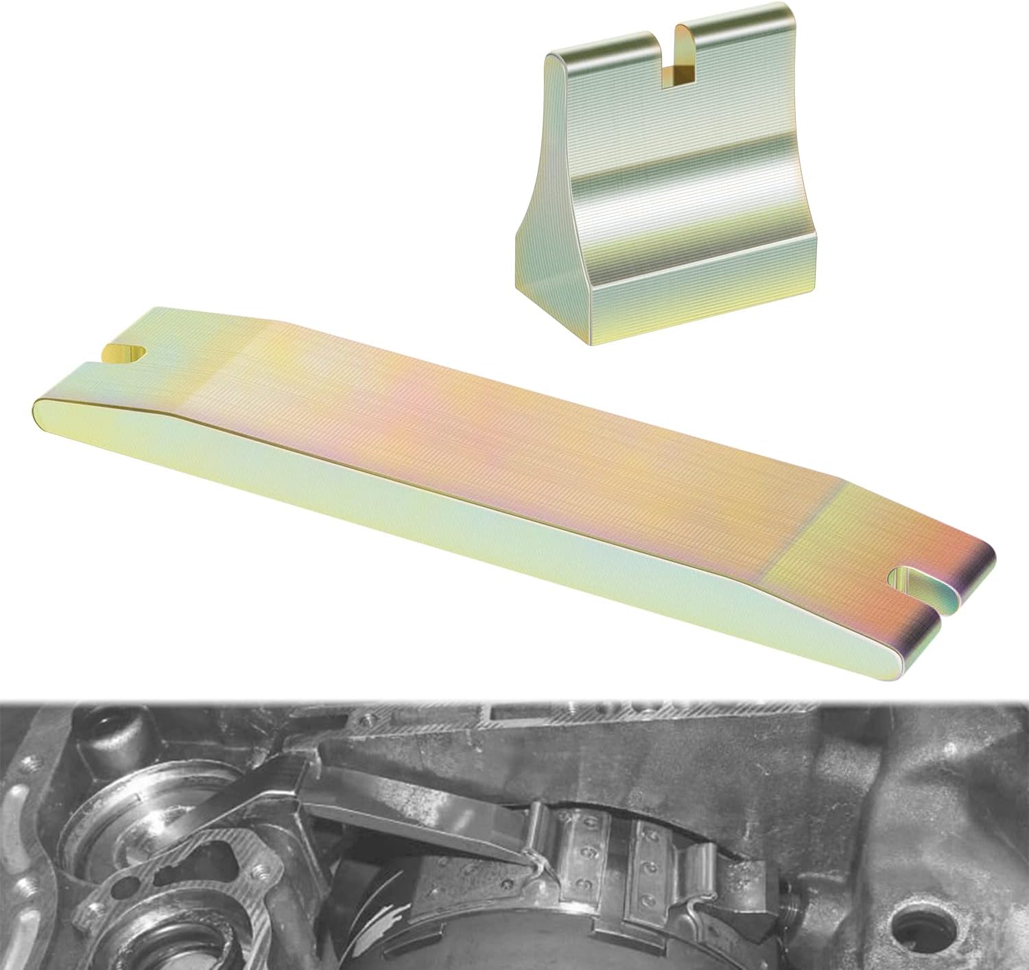
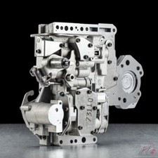
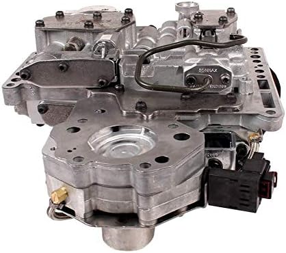
Split the complaint before you touch anything
Ask the driver four questions, because each answer sends you down a different circuit:
- Harsh in every gear, all the time, hot or cold. Line pressure is high across the board. Think throttle pressure or a pressure regulator that cannot balance.
- Harsh only since a recent rebuild or valve body swap. Assume mismatched parts until you prove otherwise. This one has a documented signature.
- Delayed engagement into Drive or Reverse, worst on the first start of the day, better once it is warm. That is drain-back and bore wear, not clutch wear.
- Delayed or wrong-gear starts with a check engine light. Now you are in the governor pressure system or a failsafe strategy, and the codes will narrow it fast.
Before any of that, confirm the fluid. These units require ATF+4, and nothing else is an acceptable substitute; the clutch and band friction characteristics are calibrated to it. Fluid that is dark, smells burnt, or reads low on a hot, level, engine-running check will produce every symptom on the list above and make your pressure readings meaningless.
The pressure test that names the part
Two gauges, because the range on this transmission is enormous. Line pressure comes off the accumulator port on the right side of the case with a 100 psi gauge; Reverse gets checked at the rear servo port with a 300 psi gauge. Per the ATSG service information for the 46RE/47RE/48RE family, a healthy unit reads:
| Range | Idle | Stall | Port and gauge |
|---|---|---|---|
| Drive, 1st gear | 54-60 psi | 90-96 psi | Accumulator, 100 psi gauge |
| Reverse | 145-175 psi | 230-280 psi | Rear servo, 300 psi gauge |
ATRA publishes a slightly different and very useful version of the same test taken at the forward clutch tap: 55-70 psi at idle in Drive, and 105-110 psi with maximum TV pressure in Drive at 1200 rpm. That second number is the one that matters for a harsh-shift complaint. If max line pressure comes in above 150 psi, stop testing electrical parts. You have a hydraulic problem, and there is a specific one to go look for.
While the gauges are on it, run ATRA's companion check. Put a second gauge on the servo release port alongside the forward clutch tap, unplug the solenoid harness, put the lever in Drive, and hold 1200 rpm. The two readings should be within 5 psi of each other. If third clutch tap pressure is considerably lower, the direct clutch piston or drum has failed and no amount of valve body work will fix the shift quality. Before condemning the drum, verify the #3 check ball is present and 11/32 in. in diameter, and inspect the large sealing rings on the front band servo and servo cover.
Transmission line pressure test gauge kit, 500 psi with adapters
You cannot do this job with one gauge. Reverse stall on a 48RE can hit 280 psi, which pegs a 100 psi gauge and tells you nothing, and the accumulator, servo and governor ports do not share a thread. $43.99, shipped from the USA.
View the gauge kit →Harsh path 1: the TTVA parked in high TV
Starting with model year 2005, Dodge trucks with the 5.9L Cummins and the 48RE dropped the throttle valve cable and got an electronically controlled Transmission Throttle Valve Actuator, or TTVA. It bolts to the case above the throttle valve shaft and drives the throttle valve directly through a D-shaped opening in the bottom of its shaft. Inside is a DC motor and two potentiometers reporting to the ECM. Gas trucks and 2003-2004 diesels kept the cable.
Here is the mechanism behind most harsh-shift complaints on an 05-07 truck, and it is the single most useful thing on this page. ATSG notes that several of the TTVA codes cause the ECM to shut off voltage to the actuator entirely, which leaves the TTVA motor position in high TV mode. Maximum throttle pressure, all the time, regardless of what your right foot is doing. Every shift bangs, line pressure reads high, and the transmission is doing exactly what it was told to do. Chasing that as a mechanical shift-quality problem is wasted work. Pull codes first.
| DTC | Definition |
|---|---|
| P1749 | Transmission Throttle Valve Position Sensor Circuit Low |
| P1750 | Transmission Throttle Valve Position Sensor Circuit High |
| P1751 | Transmission Throttle Valve Position Minimum Range Performance |
| P1752 | Transmission Throttle Valve Span Performance |
| P1753 | Transmission Throttle Valve Mechanical Performance |
| P1754 | Transmission Throttle Valve Actuator Stuck |
| P1755 | Transmission Throttle Valve Control Circuit |
There are no adjustments on the TTVA itself, but it must be initialized any time it is removed or replaced. Turn the ignition on with the engine not running and leave it for 30 seconds while the ECM runs its internal calibration and finds the current zero position. It repeats that calibration on every key cycle. During calibration the ECM is looking for at least 48 degrees of movement from minimum to maximum span, plus a minimum range value.
And this is the trap that catches good builders. Both of those calibration parameters are affected by the throttle shaft adjustment bolt on the pressure regulator spring retaining bracket. Per Sonnax, the distance from the bracket to the inside edge of the adjustment bolt head should be.905 in. Some of the older cable-activated throttle valve brackets have as little as .820 in. Put a cable-type bracket into a TTVA-equipped unit without resetting that adjustment and the TV shaft cannot travel far enough to satisfy calibration, so you set P1751, P1752, or both. Measure it on the bench, every time, before the valve body goes back in.
If the codes are not conclusive, verify the actuator with a meter. ATSG's observed values from a working truck:
| Signal | Closed throttle | Wide open throttle |
|---|---|---|
| TTVA position sensor | 3.78 V | 0.73 V |
| TTVA motor (+) | 2.0-2.5 V | 0-0.70 V |
| Accelerator pedal position sensor 1 | 0.45 V / 2% | 4.56 V / 96% |
| Accelerator pedal position sensor 2 | 0.24 V / 3% | 2.29 V / 97% |
Note that the position sensor runs backwards from what you would guess: high voltage at closed throttle, low at wide open. On 2005 diesels you backprobe terminal 35 at the ECM C1 60-way connector; on 2006-up it moved to terminal 27 at the ECM C2 50-way. Ground the black lead somewhere real, not on a painted bracket. One more note on parts: if the case has to be replaced on a TTVA truck, it has to be a 2005-or-later case, because the earlier castings do not have the two bosses the actuator bolts to.
There is a quiet failure mode here too. The TTVA is an open-loop mechanical calculation. As ATRA's GEARS magazine describes it, the computer moves the transmission throttle lever a specific distance relative to engine throttle and load, but there is no direct feedback on the resulting pressure. So when the throttle valve bore in the valve body wears, actual pressure for a commanded position is wrong, and you get early or late shifts with a healthy actuator and no codes at all. That makes TV bore wear the cause behind a lot of shift-timing complaints nobody can find. The same article names the four bores that wear worst on RE valve bodies: the throttle valve bore, the switch valve bore, the 1-2 and 2-3 governor plugs, and the line pressure plug and sleeve. On a shift-timing concern, inspect the TV bore and both governor plugs together, because they work as a set.
Harsh path 2: the wrong separator plate
If the harsh shifts showed up right after an overhaul, this is your first suspect and it has a fingerprint. ATRA documents 2003-and-later 48RE units complaining of harsh shifts and sudden loss of third or Reverse after overhaul, caused by mismatched valve body components. The 47RE and 48RE valve bodies look nearly identical, 48RE cores are hard to find, and 47RE parts end up in 48RE units constantly.
The difference is a hole. Install a 47RE separator plate on a 48RE valve body and you shut off all pressure regulator balance oil in Reverse, which creates extremely high line pressure in Reverse. That same missing balance hole also reduces the balance area on the regulator valve in the forward ranges, and that is exactly where the high line pressure and firm shifts come from. Pull the plate and look for the balance hole next to the filter location, and for an extra hole over the #2 check ball location that the 48RE plate does not use. High pressure from this mistake will go on to fail the direct clutch piston or drum, so it is worth catching before the comeback.
There is a second reason not to swap valve bodies casually. Writing in Transmission Digest, Sonnax TASC Force member Jim Dial laid out the pressure-curve difference: on a 46/47RE, converter clutch or overdrive apply oil moves the boost valve to exhaust one reduction point, raising line pressure roughly 10-15 psi in lockup and fourth. On a 48RE the same oil exhausts two reduction points for about 22-28 psi of rise, and with no reducing pressure at that second point the throttle pressure plug raises line faster as well. That extra clamping force is not optional behind a Cummins. Put a 46/47RE body in a 48RE and it drives fine at first, then comes back with a burned converter clutch or overdrive clutch.
Harsh path 3: governor pressure and the failsafe
Because first through third are governor-shifted, a governor fault reads as harsh shifts, shuttle shifts or a wrong-gear start rather than as an electrical complaint. The solenoid is a duty-cycle unit fed line pressure in any forward range, and it works inversely: one amp produces 0 psi of governor pressure, zero amps sets maximum. Resistance is roughly 3 to 5 ohms.
That inverse behavior gives you a free test. Unplug the case connector, put the selector in Drive, and read governor pressure at idle. It should reach approximately 60 psi, because the solenoid is fed rear (forward) clutch oil. If it stays low with the connector unplugged, the fault is internal: a bad solenoid, a clogged screen on the solenoid inlet port, or a damaged or misinstalled overdrive piston support to case gasket.
Diesel trucks run a different governor curve than gas trucks, and mistaking one for the other sends you chasing a fault that is not there. On a gas truck governor pressure tracks road speed roughly one to one. On a diesel it starts doubling road speed above about 20 mph, specifically to prevent 4-2 and 3-2 kickdowns that would overspeed the engine:
| MPH | 0 | 10 | 20 | 30 | 40 | 50 | 60 |
|---|---|---|---|---|---|---|---|
| Gas, governor psi | 0 | 10 | 20 | 30 | 40 | 50 | 60 |
| Diesel, governor psi | 0 | 8 | 38 | 60 | 65 | 68 | 70 |
On the scan tool, compare Governor Pressure Desired against Governor Pressure Actual. They should match up to about 35-40 mph. Above that the solenoid is essentially shut off, and desired will commonly read north of 100 psi while actual does not follow, because the solenoid is fed forward clutch pressure and at light throttle that is well under 100 psi. That divergence at highway speed is normal; divergence below 35 mph is not, and that is the range governing first through third. Always confirm with a mechanical gauge on the governor tap, because the transducer is a passive reporter and a failed one will hand the computer a number that is simply false. For the full solenoid and transducer breakdown, see our 48RE governor pressure solenoid write-up.
The delayed engagement side
Delayed engagement is a pressure-loss story, and on a 48RE it lives in a short list of bores. Sonnax's vacuum test guide for this unit maps the symptoms straight onto the valves:
- Pressure regulator valve. Delayed engagement, pressure regulator buzz, lube failures, converter bushing failure. Sonnax addresses it with kits 22771A-02K or 22771A-16K.
- Four-spool switch valve. Delayed engagement, lockup shudder, no cooler flow in Park, overheated converter, converter bushing failure. Kit 22771-14K.
- Line pressure plug and sleeve. Reverse slip, poor line pressure control, poor forward and Reverse engagement, poor cooler charge at idle. Kit 22771A-19K.
- Throttle valve. Shift timing concerns, throttle buzz, poor kickdown, 3-2 oversensitive. Kits 22771-03K or 22771-04K.
Notice how many of those repeat "converter bushing failure" and "no cooler flow in Park." That is the tell. A cold-morning delay that clears up after a few seconds and gets shorter as the truck warms is usually the converter draining back overnight through a leaking circuit, and the pressure regulator and switch valve bores are the usual leak paths. Vacuum testing the valve body on the bench finds it in minutes; a low vacuum reading at the test location means the bore is worn. Guessing at it means buying a converter you did not need.
Do not skip the boring causes on a delayed-engagement complaint either: low fluid, a collapsing or clogged filter, and a pan gasket leaking air into the pickup will all do the same thing, and they cost nothing to rule out.
Set the mechanical adjustments before you blame anything
Band adjustment affects apply feel directly, and on an RE unit the numbers are model-specific. Per the ATSG procedure, the front (kickdown) band: loosen the locknut, torque the adjusting screw to 8 N·m (72 in-lb), then back it off exactly 1-3/4 turns on a 48RE diesel or 1-1/2 turns on a 48RE V-10 gas, then hold the screw and torque the locknut to 41 N·m (30 ft-lb). For reference, a 47RE backs off 1-7/8 turns and a 46RE 2-7/8, which is another way people get shift feel wrong after mixing parts.
The rear (low and reverse) band: same 8 N·m (72 in-lb) on the adjusting screw, then back off exactly 3 turns on a 48RE, and torque the locknut to 34 N·m (25 ft-lb). While you are in the pan, valve body retaining bolts go to 12 N·m (100 in-lb), the filter screws to 4 N·m (35 in-lb), and the pan bolts to 13.6 N·m (120 in-lb).
Last, the line pressure adjusting screw, because someone has almost certainly been in there. Measure from the valve body to the inner edge of the adjusting screw flange with a steel scale; it should be 33.4 mm, or 1-5/16 in. Counter-clockwise moves the flange in and raises line pressure, clockwise lowers it, and one full turn changes line pressure about 2 psi. That is the entire authority of that screw, which is worth knowing in both directions: it will not fix a 40 psi problem, and someone cranking on it to chase a slip is a plausible reason a truck now shifts harsh. Set it to spec, then verify with the gauge rather than trusting the dimension, since manufacturing tolerance means the factory number is approximate.
An order of operations that converges
- Check fluid level, color and smell. ATF+4 only. Bad fluid invalidates everything below it.
- Pull codes. P1749-P1755 on an 05-07 diesel explains a harsh shift by itself, because the failsafe parks the TTVA in high TV.
- Pressure test. 54-60 psi idle in Drive, 90-96 stall at the accumulator; over 150 psi max line means look for the missing balance hole.
- Unplug the case connector in Drive at idle. Governor should climb to about 60 psi. If it does not, the fault is internal.
- Compare desired, actual and gauge governor pressure below 35 mph. Three readings, three different conclusions.
- On a delayed-engagement complaint, vacuum test the valve body at the pressure regulator, switch valve and line pressure sleeve before ordering a converter.
- Verify the separator plate and check balls match the unit any time the transmission has been apart before.
- Set both bands and the line pressure screw to spec and retest before condemning clutches.
The pattern that ties this together: on a 48RE, harsh almost always means something is commanding or allowing too much pressure, and delayed almost always means something is leaking pressure away before it reaches an apply. Once you know which of the two you have, the list of parts that can do it is short, and every one of them has a number you can measure.
If you are ordering while the pan is down, keep ATF+4 on the shelf before you start, because a pressure test plus a band adjustment will cost you several quarts and there is no acceptable substitute to run in the meantime.
48RE valve body components, governor pressure solenoid and transducer kits, separator plates, filters and pan kits, band struts, master rebuild kits, coolers and pressure gauges — shipped fast from the USA.
Shop 48RE parts →Sources
- Sonnax — "48RE Transmission Throttle Valve Actuator Codes." Backs the 2005 switch from TV cable to TTVA on diesel 2500 and 3500 Ram trucks, the DC motor and two-potentiometer construction, the D-shaped shaft interface, the 30-second key-on initialization and per-key-cycle recalibration, the 48 degrees of minimum-to-maximum span the ECM looks for, the.905 in. bracket-to-adjustment-bolt-head dimension versus as little as.820 in. on some cable-type brackets, and the P1749 through P1755 code definitions. sonnax.com
- Sonnax — "Chrysler 48RE Vacuum Test Guide." Backs the symptom-to-valve mapping used in the delayed engagement section: pressure regulator valve (delayed engagement, pressure regulator buzz, lube failures, converter bushing failure, kits 22771A-02K and 22771A-16K), the four-spool switch valve (delayed engagement, lockup shudder, no cooler flow in Park, overheated converter, kit 22771-14K), the line pressure plug and sleeve (Reverse slip, poor line pressure control, poor forward and Reverse engagement, poor cooler charge at idle, kit 22771A-19K), and the throttle valve (shift timing concerns, throttle buzz, poor kickdown, kits 22771-03K and 22771-04K), plus the principle that a low vacuum reading at a test location indicates bore wear. sonnax.com
- ATSG — 46RE, 47RE, 48RE Technical Service Information (PDF). Backs the line pressure specification chart (Drive 1st 54-60 psi at idle and 90-96 psi at stall at the accumulator port with a 100 psi gauge, Reverse 145-175 psi at idle and 230-280 psi at stall at the rear servo port with a 300 psi gauge), the ATF+4 fluid requirement, the TTVA description and 2005-or-later case requirement, the note that some TTVA codes cause the ECM to shut off actuator voltage and leave the motor in high TV mode, the observed TTVA position sensor voltages of 3.78 V closed throttle to 0.73 V wide open with motor and APP sensor values and their ECM connector terminals, the governor solenoid inverse current relationship and 3 to 5 ohm resistance, the approximately 60 psi governor reading with the case connector unplugged in Drive at idle, the transducer output of roughly 0.60 V at 0 psi to 3.0 V at 60 psi, the gas and diesel governor pressure versus road speed charts, the desired-versus-actual guidance up to 35-40 mph, the wrong-gear-start diagnostic sequence with the 0 psi, 7-12 psi, 0.66 V and 8.30 V decision points, the front and rear band adjustment torques and back-off turns by model, the valve body, filter and pan torque values, and the 33.4 mm line pressure adjusting screw dimension at about 2 psi per turn. ATSG manual (PDF)
- ATRA — "48RE Units: Slips or No 3rd and Reverse, High Line Pressure" (2013 technical bulletin, PDF). Backs the post-overhaul harsh shift signature: 2003-and-later 48RE units with harsh shifts and sudden loss of third or Reverse caused by mismatched valve body components, the forward clutch tap test values of 55-70 psi at idle in Drive and 105-110 psi at maximum TV pressure at 1200 rpm, the 150 psi threshold that points to a missing separator plate balance hole next to the filter location, the extra hole over the #2 check ball location on the 47RE plate, the explanation that the missing balance hole shuts off pressure regulator balance oil in Reverse and reduces regulator balance area in forward ranges, the resulting direct clutch piston or drum failure, the 5 psi tolerance between the forward clutch and servo release gauges, and the 11/32 in. #3 check ball. atracom.blob.core.windows.net (PDF)
- GEARS Magazine (ATRA) — "Bringing it Back to Life: A Logical Approach to the RE Valve Body," Keith Clark. Backs the four bores that wear worst on RE valve bodies (throttle valve bore, switch valve bore, the 1-2 and 2-3 governor plugs, and the line pressure plug and sleeve), the instruction to inspect the throttle valve bore together with both governor plugs when diagnosing a shift-timing concern, and the key point that the TTVA is an open-loop mechanical calculation with no direct feedback on resulting pressure, so a worn throttle bore produces incorrect pressure for the commanded position and causes early or late shifts. gearsmagazine.com
- Transmission Digest — "Dodge 48RE Hydraulic Features Revealed," Jim Dial, Sonnax TASC Force. Backs the pressure-curve difference between valve bodies: the 46/47RE boost valve exhausts one reduction point for about 10-15 psi of line rise in lockup or fourth, while the 48RE exhausts two reduction points for about 22-28 psi and allows the throttle pressure plug to raise line pressure at a quicker rate, plus the resulting torque converter clutch and overdrive clutch failures when a 46/47RE valve body is installed in a 48RE. transmissiondigest.com