When a 6R140 starts in what feels like second, won't upshift past fifth, and throws a speed sensor code, most owners go straight to ordering a sensor. Sometimes that is the fix. On this unit, though, the sensor is often the last thing wrong. The internal harness, the case connector and the shared sensor feed fail more often than the sensor heads, and the whole job requires dropping the pan and, for the turbine sensor, pulling the valve body. Get the diagnosis right before the truck goes up on the lift.
This guide covers what the two speed sensors on the 6R140 actually do, which codes and symptoms point at which one, how to prove a sensor bad with a scan tool and a scope before you open the pan, and the harness failure that GEARS Magazine calls a common area of concern on this unit. Sources are listed at the bottom.

Two sensors, not three
The 6R140 (TorqShift 6) runs two speed sensors: a turbine shaft speed (TSS) sensor and an output shaft speed (OSS) sensor. That trips up people coming from the 10R140, which Sonnax documents with four Hall effect speed sensors (TSS, two intermediate shaft sensors and OSS). On the 6R140 there is no intermediate shaft sensor to worry about. If a parts catalog is trying to sell you an "ISS" for a 6R140, check what it actually fits.
Wayne Colonna's TorqShift 6 technical write-up in Vehicle Service Pros lays out the circuits, and it is worth having in front of you when you back-probe:
| Item | Turbine shaft speed (TSS) | Output shaft speed (OSS) |
|---|---|---|
| Sensor type | Hall effect | Hall effect |
| Signal | 0-5 V pulsed (square wave) | 0-5 V pulsed (square wave) |
| 19-pin case connector | Pin 11 | Pin 17 |
| Gas (PCM, 50-pin C175T) | PCM pin 1 | PCM pin 14 |
| Diesel (TCM, 60-pin C1750) | TCM pin 50 | TCM pin 51 |
| Power and ground | Shared with each other and with the transmission range (TR) sensor | |
Two things in that table matter for diagnosis. First, gas trucks (6.2L) run the transmission off the PCM, and the 6.7L diesel uses a separate TCM. Ford Component Sales lists the same split. Pin numbers are different, so use the right column. Second, both speed sensors share power and ground with the TR sensor. If you have a TSS code, an OSS code and a range sensor complaint all at once, you are almost certainly looking at a feed, ground, harness or connector problem, not three failed sensors.
How the 6R140 differs from the 6R80
On the 6R80, GEARS Magazine's David Chalker describes the early mechatronic unit housing the OSS, TSS, fluid temperature sensor and range sensor together. That is why 6R80 speed sensor jobs so often turn into a lead frame or mechatronic replacement. The 6R140 uses discrete sensors wired into an internal harness and routed through the 19-pin pass-through case connector. That is good news for parts cost and bad news for troubleshooting, because the harness between the sensor and the connector is its own failure point.
What each sensor does for the module
The module never measures gear ratio directly. It divides turbine speed by output speed and compares the result to the ratio it expects for the commanded gear. Using the Ford Component Sales ratios, here is what TSS should read with the OSS at 1,000 rpm:
| Gear | Ford ratio | Expected TSS at 1,000 rpm OSS |
|---|---|---|
| 1st | 3.974 | about 3,974 rpm |
| 2nd | 2.318 | about 2,318 rpm |
| 3rd | 1.516 | about 1,516 rpm |
| 4th | 1.149 | about 1,149 rpm |
| 5th | 0.858 | about 858 rpm |
| 6th | 0.674 | about 674 rpm |
| Reverse | 3.128 | about 3,128 rpm |
That calculated ratio is how the module confirms a shift finished, decides whether a clutch is slipping, and learns its shift adapts. Jim Dial at Sonnax, writing in Transmission Digest about 6R80 and 6R140 shift timing, puts it plainly: during a shift the PCM is looking for an rpm drop on the turbine speed sensor within a split second of the solenoid command. The TSS signal is the stopwatch for every shift. If it drops out or reads noisy, the module can't tell a good shift from a slipping clutch, and adaptive learning goes sideways.
The OSS gives the module road speed for the shift schedule and the denominator for every ratio calculation. Lose it and the module has no idea when to shift, or whether the ratio it sees is correct.
Symptoms of a bad 6R140 speed sensor
Stuck in fifth (starts off "in second")
This is the big one. Colonna quotes the Ford strategy: if an electronic, hydraulic or mechanical malfunction occurs, the PCM or TCM turns off all current to the transmission, leaving only fifth and reverse, with the converter clutch unlocked. A hard speed sensor fault is exactly the kind of electronic fault that triggers it. Because fifth is a 0.858 overdrive ratio, the truck pulls away like a slug and owners describe it as starting in second or third. Key off and back on often restores normal shifting until the fault returns.
Intermittent, heat-related codes
GEARS Magazine's 6R140 problems roundup says speed sensor codes are common on this unit, but they can be operating temperature related or intermittent and difficult to duplicate. A truck that shifts fine cold and drops into failsafe after 30 minutes of towing is a classic pattern. Heat expands the harness and the sensor body, and a marginal connection opens.
Harsh or flared shifts with no code
A TSS signal that is noisy but not dead enough to set a code corrupts the shift timing Dial describes. The module sees the rpm drop late or early, adapts the wrong way, and you get a flare on one shift and a bind-up on the next.
Gear ratio and converter codes riding along
Because every ratio depends on both sensors, a bad speed signal can set ratio codes (P0731-P0736) or converter slip codes that look like a mechanical failure. Always clear up any speed sensor code before you condemn clutches based on a ratio code.
Codes to know
- P0715 - Input/turbine speed sensor circuit malfunction (TSS)
- P0717 - Input/turbine speed sensor circuit no signal (TSS)
- P0720 - Output speed sensor circuit malfunction (OSS)
- P0722 - Output speed sensor circuit no signal (OSS)
- P1900 / P1901 - Ford codes for OSS and TSS circuit intermittent
- P0731-P0736 - Incorrect gear ratio, first through sixth; often a consequence, not the cause
The intermittent codes are the ones that point hardest at the harness. A dead sensor usually sets a no-signal code and stays dead. A sensor circuit that comes and goes is more often a splice, a pin or the connector.
How to diagnose it before you drop the pan
- Fluid and connector first. Check the level hot with MERCON LV. Unplug the 19-pin case connector and look for fluid inside it, bent or pushed-back pins and green corrosion. Fluid wicking up into the connector will cause intermittent signal loss that no sensor replacement will fix.
- Read the codes and freeze frame. Note temperature, speed and gear when the code set. A code that only sets above normal operating temperature points toward the harness or a heat-sensitive sensor.
- Log the PIDs on a road test. Record engine rpm, TSS rpm, OSS rpm, commanded gear, and transmission fluid temperature. Sonnax's speed sensor guide for the later 10R family makes the case for doing this with scan data: engine rpm, each sensor rpm, commanded gear and measured ratio together tell you which signal is lying. The same method works on the 6R140.
- Do the math. In a steady gear, TSS divided by OSS should land on the ratio in the table above. With the converter clutch locked, TSS should match engine rpm. If TSS matches engine rpm with the TCC locked but the ratio is wrong, suspect OSS. If OSS tracks road speed smoothly but TSS drops to zero or spikes, suspect TSS or its circuit.
- Watch for dropouts. A sensor rpm that drops to zero for an instant, then recovers, is a wiring or connection fault until proven otherwise. Wiggle the harness at the case connector and along the frame rail while watching live data.
- Scope the signal. Back-probe the TSS at case connector pin 11 and the OSS at pin 17 (or the module pins in the table). You want a clean 0-5 V square wave whose frequency rises with speed. Rounded edges, missing pulses or a signal that flattens as the unit warms up all show what a meter can't.
- Check the shared feed. Since both speed sensors and the TR sensor share power and ground, measure the feed and ground at the connector with the key on. A weak feed or open ground takes down all three at once.
The internal harness problem
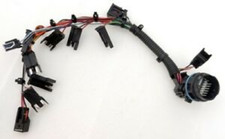
This is the failure that catches good technicians on the 6R140. GEARS Magazine reports that splices inside the internal wiring harness can become compromised and fail, causing intermittent circuit continuity. The sensor heads test fine on the bench, the case connector looks clean, and the code keeps coming back. The fault is in a crimp buried in the harness under the valve body.
Two practical points from the same article. The recommended repair is to clean and repair the existing splice with solder and oil-resistant shrink tube for a permanent repair. And the new OEM harness has splices like the original, so a new harness is not automatically a better part than a properly soldered original. If you are replacing the harness, inspect the new one before it goes in, and solder any splice that looks suspect.
To test it on the bench, run continuity from each sensor pin to its case connector pin while flexing the harness along its length, and do it again after warming the harness with a heat gun. An intermittent splice will often only open under heat and movement.
Replacing the sensors
Access is the reason to get the diagnosis right:
- OSS: sits inside the case at the rear and is reached by dropping the pan. On a 6R140 that means draining a unit that holds about 4 gallons of MERCON LV total, per Ford Component Sales, though a pan drop drains only part of it.
- TSS: sits behind the main control valve body, toward the front on the driver side. Owners on Ford Truck Enthusiasts describe having to pull the pan and the valve body to reach it. Treat that as field experience, and confirm the procedure in the Ford workshop manual for your year before you start.
A few rules that save comebacks:
- Clean the sensor tip and look for metal. Hall effect sensors are magnetic, and a fuzzy tip packed with clutch and gear debris can distort the signal. Heavy debris on the tip also tells you the unit has a bigger problem.
- Replace the O-ring and torque the retaining bolt to the manual spec. A loose sensor changes the air gap and gives a weak or intermittent signal.
- If the valve body comes off, keep the solenoids in their original positions. 6R140 solenoids are banded, and a mixed-up solenoid is a new shift problem you just created.
- Inspect every harness splice you can see while it is exposed. This is the cheapest time to fix the problem GEARS describes.
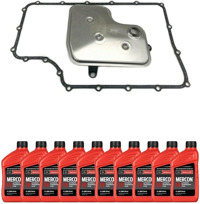
- Install a new filter and pan gasket, refill with MERCON LV, and check the level hot per Ford's procedure.
- Clear codes, reset adaptive tables with a capable scan tool and road test through all six gears with the PIDs logged. Confirm TSS/OSS ratios in each gear before handing the truck back.
Preventing a repeat
Keep fluid temperature under Ford's 250°F continuous rating, since heat is what makes marginal splices and sensors fail. Keep the case connector dry and sealed. And if the sensor tips come out covered in metal, stop and find out why. A speed sensor code can be the first sign of a mechanical failure inside the unit.
6R140 filter kit with pan gasket
Every speed sensor job on this unit starts with dropping the pan, and the TSS job means pulling the valve body too. Don't reuse the old filter and gasket. This kit fits the 2011-up Super Duty TorqShift 6. Sold by our sister store, CoreTransmissionParts.
Shop the part for this fix →Looking for sensors for other units? The sensors collection covers speed sensors across most common transmissions.
Need parts for this job?
Our 6R140 parts page carries the internal wiring harness, filter and pan gasket kits, MERCON LV service kits and complete valve bodies. Checkout is on site.
FAQ
What are the symptoms of a bad 6R140 speed sensor?
The most common is the transmission dropping into failsafe, where it only has fifth and reverse, so the truck feels like it starts in second or third. You may also see harsh or flared shifts, a stored P0715, P0717, P0720 or P0722, and gear ratio codes riding along. Heat-related, intermittent faults are common on this unit.
How many speed sensors does a 6R140 have?
Two: a turbine shaft speed (TSS) sensor and an output shaft speed (OSS) sensor, both Hall effect types with a 0-5 volt pulsed signal. There is no intermediate shaft speed sensor on the 6R140. The later 10R140 is the Ford unit with four speed sensors.
Where is the 6R140 turbine speed sensor?
It sits inside the case behind the main control valve body, toward the front on the driver side, so the pan and valve body have to come off to reach it. The output speed sensor is also internal and is reached by dropping the pan. Confirm the procedure in the Ford workshop manual for your year.
Can a wiring problem cause a 6R140 speed sensor code?
Yes, and it is common. GEARS Magazine reports that splices inside the 6R140 internal wiring harness can fail and cause intermittent continuity. Both speed sensors also share power and ground with the range sensor, so a feed or ground fault can knock out several signals at once.
Related guides
- 6R140 Limp Mode Causes
- 6R140 Won't Shift Into Overdrive
- 6R140 Shift Solenoid Symptoms and Replacement
- 6R140 Filter and Pan Service
- 6R80 P0715 Fix
Sources
- Wayne Colonna, "Introducing Ford's TorqShift 6 Transmission," Vehicle Service Pros. Backs the Hall effect TSS and OSS, the 0-5 V pulsed signals, case connector pins 11 and 17, PCM pins 1 and 14, TCM pins 50 and 51, shared power and ground with the TR sensor, the 19-pin case connector and 50/60-pin module connectors, and the fifth-and-reverse failsafe with the TCC unlocked. vehicleservicepros.com
- Ford Component Sales, LLC, Ford 6R140 6-Speed Automatic Transmission Technical Specifications. Backs the gear ratios used in the TSS/OSS table, PCM control on gas and TCM control on diesel, MERCON LV, the 4-gallon capacity and the 250°F continuous rating. fordcomponentsalesllc.com (PDF)
- GEARS Magazine (ATRA), "Problems and Fixes! Revisiting the 6R140 Transmission." Backs speed sensor codes being common, temperature-related and intermittent, internal harness splice failures, the solder and oil-resistant shrink repair, and new OEM harnesses having splices too. gearsmagazine.com
- Jim Dial (Sonnax), "Ford 6R80 & 6R140: Troubleshooting timing-related shift issues," Transmission Digest. Backs the PCM watching for a TSS rpm drop within a split second of solenoid command, and banded solenoids. transmissiondigest.com
- Jim Mobley, Sonnax, "Diagnosing Ford 10R60, 10R80, 10R140 Series Speed Sensor Issues." Backs the four-sensor 10R layout used for contrast and the scan-data method of comparing engine rpm, sensor rpm, commanded gear and measured ratio. sonnax.com
- David Chalker, "Updates to the Ford 6R80," GEARS Magazine. Backs the 6R80 mechatronic unit housing the OSS, TSS, TFT and TR sensor, used for the 6R80 comparison. gearsmagazine.com
Field note (not counted as a source): owner reports on sensor access, Ford Truck Enthusiasts forum.