A GM 6T70 or 6T75 with a speed sensor problem usually shows up one of two ways: it drops into a fixed gear with a check engine light and a harsh bang into Drive, or it throws a code only in certain gears and the shop replaces the sensor twice before anyone looks inside the drum. Both units use two hall-effect sensors, an input speed sensor (ISS) and an output speed sensor (OSS), and the TCM leans on them for almost everything it does. Lose either signal and the TCM stops trusting its own math.
This guide walks through what each sensor actually reads, the exact conditions GM uses to set P0716, P0717, P0722 and P0723, the symptoms you get when they set, and the test sequence that separates a bad sensor from a bad TCM, a bad reluctor or a failed retainer ring inside the 3-5-Reverse drum. The specs come from GM service information for the 6T70/6T75, GM bulletins hosted by NHTSA and an ATRA case study, listed in the Sources at the end.

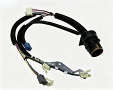

What the ISS and OSS read on a 6T70
Per GM service information, both sensors are hall-effect types that receive an 8.3-9.3 volt supply from the TCM and return a frequency signal. They plug into the control solenoid valve assembly (the TEHCM, which houses the TCM) through short internal harnesses: the ISS at connector X3 and the OSS at connector X4.
- Input speed sensor (ISS). Mounts to the case cover and reads a reluctor ring attached to the 4-5-6 clutch and 3-5-Reverse clutch housing. That housing turns with the input shaft, so the ISS is effectively turbine speed.
- Output speed sensor (OSS). Mounts under the control valve body and faces the front differential transfer drive gear. It reads output speed before the final drive.
GM states the TCM uses both signals to determine line pressure, shift patterns, torque converter clutch (TCC) slip speed and gear ratio. That list is why a speed sensor fault feels like a transmission failure. The TCM calculates gear ratio as ISS divided by OSS and compares it to what it commanded. When one signal drops out, the ratio looks like a slipping clutch, and the TCM protects the unit the only way it can.
The ratio check you can do on the scan tool
GM publishes the 6T70/6T75 ratios as 4.484 in 1st, 2.872 in 2nd, 1.842 in 3rd, 1.414 in 4th, 1.000 in 5th, 0.742 in 6th and 2.88 in Reverse, with effective final drive ratios of 2.77 or 3.16. Graph Transmission ISS and Transmission OSS together on a road test. In 3rd with the OSS at 1,000 RPM, the ISS should sit near 1,842 RPM. A clean ratio in every gear except one, followed by an ISS that falls toward zero in that gear, points you inside the unit, not at the sensor. More on that below.
Symptoms of a failing 6T70 speed sensor
When P0716, P0717, P0722 or P0723 sets, GM service information lists the same default action for all four: they are Type A codes, and the TCM freezes adaptive functions, turns off the high side driver, commands maximum line pressure, inhibits Tap Up/Down and manual shifting of forward gears, and limits the transmission to Reverse and 5th gear. The input codes also command the TCC off and disable neutral idle. Here is what the driver feels:
- Stuck in one gear (limp mode). The unit takes off in 5th, feels gutless from a stop and never shifts. Reverse still works. This is the single most common complaint.
- Harsh engagement into Drive and Reverse. With the high side driver off and line pressure at maximum, garage shifts hit hard.
- Higher cruise RPM and no converter lockup. With TCC commanded off, highway RPM climbs and fuel economy drops.
- Paddle or tap shift dead. Manual range selection of forward gears is inhibited.
- Intermittent flare or harsh shifts before the code. An ISS signal that drops briefly can corrupt shift adapts before it ever meets the code threshold, so shifts get erratic first and the light comes on later.
- Check engine light with the codes above. Because these are Type A codes, the light comes on the first time the fault is detected.
The exact set conditions for each code
Knowing the thresholds tells you what kind of signal loss you are chasing. From GM service information:
- P0716, Input Speed Sensor Performance. Runs with engine speed above 400 RPM for 5 seconds, ignition voltage at least 8.6 volts and vehicle speed of 10 km/h (6 mph) or more. Sets when input speed drops 1,350 RPM in 1.0 second and does not recover. That is a sudden drop, not a dead sensor.
- P0717, Input Speed Sensor Circuit No Signal. Runs at 16 km/h (10 mph) or more with engine torque of at least 50 N·m (37 lb-ft). Sets when input shaft speed stays below 50 RPM for 5.0 seconds. That is a flat-lined signal.
- P0722, Output Speed Sensor Circuit No Signal. Runs out of Park and Neutral with input speed of at least 1,000 RPM, throttle at 5 percent or more and engine torque of at least 35 N·m (26 lb-ft). Sets when output speed is 70 RPM or less for 4.0 seconds.
- P0723, Output Speed Sensor Circuit Intermittent. Sets when output speed has been at least 105 RPM and then drops more than 650 RPM without recovering for 1.5 seconds.
A P0716 or P0723 means the signal was there and then fell away. That pattern favors a mechanical cause: a loose or damaged reluctor, debris on the sensor tip or a sensor that is not seated. A P0717 or P0722 with the vehicle clearly moving favors a dead sensor, an open harness or a supply problem.
How to diagnose it: the GM test sequence
GM's procedure is short and it is in a specific order for a reason. Follow it and you will not buy a sensor you did not need.
Step 1: Check supply voltage status
Key on, and read the scan tool parameter ISS/OSS Supply Voltage. It should read OK. The ISS and OSS share this supply from the TCM, so if it reads Out of Range you have a supply circuit short or a TCM fault, and swapping a sensor will not fix it.
Step 2: Watch the live signal
For the ISS, idle in Park at normal operating temperature and vary engine speed. GM's normal range for Transmission ISS in Park is 500-5,800 RPM, and it should follow engine speed without dropping out. For the OSS, drive at 16-32 km/h (10-20 mph) and watch Transmission OSS, which has a normal range of 0-7,000 RPM. It should track vehicle speed smoothly. A shorted or open circuit reads 0 RPM on either one.
If both signals are clean and the code will not reset under its run conditions or freeze-frame conditions, GM tells you to stop and treat it as an intermittent. Do not tear into it.
Bench testing a pulled sensor
Do not condemn one of these sensors with a voltmeter on the signal wire. They are 2-wire active sensors that signal by switching current, not voltage. In GEARS Magazine's "Advanced Speed Sensors, Part 2," the example sensor switched between about 7 mA and 14 mA while the voltage change at the sensor was only about 20 mV. GEARS' fix is to put a 10-ohm resistor in series and scope the voltage drop across it while the target turns, which gives a clean square wave; the example shown was a 6T40 input speed sensor, the 6T70's smaller cousin with the same style of sensor.
Step 3: Test at the TEHCM
If the signal fails, the next checks happen with the control valve body cover off. Connect the vehicle harness to the 20-way X1 connector, disconnect the sensor lead (X3 for the ISS, X4 for the OSS) from the control solenoid valve assembly and check for 8.3-9.3 volts between terminal A and case ground with the key on. If it is not in range, GM calls for replacing the control solenoid valve assembly, because the supply comes from the TCM inside it.
Step 4: Prove the TCM input with a signal generator
GM's ISS/OSS input test uses an EL 38522 variable signal generator set to 5 volts, 300 Hz and 50 percent duty cycle, fed into the sensor signal terminal B on the TCM side. With the key on, the scan tool should show Transmission ISS at 495-505 RPM and Transmission OSS at 256-266 RPM. If the TCM reads the simulated signal correctly, the module is good and the problem is the sensor, its lead or what it is reading.
Step 5: Inspect what the sensor reads
Before a new sensor goes in, GM has you inspect the target. For the ISS, check the reluctor on the 4-5-6 and 3-5-Reverse clutch housing for damage or misalignment. For the OSS, inspect the transfer drive gear teeth and look for metallic debris on the sensor face. Only if all of that passes does GM call the sensor itself bad.
The failure that fools everyone: the ISS reluctor retainer
The ISS does not read a gear cut into a shaft. It reads a separate reluctor piece held to the 3-5-Reverse drum by a retainer ring. When that ring leaves its groove, the reluctor can still turn with the drum most of the time, so the signal looks fine in some gears and drops out in others.
GM documented this in service bulletin 16-NA-013 for 2016 model-year units: a no Reverse or no 3rd condition with an erratic input speed signal and P0716, P0717 and/or P0776. The stated cause is the input shaft speed sensor reluctor ring retainer ring out of its groove, and the repair replaces the retainer ring, the reluctor wheel, the 3-5-Reverse clutch piston and the 3-5-Reverse and 4-5-6 clutch housing. That is a drum repair, not a sensor repair.
ATRA's Keith Clark described the same mechanism in GEARS Magazine on the Ford 6F55, which shares its basic architecture with the GM 6T75 from the joint GM-Ford six-speed program. The shop saw the input signal fall to zero every time the unit reached 3rd or 5th, with P0717 setting. Two new sensors changed nothing, and the harness passed a wiggle test. Inside, the snap ring that held the cast retainer to the 3-5-Reverse drum had blown off. With the snap ring gone, apply pressure in the 3-5-Reverse circuit pushed the retainer against the end cover and stopped it, so the ISS saw nothing until the clutch released. The bad signal also corrupted the 3-5-Reverse adapt, which caused harsh engagements into 3rd, 5th and Reverse.
The diagnostic tell is simple once you know it: the ISS drops out only when the 3-5-Reverse clutch is applied, which is 3rd, 5th and Reverse. A dead sensor or bad wire does not care what gear you are in.
Debris on the sensor tip
Both sensors are magnetic, so they collect ferrous material from the fluid. GM's P0722/P0723 diagnostic aids call out metallic debris on the face of the OSS as a cause of a speed sensor malfunction. A fuzzy sensor tip is also a message about the rest of the unit. If you pull a sensor packed with metal, find out where the metal came from before you put the vehicle back on the road, or the new sensor will be packed with it again soon.
Replacing the sensors: access and torque
Neither sensor is a bolt-on from outside the case. Per GM service information:
- ISS. Drain the fluid, remove the lower radiator air baffle, the left transmission mount and bracket, and the control valve body cover. GM specifies the DT-47734 speed sensor harness tether, clipped to the ISS connector locking tab before the old sensor comes out, so you can pull the new harness back through. The M6 x 25 bolt gets threadlocker and is torqued to 9 N·m (80 lb-in). Replace the ISS seal.
- OSS. Remove the control valve lower and upper body to reach it. The M6 x 25 bolt is torqued to 12 N·m (106 lb-in). GM notes that proper OSS bolt torque is critical to proper sensor operation, because the air gap to the transfer drive gear depends on it.
- After either job. GM calls for the Service Programming System procedure after internal repairs and for resetting the transmission adapts after all transmission repairs. Then road test so the TCM relearns.
Because the valve body comes out for the OSS, check the control solenoid valve assembly filter plate and the valve body for debris while you are in there. Refill with DEXRON-VI and set the level hot.
Sensor, TCM or hard parts: making the call
- Supply voltage Out of Range, or signal generator test fails: the TCM inside the control solenoid valve assembly is the problem.
- Supply OK, generator test passes, reluctor and gear look good, signal still dead: replace the sensor.
- ISS drops out only in 3rd, 5th and Reverse: reluctor retainer ring or 3-5-Reverse drum damage. Sensors will not fix it.
- OSS erratic with metal on the tip: clean or replace the sensor, then find the source of the metal.
6T70 input speed sensor at Core Transmission Parts →
6T70 Output Speed Sensor
If the OSS failed the live-data and generator tests with a clean transfer drive gear, this is the replacement. Torque it to 12 N·m. Looking for something else? Browse all 6T70 parts.
View the 6T70 OSS →Need parts for this job?
6T70 transmission control modules, internal wiring harnesses, magnetic drain plugs and rebuild parts, shipped from the USA.
Shop 6T70 parts →FAQ
What are the symptoms of a bad speed sensor on a 6T70?
The transmission usually goes into a default mode limited to Reverse and 5th gear, so it launches weak and never shifts. Garage shifts get harsh because the TCM commands maximum line pressure, the converter clutch stays off and tap shifting stops working. The check engine light comes on with P0716, P0717, P0722 or P0723.
Where is the input speed sensor on a 6T70?
The ISS mounts to the case cover inside the transmission and reads a reluctor on the 4-5-6 and 3-5-Reverse clutch housing. It plugs into the control solenoid valve assembly at connector X3. To reach it GM has you drain the fluid, remove the left mount and bracket and pull the control valve body cover.
Can you drive a 6T70 with a bad speed sensor?
It will usually still move in 5th gear and Reverse, which is the TCM's protection mode. Launches are slow, engagements are harsh and the converter clutch stays off, so it runs hotter and uses more fuel. Drive it only as far as the shop, because the underlying cause can be internal damage.
Why does my 6T70 keep setting P0717 after a new input speed sensor?
Check whether the ISS signal drops out only in 3rd, 5th and Reverse. That pattern points to the reluctor retainer ring on the 3-5-Reverse drum, which GM covered in bulletin 16-NA-013. The fix is the retainer, reluctor and drum parts, not another sensor. Also verify ISS/OSS supply voltage and run GM's signal generator test to rule out the TCM.
What is the torque spec for the 6T70 speed sensor bolts?
GM specifies 9 N·m (80 lb-in) with threadlocker for the input speed sensor bolt and 12 N·m (106 lb-in) for the output speed sensor bolt. Both are M6 x 25 bolts. GM notes that correct OSS bolt torque is critical to proper sensor operation.
Sources
- GM service information (Saab 9-4X, Automatic Transmission 6T70/6T75) — DTC P0716 or P0717. Backs the ISS description (hall effect, 8.3-9.3 V supply, reluctor on the 4-5-6 and 3-5-Reverse clutch housing, used for line pressure, shift patterns, TCC slip and gear ratio), the 500-5,800 RPM normal range, the P0716 and P0717 run and set conditions, the Type A default actions (Reverse and 5th only, TCC off, maximum line pressure), and the ordered circuit test and reluctor inspection. saabwisonline.com
- GM service information (6T70/6T75) — DTC P0722 or P0723. Backs the OSS description (faces the front differential transfer drive gear), the 0-7,000 RPM normal range, the P0722 and P0723 run and set conditions and default actions, the 10-20 mph verification drive, and the diagnostic aids on damaged drive gear teeth, metallic debris on the sensor face and critical OSS bolt torque. saabwisonline.com
- GM service information (6T70/6T75) — Control Solenoid Valve and TCM Assembly ISS/OSS Input Test, and Shift Solenoid Valve State and Gear Ratio. Back the EL 38522 signal generator settings (5 V, 300 Hz, 50 percent duty), the expected 495-505 RPM ISS and 256-266 RPM OSS readings, and the published gear ratios and final drive ratios. input test · gear ratio chart
- GM service information (6T70/6T75) — Input Speed Sensor Replacement and Output Speed Sensor Replacement. Back the ISS access steps, the DT-47734 harness tether, the threadlocked 9 N·m (80 lb-in) ISS bolt, the valve body removal for OSS access, the 12 N·m (106 lb-in) OSS bolt, and the SPS procedure after internal repair. ISS replacement · OSS replacement
- General Motors — Service Bulletin 16-NA-013, "No Reverse, No Third, DTC P0716, P0717, P0776," hosted by NHTSA. Backs the 2016 model-year condition with an erratic input speed signal, the cause (ISS reluctor ring retainer ring out of its groove), and the replacement of the retainer ring, reluctor wheel, 3-5-Reverse piston and 3-5-Reverse and 4-5-6 clutch housing. static.nhtsa.gov
- ATRA / GEARS Magazine — Keith Clark, "The Disappearing Input Speed Sensor Signal," April 2018. Backs the case of an ISS signal dropping to zero in 3rd and 5th with P0717, two replacement sensors that did not fix it, the blown snap ring on the cast retainer that serves as the ISS reluctor, the apply-pressure mechanism that stopped the retainer, and the harsh 3rd, 5th and Reverse from the corrupted adapt. gearsmagazine.com
- ATRA / GEARS Magazine — "Advanced Speed Sensors, Part 2." Backs 2-wire active sensors signaling by current change (about 7 mA to 14 mA in the example), the roughly 20 mV voltage change at the sensor, and the 10-ohm series resistor scope method shown on a 6T40 input speed sensor. gearsmagazine.com