A belt or chain CVT has no gears to change, so a "harsh shift" or "delayed shift" complaint is always describing something else. Most of the time it is a garage shift: the engagement when the driver pulls out of Park or Neutral into Drive or Reverse. The rest is a ratio-sweep event the module is handling badly, or on a Toyota, the mechanical handoff off the launch gear that customers hear as a clunk. Sorting which one you have is most of the job, and the garage shift path is where the codes, the specs and the money are.
First, know what normal looks like: the 2-to-3-second rule
Jatco went to real trouble to keep drive and reverse engagements soft, because a harsh engagement slams torque into the variator and can damage the pulley assembly. The side effect is a noticeable pause. Nissan bulletin NTB-10-147 states that a 2- to 3-second delay is normal operation, and that anything longer points to internal transmission issues; the same bulletin included a TCM re-flash to tighten the delay.
So before you sell a job: on a CVT2 (JF011E), a two-second pause into gear is the transmission working as designed. Wayne Colonna of ATSG put a boundary on it for the later units, which use a better engagement strategy. If a CVT7 or CVT8 takes longer than 3 seconds to engage, you know for certain you have a problem with the transmission or the software. That rule keeps you from re-flashing a healthy CVT2 and from waving off a sick CVT8.
How Jatco actually controls a garage shift
All three generations do the same job with different hardware, and you cannot diagnose this without knowing which one you have.
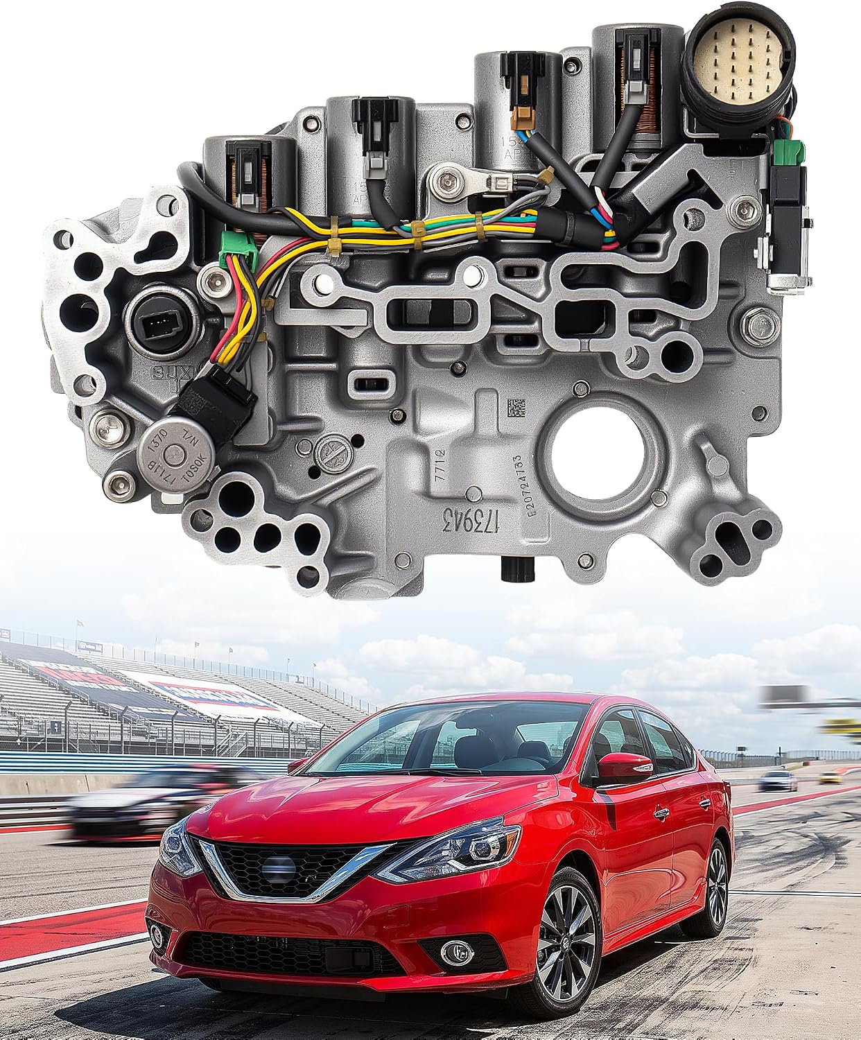
CVT2 (JF011E) — two solenoids, two valves, and check-balls
Above the manual valve, the reverse and forward clutch feeds each carry a double check-ball arrangement controlling both apply and release. Feeding the manual valve is the select switching valve, positioned by an on/off lock-up select switch solenoid. Energize that solenoid and the switching valve strokes, routing regulated pressure from the select control valve to the manual valve. The select control valve is itself regulated by the lock-up control solenoid, a normally-low PWM solenoid.
Note the series arrangement, because it is why this design is slow: PWM solenoid pressure has to pass through the select switching valve before it can influence the select control valve. Once it does, the select control valve feeds the manual valve a regulated pressure that ramps the clutch on. Pushed to its extreme, that same valve can block pressure to the manual valve entirely, giving you a no-move condition.
Once fully in gear, the lock-up select switch solenoid turns off and the switching valve closes: full line pressure now holds the clutch applied, and the PWM solenoid's output is re-routed to the lock-up control valve for converter clutch apply. One solenoid, two jobs, depending on where the switching valve sits. Shops report some success with a lighter select control valve spring to speed engagement.
CVT7 (JF015E) — direct PWM on the applying element
Completely different approach. The manual valve is supplied from the solenoid regulator valve. In Drive, feed oil at the manual valve routes to the low brake solenoid, a PWM solenoid that ramps the low brake on, and to the select relay valve, which feeds the high clutch/reverse brake (H&R) solenoid. In Reverse, that H&R solenoid (also PWM) ramps the reverse brake on. No long series path, so engagement is quicker than the CVT2.
CVT8 (JF016E / JF017E) — one select solenoid does it all
The CVT8 borrows the double check-ball layout from the CVT2 and the direct solenoid control from the CVT7. It uses a single select solenoid, fed regulated pressure from pilot valve A, and that PWM solenoid supplies the manual valve directly for both Drive and Reverse engagements. Because everything routes through one solenoid, that solenoid can also block all engagement, either as a failsafe function or when it fails.
Know the unit codes: CVT-8LT (JF016E) for four-cylinder, CVT-8HT (JF017E) for V6, behind 2.0L to 3.5L engines. Nissan calls them RE0F10D (code 3VX0A) and RE0F10E (3WX0A); Mitsubishi uses F1CJC front-drive and W1JCJ all-wheel-drive.
The number the TCM is actually watching
This is the part most techs never see, and it explains the codes. When the selector moves into Reverse or Drive, the TCM takes throttle position, brake and range sensor inputs, then monitors how long the input speed sensor takes to ramp down to 0 RPM. Nissan sets operating pressure from accelerator pedal angle, engine speed, primary pulley speed and input speed to soften the N-or-P to D-or-R selection.
The threshold is tighter than you would guess. If the TCM sees 0.3 to 0.4 seconds of engagement, code P2813 sets on Nissan vehicles, typically for a mechanical failure of the select solenoid. That is a code for engaging too fast, which is exactly the harsh-engagement complaint. The related codes split by failure type:
| Code | Brand | What it means |
|---|---|---|
| P2813 | Nissan | Engagement seen at 0.3–0.4 sec; typically a mechanical failure of the select solenoid |
| P2814 | Nissan | Electrical problem in the select solenoid circuit |
| P2815 | Nissan | Known to set for mechanical and/or electrical failure |
| P2719 | Mitsubishi | "Abnormality in Select Pressure Solenoid Valve Function" — a performance code |
| P2720 | Mitsubishi | Select pressure solenoid circuit low input |
| P2721 | Mitsubishi | Select pressure solenoid circuit high input |
Depending on how it fails mechanically, the select solenoid can block every engagement or allow violent ones. But it is not the only thing that sets a harsh-engagement code.
Check the battery and the other modules before you touch the pan
Jarad Warren, writing in ATRA's Gears magazine, gives a number worth taping to the toolbox: about 60 percent of ATRA help-line calls on Jatco CVTs turn out to be a bad battery or a fault in another system, usually ABS codes and wheel speed sensors. Battery test and full module scan before any transmission work.
The failsafe design is why this bites so hard. One failsafe feature on the JF016E/JF017E is no throttle response, and it triggers on brake circuit faults, wheel speed signal faults or slip detection. Graph VDC_ON, TCS_ON, ABS_ON and ACC_ON together; all four should stay off. If any come on, there is a code in that system, and wheel speed faults routinely have ABS and traction control cutting engine power in a way the customer describes as the transmission.
The PIDs that separate electrical from mechanical
Nissan's factory data gives you a built-in check on the solenoid circuits. Every current-controlled solenoid has both a command PID and a monitor PID:
- ISOLT1 — commanded current to the torque converter clutch solenoid; SOLMON1 monitors actual current in that circuit.
- ISOLT2 — commanded current to the line pressure solenoid; SOLMON2 monitors actual current.
- VENG TRQ — engine torque recognized by the TCM. PRI TRQ — input shaft torque. TRQ RTO — converter torque ratio. ENGBRKLVL — engine brake adjust from Work Support mode.
- PVING VOLT — battery voltage at the TCM. Read this one first, given the 60 percent figure above.
The rule: graph the command PID against its monitor PID. They should track each other and the amps should stay very close at all times. If ISOLT2 and SOLMON2 diverge, you have a wiring or solenoid problem. If they track perfectly and the car still engages wrong, the electrical side is doing its job and the fault is hydraulic or in the module itself.
One translation note that costs people hours: these PID descriptions come out of Japanese, and a status like "shifting doesn't finish" actually means the unit is slipping or has a ratio code, not a shift-timing message.
Same discipline on speed data. VSP Sensor comes from the secondary pulley, ESTM VSP SIG is estimated speed from the ABS wheel speed signals, and VEHICLE SPEED comes from the ABS module. All three should match, and some scan tools report the wrong sensor for VSS.
Genuine-spec NS-3 CVT fluid, by the case
Idemitsu Type N3 is built to the Nissan NS-3 specification. If you are chasing an engagement complaint on a Jatco, you are setting level at temperature and very likely doing a drain-and-refill anyway, so buy enough to do it properly the first time.
See the NS-3 fluid →Fluid level, and why "I drove it around the block" is not a test
Low fluid produces chain slip and noise on acceleration, and it fakes an engagement complaint convincingly. The trap is specific to these units: a thermal element in the water-to-oil cooler means the fluid must reach roughly 150 degrees F before that element opens and flows oil to the cooler. When it opens, air purges and the sump level drops. Fill cold, drive around the block, and you deliver a car that is genuinely low.
There is no factory dipstick. Make one: the fill tube has an internal stop at the bottom, so mark a rod in 10mm increments from that stop. Per Sonnax:
| Fluid temperature | Minimum to maximum level |
|---|---|
| 75 degrees F | 26mm to 38mm |
| 180 degrees F | 38mm to 46mm |
While the pan is off: magnetic fuzz is normal at 40,000 to 50,000 miles, because the push-belt links fret against the sheave face during break-in. Do not condemn a unit over loaded magnets alone. But that ferrous material has been circulating through the valve body, embedding into the solenoids and speed sensors, and scrubbing the aluminum bores — so low-mileage bore wear is normal here too.
Pressure testing: the numbers
If the electrical side checks out and the level is right, put a gauge on it. These pressures are far above a conventional automatic, so use a gauge rated for a minimum of 1,000 psi and hang it outside the vehicle. A Jatco port adapter is required; make one by pre-drilling a case plug and brazing it to a 1/8-inch pipe. On the JF011E, most taps and the fill plug face forward toward the radiator just below the input speed sensor, in a four-point circle with the primary pulley tap in the middle.
| Circuit | Maximum pressure |
|---|---|
| Primary and secondary pulley | 870 psi (5,998 kPa) |
| Forward and reverse clutch | 218 psi (1,503 kPa) |
| TCC apply | 138 psi (951 kPa) |
| Lube and cooler | 60 psi (413 kPa) |
For an engagement complaint, the 218 psi forward and reverse clutch circuit is your circuit — that is what the select strategy modulates. Line pressure gives context: about 140 psi at initial start in Park, 130 to 145 psi at hot idle, 130 to 150 psi in Neutral, 850 psi at stall. Line pressure in range with the clutch circuit low puts the fault downstream in the select circuit, not at the pump.
When a circuit reads out of spec, vacuum test the bore that feeds it. Low line pressure sends you to the primary pressure regulator bore; low primary pulley pressure to the primary pulley control valve. If every pressure is low, suspect the pump flow control valve — it wears out notoriously, and a failing one also sets ratio, pressure sensor and solenoid A or B codes, sending people after electrical faults that do not exist.
Sonnax maps parts straight to these two complaints: the oversized pump flow control valve (113741-07, JF010E) for delayed engagement and push belt slippage, and the lockup control plunger valve kit (113741-11K, JF010E/JF011E/JF015E) for harsh engagement, stall on engagement, jerking on coastdown and no lockup. Measure the OE valve and spring cage first; the wrong oversized valve creates flow issues and early pulley damage.
The case that proves you cannot stop at the code
ATSG's help line took a 2016 Mitsubishi RVR with a very harsh garage shift and a stored P2719. The factory routine offered two causes: the valve body assembly with solenoids, or a defective CVT.
Reviewing a recorded data movie, the tech saw that when P2719 set, PSI amperage dropped to 0, which commands maximum line pressure. That did not add up. The expected failsafe response would be to reduce pressure and cut throttle response. Instead throttle response still worked and pressure was pinned at maximum, meaning the failsafe strategy itself was not executing. Scoping the solenoid signals proved the cause was a defective TCM, an answer that appeared nowhere in the diagnostic tree.
The lesson transfers: when a harsh-engagement code is set but commanded pressure contradicts the known failsafe logic, stop trusting the flow chart and scope the solenoid drivers. The module reporting the fault can be the one causing it.
When it is not a fault at all: Toyota's launch gear
Not every CVT engagement complaint is Jatco, and not every one is broken. Toyota's Direct Shift-CVT uses a physical launch gear for start-off, handing over to the pulley system once moving. Per Toyota, launch gears increased ratio spread by 15 percent, let the belt angle drop from 11 degrees to 9 degrees for a 20 percent increase in shift speed, and cut pulley inertia by 40 percent, contributing to a 6 percent fuel efficiency gain.
That handoff is a real mechanical transition. Customers feel it and report it as a shift or clunk on a transmission that supposedly has no gears. Verify the design before selling a repair on normal operation.
NS-2 and NS-3 fluid, Subaru CVTF-II, Honda HCF-2, JF011E and JF015E filter and pan gasket kits, master rebuild kits, fill adapter tooling and pressure test gear — shipped from the USA.
Shop CVT parts →The order of operations
- Time the engagement and identify the unit. Two to three seconds on a CVT2 is normal; over three on a CVT7 or CVT8 is a confirmed fault.
- Test the battery and scan every module, reading PVING VOLT at the TCM. Sixty percent of these calls end here.
- Graph VDC_ON, TCS_ON, ABS_ON, ACC_ON, then compare VSP Sensor, ESTM VSP SIG and VEHICLE SPEED across modules.
- Graph ISOLT2 against SOLMON2. Divergence is electrical; agreement moves you to hydraulics or the module.
- Set fluid level at temperature. 26 to 38mm at 75 degrees F, 38 to 46mm at 180 degrees F, past 150 degrees F so the cooler element opens and air purges.
- Gauge the forward and reverse clutch circuit with a 1,000 psi gauge; it maxes at 218 psi. Compare to line pressure to place the fault at the pump or in the select circuit.
- Vacuum test the bore feeding the failing circuit. All pressures low points at the pump flow control valve; ream and fit an oversized valve rather than replacing the valve body.
- Scope the solenoid drivers when the code is set but commanded pressure contradicts failsafe behavior. That is the TCM signature.
Keeping it from coming back
Two habits prevent most repeat engagement complaints. Set the level at temperature every time, because the cooler thermal element guarantees a cold fill reads high. And on any unit that is apart, vacuum test the pump flow control valve bore before the valve body goes back on: it leaks pump volume before it ever drops a pressure reading, and it is directly on the list for delayed engagement. Fitting one as routine is cheaper than the comeback.
Then set customer expectations on a CVT2. A two-second pause into Drive is the transmission protecting its own variator — the design working, not a failure.
Related: CVT limp mode causes, CVT slipping under load, JATCO CVT Nissan problems and fixes, and reading transmission live data.
Sources
- Wayne Colonna, "CVT's 3-Second-Rule Delay," Transmission Digest, October 1, 2017. Backs Nissan bulletin NTB-10-147 declaring a 2- to 3-second delay normal with a TCM re-flash provided; the rule that over 3 seconds on a CVT7 or CVT8 is a confirmed fault; the CVT2 double check-ball, select switching valve, lock-up select switch solenoid and normally-low PWM lock-up control solenoid strategy including the re-route to the lock-up control valve after engagement; the CVT7 solenoid regulator valve, low brake solenoid, select relay valve and H&R solenoid layout; and the CVT8 select solenoid fed from pilot valve A. transmissiondigest.com
- Wayne Colonna, "Japanese CVT no-move conditions: Failsafe or defective TCM?" Transmission Digest, September 12, 2022. Backs the JF016E/JF017E unit identification (CVT-8LT and CVT-8HT, Nissan RE0F10D code 3VX0A and RE0F10E code 3WX0A, Mitsubishi F1CJC and W1JCJ, 2.0L to 3.5L applications); the no-throttle-response failsafe triggered by brake circuit, wheel speed or slip detection; the TCM monitoring input speed ramp-down to 0 RPM and Nissan's optimum-pressure strategy; the 0.3-to-0.4-second threshold setting P2813 and the P2814 / P2815 split; the Mitsubishi P2719 / P2720 / P2721 definitions; and the 2016 Mitsubishi RVR case where PSI amperage at 0 with working throttle response led to a defective TCM. transmissiondigest.com
- Bob Warnke (Sonnax VP of Technical Development, TASC Force), "CVT Success: In-Vehicle Isolation of Common Problems," Sonnax, March 28, 2017. Backs the 150 degree F water-to-oil cooler thermal element and post-purge low level; the homemade dipstick method and the 26-38mm at 75 degrees F / 38-46mm at 180 degrees F level specs; normal magnetic fuzz at 40,000-50,000 miles and resulting low-mileage bore wear; the maximum pressure table (870 psi pulley, 218 psi forward and reverse clutch, 138 psi TCC, 60 psi lube); line pressure values in Park, Neutral and at stall; the 1,000 psi minimum gauge and JF011E tap locations; vacuum testing the bore feeding the out-of-spec circuit; the pump flow control valve as the all-pressures-low suspect setting ratio, pressure sensor and solenoid A/B codes; and the Sonnax 113741-07 (delayed engagement, push belt slippage) and 113741-11K (harsh engagement, stall on engagement, jerking on coastdown) applications. sonnax.com
- Jarad Warren, "Tips and Tricks: Jatco CVT Diagnostics," Gears Magazine (ATRA). Backs the finding that about 60 percent of ATRA help-line calls on these units are a bad battery or another system, with ABS and wheel speed sensors most common; the PID definitions for VENG TRQ, PRI TRQ, TRQ RTO, PVING VOLT, ISOLT1, ISOLT2, SOLMON1, SOLMON2 and ENGBRKLVL; the rule that command and monitor amps must track closely; the VDC_ON / TCS_ON / ABS_ON / ACC_ON graphing check; the VSP Sensor, ESTM VSP SIG and VEHICLE SPEED comparison and the warning that some scan tools report the wrong VSS; and the translation caveat that "shifting doesn't finish" means slipping or a ratio code. gearsmagazine.com
- Toyota Motor Corporation, "Direct Shift-CVT: A New Type of Continuously Variable Transmission," official global website, February 26, 2018. Backs the launch gear design and its 15 percent increase in ratio spread, the belt angle reduction from 11 degrees to 9 degrees producing a 20 percent shift speed increase, the 40 percent reduction in pulley inertia through downsizing, and the 6 percent fuel efficiency improvement over the previous transmission. global.toyota