"Limp mode" is borrowed language on a CVT. A planetary automatic in limp locks a gear and lives with it. A belt or chain CVT has no gear to lock, so the control module does something different: it stops trusting its own ratio commands, forces clamping pressure up, freezes or heavily restricts the ratio sweep, and asks the engine controller to pull torque. What the driver feels is a car that will move but will not accelerate, often with the RPM pinned to one spot.
That difference matters for diagnosis. On a CVT the fail-safe exists to protect the belt or chain from slipping across the pulley faces, because a single slip event scores the sheaves and ends the unit. So the module errs hard toward "clamp everything and reduce power," and it will do that for reasons that have nothing to do with a failed part. Nissan is explicit about this: a CVT is designed to enter fluid temperature protection logic mode, which their bulletins call fail-safe mode, once fluid temperature crosses a threshold, and customers report it as "low power" or "reduced engine performance" (Nissan bulletin NTB12-057c).
So the first fork in the road is not which sensor failed. It is: is this thermal protection doing its job, a pressure problem, or a ratio-monitoring fault? Those three branches want three different tests.
Branch 1: Thermal protection, and the three things that trigger it early
Before you condemn hardware, rule out the fail-safe that is supposed to happen. Per NTB12-057c (applied to 2007-2012 Altima, 2008-2012 Altima Coupe, 2007-2012 Sentra, 2008-2013 Rogue and 2014-2015 Rogue Select with CVT), three conditions push a healthy unit into fail-safe prematurely during normal driving:
- Overfilled CVT fluid. Too much fluid gets whipped by the pulleys and the chain, aerates, and heats. Aerated fluid also makes secondary pressure unstable, which the module reads as slip.
- Wrong fluid type. Nissan calls for Genuine Nissan CVT Fluid NS-2 or NS-3, per the owner's manual for that specific vehicle. The bulletin gives you a shop-floor field test: draw a sample through the charge pipe or the pan drain. Correct fluid is green, sometimes with a greenish-brown tint. If the sample is red, or any color other than greenish-brown, it is the wrong fluid. The bulletin's remedy is to drain and refill twice with the correct fluid, idling in Drive with the vehicle lifted between fills.
- Wrong coolant mix. This one gets skipped constantly. The CVT is cooled through the engine cooling system, and when ethylene glycol concentration exceeds 60 percent, the system's ability to carry heat out of the CVT fluid drops. Nissan specifies a 50/50 mix and tells you to check it with a refractometer, not a floating-ball tester.
The level check itself is not a dipstick-and-eyeball job. The bulletin requires the engine idling, the selector cycled through the full range and returned to Park, then a scan tool reading CVT fluid temperature of 70 to 80 degrees C with a CVTF count of 158 to 161. The bulletin bolds that count requirement, and for good reason: the marks on the gauge only mean anything inside that window. Check it cold and you will "correct" a level that was already right.
Genuine-spec NS-3 CVT fluid, by the case
Idemitsu Type N3 is built to the Nissan NS-3 specification. If the sample you pulled came out red instead of green, you are doing at least two drain-and-fills, so buy the case and do it right the first time.
See the NS-3 fluid →Branch 2: Pressure, and the numbers that tell you where you are
If thermal protection is ruled out, the next question is whether the hydraulics can still make and hold clamping pressure. A Jatco CVT runs three pressures worth knowing, and the ranges are wide enough that "it has pressure" is a meaningless statement without a number attached. Per the Gears technical staff at ATRA:
| Circuit | Idle / low end | Peak (stall or low-ratio transition) |
|---|---|---|
| Line pressure | about 140 psi | approaching 900 psi |
| Primary (drive) pulley pressure | about 120 psi | over 700 psi |
| Secondary (driven) pulley pressure | about 60 psi | almost 900 psi |
| Secondary pressure transducer signal | about 0.7 V at idle | should exceed 3 V, which is at least 550 psi |
Those transducer voltages are the useful part, because on most of these units you are reading pressure through the module's own sensors rather than tapping a port. If secondary pressure voltage never climbs past 3 volts under load, the unit is not developing the clamping force it needs, and the module knows it. That is a legitimate reason for it to reduce power.
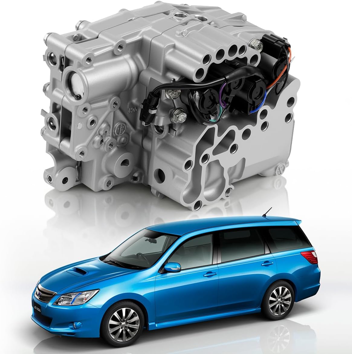
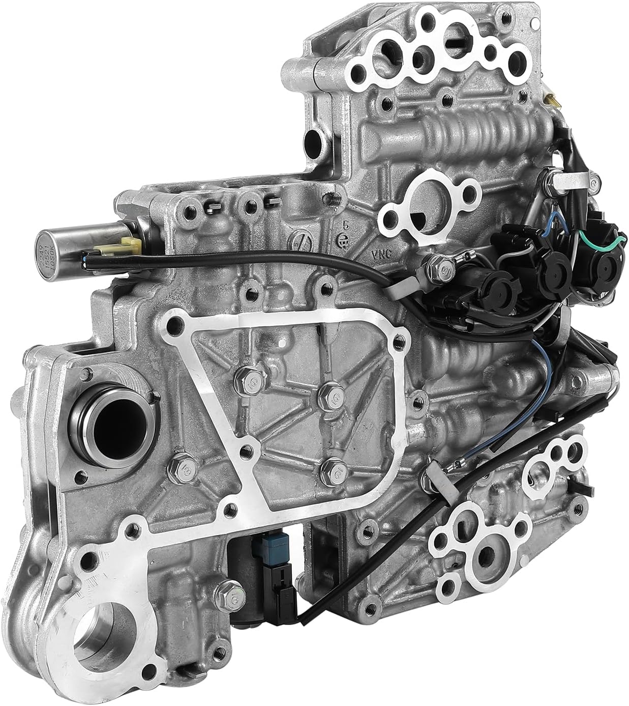
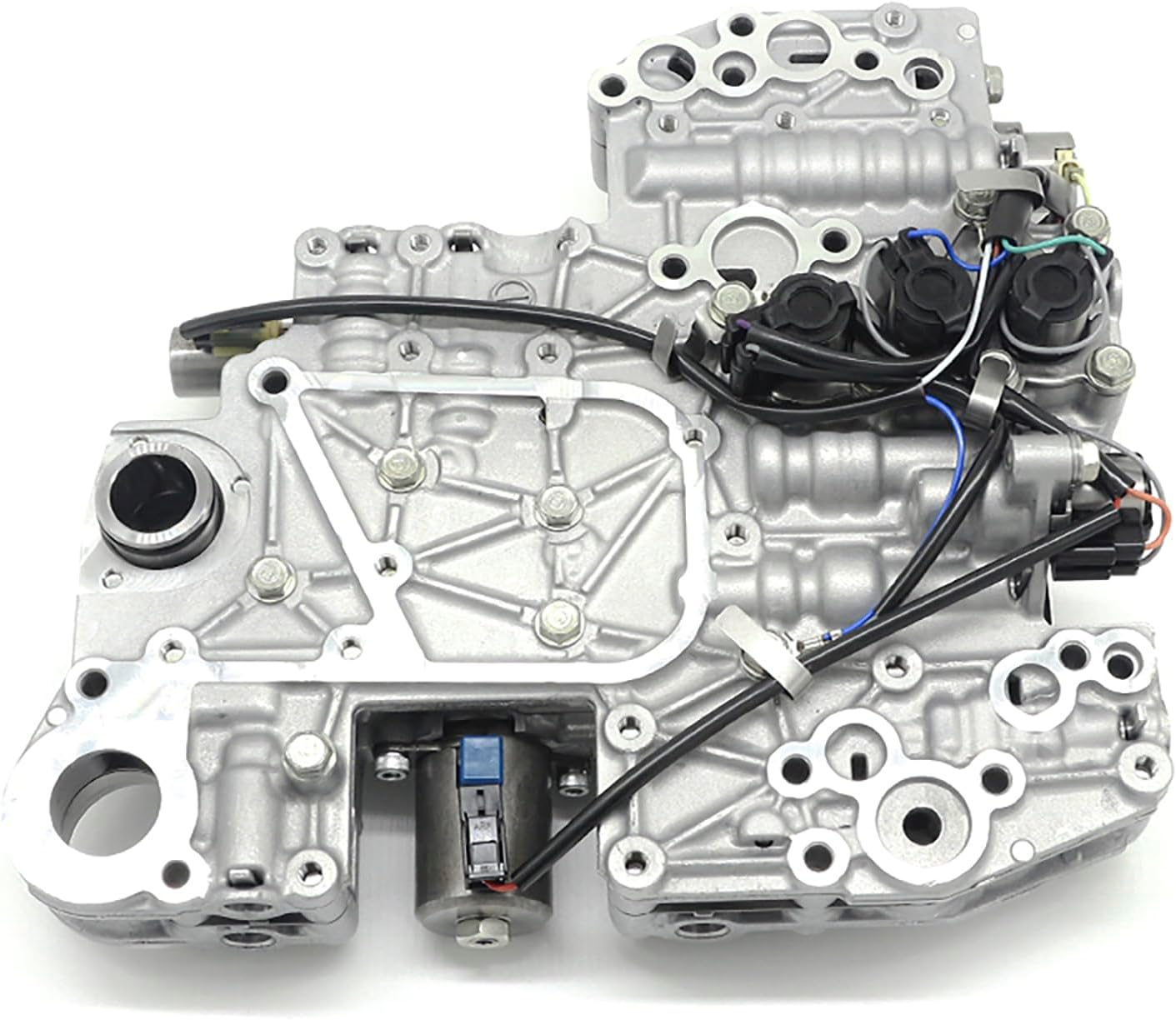
The TCM controls line and secondary pressure by pulse-width-modulating solenoids, so a low reading is not automatically a bad solenoid. Sonnax's JF011E valve body layout lists which bores go bad and what each one does to the car, and it reads like a limp-mode symptom list: a worn pump flow control valve causes push belt slippage, delayed engagement and low pump volume; a worn secondary pressure regulator valve bore produces push belt slippage, pulley fracture, chatter on acceleration and RPM surge; a worn primary pressure regulator valve bore causes chatter on acceleration, slipping in Forward and Reverse, and damaged valve body castings. The flow control valve in particular leaks pump output back to the low-pressure side of the pump, so you lose volume before you lose pressure, and the fix is reaming the bore to restore circularity and fitting an oversized valve (Sonnax 33510N-01) rather than swapping the valve body.
Branch 3: Ratio faults, and the most over-replaced part on a Jatco
The third branch is the module watching commanded ratio versus actual ratio. Jatco units position the primary pulley with a stepper motor that drives a ratio control valve in the valve body, feeding, holding or venting pressure to the primary pulley circuit. Two codes come out of that system and they are not the same problem:
- P1777 is a circuit code. Wiring, connector, or winding resistance. This one earns a resistance test.
- P1778 is a ratio code: a large difference between the commanded step count and the actual gear ratio. The stepper motor itself is rarely at fault.
Gears has been blunt about this for years: the stepper motor is one of the most over-replaced parts in these transmissions. For P1777, an ohmmeter at the stepper connector settles it. Across the two windings you should read 15 ohms between pins 1 and 2, 15 ohms between 2 and 3, and 30 ohms between 1 and 3, then the same pattern on the second winding: 15 ohms between 4 and 5, 15 between 5 and 6, and 30 between 4 and 6. Two 15-ohm halves in series reading 30 across the ends is a healthy winding. Anything else is the motor or its harness.
For P1778, put the meter away. Verify the primary and secondary speed sensor signals first, and if there is a speed sensor code, fix that before anything else, because the TCM calculates ratio from those two sensors. If the sensors are clean, the cause is internal: flow control valve wear, pulley leaks, or a worn or sticky valve body. That is the same short list from Branch 2, arriving by a different road.
The single most useful graph on a Jatco is the stepper motor position PID (counts or steps) next to the gear ratio PID. They should be mirror images of each other. If the step count is sweeping and the ratio is not following, the mechanical side is not obeying the command, and low pressure is the usual reason. That one screen separates "the module is confused" from "the hydraulics quit," which is the whole diagnosis.
The judder codes that get mistaken for limp
Customers describe CVT judder as the car "going into limp," and on a V6 Nissan there is a specific bulletin path for it. Per Nissan bulletin NTB17-039P (revised May 2023), covering 2013-2018 Altima, 2016-2022 Maxima, 2015-2022 Murano, 2013-2020 Pathfinder and 2015-2017 Quest with the V6 and CVT, the two codes split the repair:
- P17F0, CVT_JUDDER (T/M INSPECTION): the flow chart sends you into the transmission itself, removing the control valve and inspecting further.
- P17F1, CVT_JUDDER (C/U INSPECTION): remove the control valve, perform the CVT chain inspection, and if the chain checks out OK, install a new valve body only. If it does not, the sub-assembly is replaced first.
Two qualifiers in that bulletin save wasted labor. If the customer is not actually reporting judder, or if any DTC other than P17F0 or P17F1 is stored, the bulletin does not apply and you diagnose the other code first. Nissan also points to NTB15-014, enhanced diagnostic logic for CVT judder, which is a reprogram that may apply before you open anything.
It is not only Nissan: the Subaru valve body case
Chain-drive Subaru units land in the same place from a different direction. Subaru bulletin 16-156-25 (September 30, 2025) announces a CVT control valve body design change with an enhanced valve sleeve, covering 2012-2023 Impreza and Crosstrek, 2014-2023 Forester 2.5 and 2013-2019 Legacy and Outback 2.5L. The symptoms it addresses are DTC P2757 (torque converter clutch pressure control solenoid performance / stuck off) and P2762 (lock-up duty solenoid malfunction), plus shudder while accelerating from a stop and shudder while decelerating to a stop. The updated control valve kit is 31825AA055 for TR580-equipped vehicles.
The lesson generalizes: on both brands, the durable fix for a pressure-control complaint was a valve bore, not an electrical part. If your diagnosis keeps landing on a solenoid that tests fine electrically, you are looking at the bore it lives in.
NS-2 and NS-3 fluid, Subaru CVTF-II, Honda HCF-2, JF011E and JF015E filter and pan gasket kits, master rebuild kits, fill adapter tooling and fluid analyzers — shipped from the USA.
Shop CVT parts →The order of operations that works
- Pull every module, and record freeze frame before clearing. On a CVT, a stored code from another system can be the whole reason the bulletin path does not apply.
- Sample the fluid. Green or greenish-brown is correct on a Nissan. Red means the wrong fluid went in, and that alone explains premature fail-safe.
- Bring it to temperature and check level properly. 70 to 80 degrees C, CVTF count 158 to 161, engine idling, selector cycled. Not cold, not guessed.
- Refractometer the coolant. Over 60 percent glycol and the CVT cannot dump heat, no matter what you do to it.
- Graph stepper position against gear ratio. Mirror images means the hydraulics are following commands. Divergence means they are not.
- Watch secondary pressure voltage under load. Under 3 volts when it should be over means clamping force is short, and the power reduction you are chasing is the module protecting the belt.
- Ohm the stepper only for P1777. 15, 15, 30 across each winding. For P1778, go looking at the flow control valve and pulley leaks instead.
- Drop the pan and read the debris last, before you order. Fine metallic sludge on a CVT is pulley and chain material, and that changes the job from valve body to unit.
Keeping a CVT out of fail-safe
Almost every premature CVT fail-safe I see traces back to heat or fluid, and both are preventable. Use the specified fluid, not a universal that claims coverage. Set the level at temperature with a scan tool. Keep the cooling system at a 50/50 mix so the CVT cooler circuit can actually work. On any unit that has been apart or has a history of heat, the flow control valve bore deserves a vacuum test before the valve body goes back on, because that bore is where the pressure quietly leaks away long before a code sets.
And tell the customer the truth about towing and long grades. A CVT in fluid temperature protection is not broken. It is doing the one thing that keeps the belt off the pulley faces.
Related reading: our CVT failure patterns across brands, JATCO CVT Nissan problems and fixes, Subaru Lineartronic service guide, and reading transmission live data.
Sources
- Nissan Service Bulletin NTB12-057c / AT12-005c, "Altima, Sentra, and Rogue; CVT Fail-Safe Condition Service Information," September 9, 2016, via NHTSA. Backs the definition of fail-safe mode as fluid temperature protection logic and the "low power / reduced engine performance" complaint; the applied vehicle list; the three premature triggers (overfilled fluid, incorrect fluid type, incorrect coolant mix); the NS-2 / NS-3 fluid requirement and the green versus red fluid sample test with the drain-and-refill-twice remedy; the fluid level procedure at 70 to 80 degrees C with a CVTF count of 158 to 161; and the 60 percent ethylene glycol threshold with the refractometer requirement. static.nhtsa.gov
- Nissan Service Bulletin NTB17-039P / AT16-020P, "CVT Judder and DTC P17F0 or P17F1 Stored," May 9, 2023, via NHTSA. Backs the applied vehicles (2013-2018 Altima, 2016-2022 Maxima, 2015-2022 Murano, 2013-2020 Pathfinder, 2015-2017 Quest, V6 with CVT only); the code definitions P17F0 (T/M INSPECTION) and P17F1 (C/U INSPECTION); the repair flow chart including chain inspection and valve-body-only replacement when the chain checks out OK; the "does not apply if any other DTC is stored" qualifier; and the reference to NTB15-014 enhanced diagnostic logic. static.nhtsa.gov
- Subaru Service Bulletin 16-156-25, "CVT Control Valve Body Design Change / P2757, P2762, & P06EF," September 30, 2025, via NHTSA. Backs the enhanced valve sleeve design change, the applicability (2012-2023 Impreza and Crosstrek, 2014-2023 Forester 2.5, 2013-2019 Legacy and Outback 2.5L), the symptom list including shudder from a stop and shudder decelerating to a stop, and control valve kit part number 31825AA055 for TR580-equipped vehicles. static.nhtsa.gov
- Gears Magazine (ATRA) — "Jatco CVT Pressures Diagnostics." Backs the full pressure table: line pressure from about 140 psi at idle to approaching 900 psi; primary pressure from about 120 psi to over 700 psi; secondary pressure from about 60 psi to almost 900 psi; the secondary transducer reading about 0.7 V at idle and needing to exceed 3 V, which equals at least 550 psi; the PWM solenoid control of line and secondary pressure; and the rule that stepper motor position and gear ratio PIDs should be mirror images of each other. gearsmagazine.com
- Gears Magazine (ATRA) — "Stop Wasting Money on Jatco CVT Stepper Motors." Backs the P1777 versus P1778 distinction, the stepper motor resistance specification (15 ohms pins 1-2, 15 ohms pins 2-3, 30 ohms pins 1-3, and the same across pins 4-5, 5-6 and 4-6), the instruction to verify primary and secondary speed sensor signals before condemning anything, and the three real root causes of P1778: flow control valve wear, pulley leaks, and a worn or sticky valve body. gearsmagazine.com
- Sonnax — "Jatco/Nissan JF011E (RE0F10A) Valve Body Layout" and the Oversized Pump Flow Control Valve (33510N-01) product data. Backs the valve-by-valve symptom mapping used above: pump flow control valve wear causing push belt slippage, delayed engagement and low pump volume; secondary pressure regulator valve wear causing push belt slippage, pulley fracture, chatter on acceleration and RPM surge; primary pressure regulator valve wear causing chatter, Forward and Reverse slip and casting damage; and the repair method of reaming the bore to restore circularity and fitting an oversized valve rather than replacing the valve body. sonnax.com