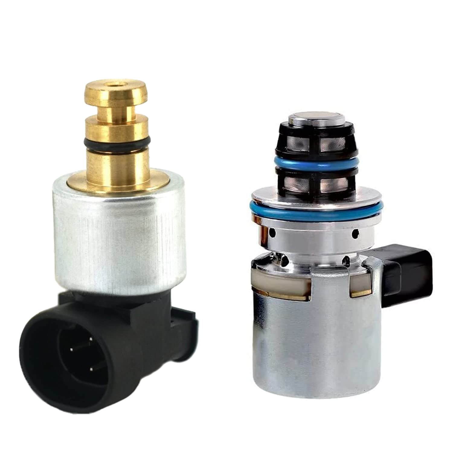
Search for 46RE speed sensor parts and you will find "input and output speed sensor" kits everywhere. Save the money on half of it. A 46RE has one transmission speed sensor: the output shaft speed sensor. Chrysler's 2001 Ram service manual (46RE chapter, page 21-597) puts it in the overdrive gear case, positioned over the park gear, where the park gear lugs trigger it as the output shaft turns. There is no input or turbine speed sensor in this transmission. Those live on the 45RFE and 545RFE.
What the truck does have is a second speed signal that people mistake for a transmission sensor: the vehicle speed signal that drives the speedometer. The PCM uses both, and it sets a different code for each. Knowing which is which is most of this diagnosis. This guide covers the 46RE in 1996-up Ram 1500 and gas 2500 trucks, the Durango and the Dakota. Factory numbers come from the 2001 Ram (BR/BE) service manual and Dave Skora's two-part 42-48RE series in ATRA's GEARS magazine. Sources are listed at the end.


What the 46RE Speed Sensor Actually Does
The 46RE shifts first through third with hydraulics, the old TorqueFlite way. Governor pressure pushes the 1-2 and 2-3 shift valves over against throttle pressure. What changed in 1996 is that there is no mechanical governor on the output shaft anymore. The PCM makes governor pressure with a duty-cycled solenoid, and it decides how much pressure to make from output shaft speed.
The 46RE Electronic Governor section of the manual (page 21-540) lists the pieces: governor body, transfer plate, governor pressure solenoid, governor pressure sensor, fluid temperature thermistor, throttle position sensor, transmission speed sensor and the PCM. The speed sensor is on that list for a reason. GEARS (July 2006) puts it plainly: if the computer does not receive an output speed sensor signal, it will not open the governor solenoid, and governor pressure stays at zero psi.
Here is how a healthy system behaves, per GEARS and the factory pressure test:
- Governor pressure is about zero at a stop and rises roughly 1 psi per mph. At 25 mph the PCM targets about 25 psi, reads the transducer and trims the solenoid duty cycle until it gets there.
- Around 40 mph the PCM shuts the governor solenoid off, which sends full line pressure into the governor circuit and holds the shift valves up. The 1-2 and 2-3 shifts are done by then.
- The 3-4 shift and converter lockup are handled by the overdrive and TCC solenoids, which the PCM also schedules from speed.
- The PCM uses output speed for housekeeping too. It recalibrates the governor pressure sensor's zero point every time output shaft speed drops below 200 rpm, and repeats that every 3 seconds while the truck sits still (manual page 21-541).
That last point matters for diagnosis. A speed sensor that reports speed while the truck is parked also interferes with that calibration, so the governor numbers on the scan tool stop making sense.
The Two Speed Signals, and the Code Each One Sets
The 46RE PCM watches two speed inputs, and the manual shows it cross-checking them. In the Electronic Governor section (page 21-542), on 4x4 trucks the PCM compares the electronic vehicle speed signal used by the speedometer to the transmission output shaft speed signal to decide when the transfer case is in low range. In low range it switches to a higher governor curve so the truck upshifts sooner instead of flaring the engine.
The emissions DTC chart in the same manual gives each signal its own code:
- P0720, Low Output Speed Sensor RPM. Chrysler's description: the relationship between the output shaft speed sensor and vehicle speed is not within acceptable limits. Output shaft speed is less than 60 rpm with vehicle speed above 15 mph (4-speed automatic only). Translation: the speedometer signal says the truck is moving, the transmission sensor says it is not.
- P0500, No Vehicle Speed Sensor Signal. No vehicle speed signal detected during road load conditions. This one points at the speedometer-side signal, not the transmission sensor.
So read the code before you buy a part. P0720 sends you to the sensor in the overdrive gear case, its connector and its two wires. P0500 sends you to the vehicle speed signal circuit. A truck with a dead speedometer and a P0500 but normal shifts probably does not need a transmission sensor at all.
One practical note from the bench. Because the PCM compares the two signals, anything that makes them disagree deserves a look when a 4x4 truck shifts oddly: a changed tire size or axle ratio without recalibrating the speedometer, or a speedometer signal that drops out intermittently. The fix there is calibration or the vehicle speed circuit, not a new output sensor.
46RE Output Speed Sensor Symptoms
- Stays in first and will not upshift. The classic. No output signal, no governor pressure, no 1-2 shift. The engine revs out in first until the driver lifts.
- Late, erratic 1-2 and 2-3 shifts. A weak or dropping signal makes the PCM think the truck is slower than it is, so governor pressure lags road speed and the shifts come late, then normal, then late again.
- Problems that start only when hot or only at speed. A sensor with a breaking winding, a loose connector, or metal fuzz stuck to the magnetic tip often reads fine in the driveway and drops out at 30 mph.
- Converter clutch or overdrive that will not engage, or hunts. Both are scheduled from speed.
- Harsh engagement, a second-gear start or no downshift at a stop. This is the opposite failure: a speed signal where there should be none. GEARS (October 2006) warns that the OSS should read 0 mph when the truck is stopped, and that any AC signal or electrical interference bleeding into the circuit will be read as road speed. The PCM then commands governor pressure the truck should not have at a standstill.
- P0720 with the check engine light on.
What a bad speed sensor usually does not do is start the truck in third. GEARS explains that when the computer sets one of the governor or 4th-gear codes it goes into failsafe, shuts the governor solenoid off, and governor pressure goes to maximum. The truck starts and runs in third. Third-gear start means failsafe: read codes and check the transmission relay feed. First-gear hold means zero governor pressure: check the speed signal. Our 46RE limp mode guide covers the third-gear side.
How to Diagnose a 46RE Speed Sensor Problem
Step 1: Codes and speed PIDs
Pull codes first. Then drive with a scan tool and watch transmission output speed next to vehicle speed. At a steady speed both should be smooth and should track each other. An output speed that drops to zero, spikes, or reads something at a stop is your answer. A vehicle speed that drops out while output speed stays steady points at the speedometer-side signal instead.
Step 2: Governor desired, actual and a gauge
This is the check that stops the parts cannon. The 42RE-48RE family is one of the few where the scan tool shows real measured pressure, because the governor transducer reports it to the PCM. Sonnax makes that point in its pressure gauge diagnostics article, along with the warning not to assume the pressure in the transmission matches what the scanner shows. So put a 0-100 psi gauge on the governor pressure tap and compare three numbers: governor desired, governor actual, and the gauge.
- Desired is zero or very low while driving: GEARS says the computer is not trying to make governor pressure because it may not realize the truck is moving. Check the output speed signal and the wiring from the sensor to the computer. If a good signal reaches the computer and it still does not recognize it, suspect the computer.
- Desired is right but actual and gauge are low: the speed sensor is doing its job. Move on to the governor solenoid, a blocked feed, or the relay supply. See our 46RE governor pressure solenoid guide.
- All three match and follow road speed, and it still shifts wrong: the electronics are fine. Look at the valve body and clutches.
For the gauge numbers, use Test Five in the 46RE hydraulic pressure test (manual page 21-489): gauge C-3292 on the governor port, selector in D, engine at curb idle with the brakes firmly applied. Governor pressure should be no more than 3 psi with the wheels stopped. Release the brakes and slowly raise speed, not over 30 mph. Pressure should rise smoothly about 1 psi per mph and drop back to 3 psi or less when you stop again. More than 3 psi at a stop is exactly what a noisy speed signal can cause, so if you see it, check the output speed PID at a standstill before blaming the solenoid.
Step 3: Check the signal itself
GEARS describes the output speed sensor as an AC-generating sensor: a toothed wheel passes the tip and the sensor makes its own voltage. It has two wires and no reference voltage. Put a meter on AC volts across the two leads, or better, a scope, and spin the output. GEARS' October 2006 pinout for a gas RWD truck lists the OSS signal at PCM pin B28 (light green/black) at about 3.0 volts AC at 30 mph, with the OSS ground on pin B25 (dark blue/black). Measure at the sensor and again at the PCM connector. If the sensor makes a clean signal and the PCM end does not see it, the problem is the harness.
On the scope, a good sensor shows an even wave that grows in amplitude and frequency with speed. Dropouts, flat spots or a ragged wave point to a failing coil, a damaged tip, or debris on the magnet. Signal at a standstill with the output not turning is interference. Look for the harness routed against ignition or alternator wiring, broken insulation, or a sensor connector that has been pried apart and let water in.
Replacing the Output Speed Sensor
The sensor is on the overdrive gear case at the rear of the transmission, with a two-pin connector. Figure 231 in the manual shows it as the sensor plus a seal, so the seal gets replaced every time. The job is short:
- Raise and support the truck. Unplug the connector and look at the pins for corrosion or spread terminals before anything else.
- Remove the sensor. Expect a small amount of fluid.
- Look at the sensor tip. If it is coated with metal fuzz, that debris came from inside the transmission. Pull the pan and look before you call it fixed.
- Install the new sensor with a new seal, reconnect it, and top up with Mopar ATF+4 as needed, checking the level hot.
- Clear codes, then road test with the scan tool connected. Confirm output speed reads 0 at a stop and tracks vehicle speed on the road, and that governor desired and actual follow each other.
If the tip was clean, the signal checks good, and the problem is still there, the sensor was never the cause. Go back to Step 2 and follow the governor numbers. A governor solenoid packed with debris, a transducer that reads wrong, or worn governor plug bores in the valve body all cause the same late or missing shifts. Our 46RE valve body testing guide covers the last one.
RE-Family Output Speed Sensor, OEM 4800879BB
The two-wire output shaft speed sensor from this guide. CoreTransmissionParts lists it for the 48RE, and the 4800879 part number is shared across the RE family, so compare it to the number and connector on your old sensor before ordering.
View the output speed sensor →Shop RE-family sensor and governor parts →
Frequently Asked Questions
Does the 46RE have an input speed sensor?
No. The 46RE has one transmission speed sensor, the output shaft speed sensor in the overdrive gear case over the park gear. The PCM gets engine speed from the crankshaft position sensor and a separate vehicle speed signal for the speedometer. Sensor pairs sold as 46RE input and output sensors are aimed at the 45RFE and 545RFE, which do have an input speed sensor.
What does P0720 mean on a 46RE?
On the 2001 Ram, Chrysler defines P0720 as a bad relationship between the output shaft speed sensor and vehicle speed: output shaft speed below 60 rpm while vehicle speed is above 15 mph. It means the PCM sees the truck moving on the vehicle speed signal but the transmission sensor says the output shaft is barely turning.
Can a bad output speed sensor keep a 46RE in first gear?
Yes. The 46RE shifts first through third with governor pressure, and the PCM builds governor pressure from the output speed signal. According to GEARS, with no output speed signal the computer will not open the governor solenoid, governor pressure stays at zero and the truck stays in first.
Why does my 46RE start in third gear?
A third-gear start is failsafe. When the PCM sets a governor or 4th-gear code, it shuts the governor solenoid off, which sends line pressure to the governor circuit and pushes the shift valves to third. Check codes and the transmission relay circuit before replacing the speed sensor, because a dead sensor usually causes a first-gear hold, not a third-gear start.
Sources
- Chrysler — 2001 Dodge Ram Truck (BR/BE) Service Manual, Automatic Transmission - 46RE, Speed Sensor (page 21-597). Backs the sensor location in the overdrive gear case over the park gear, the park gear lugs as the trigger, the output shaft speed function, and the sensor-and-seal assembly (Fig. 231). The same speed sensor description (located in the overdrive gear case, positioned over the park gear, triggered by the park gear lugs, signal sent to the transmission control module) appears in the 46RE/47RE section of the Chrysler 1998 Dodge Ram Truck Service Manual, archived in full at archive.org — Chrysler 1998 Dodge Ram Truck Service Manual.
- Chrysler — 2001 Dodge Ram Truck Service Manual, 46RE Electronic Governor (pages 21-540 to 21-542). Backs the transmission speed sensor as a governor control input, the transducer recalibration below 200 rpm output speed every 3 seconds, and the low-range detection that compares the speedometer vehicle speed signal to output shaft speed. The ManualsLib scan previously cited for these pages no longer resolves; the same governor-input function and low-range detection logic are independently described in ATRA GEARS Magazine's two-part 42-48RE series (cited below).
- Chrysler — 2001 Dodge Ram Truck Service Manual, 46RE Test Five - Governor Pressure (page 21-489) and Emissions Control DTC chart. Backs the governor pressure test (3 psi maximum at a stop, about 1 psi per mph up to 30 mph), the P0720 definition (output shaft speed under 60 rpm with vehicle speed above 15 mph) and the P0500 definition (no vehicle speed signal during road load). The same Test Five procedure (gauge C-3292 on the governor port, no more than 20.6 kPa / 3 psi at curb idle with the wheels held, rising about 1 psi per mph up to 30 mph) and the same P0720 (output shaft speed less than 60 rpm with vehicle speed above 15 mph) and P0500 definitions appear in the Chrysler 1998 Dodge Ram Truck Service Manual, Group 21 Test Five and the emissions DTC chart, archived in full at archive.org — Chrysler 1998 Dodge Ram Truck Service Manual.
- ATRA GEARS Magazine — Dave Skora, "Getting to Know the 42-48RE Series Transmissions, Part 1" (July 2006). Backs the hydraulic first-three-gears design, no OSS signal keeping the governor solenoid closed and governor pressure at zero, the roughly 1 psi per mph rule, the 40 mph solenoid-off handoff, the AC-generating two-wire sensor, and failsafe causing a third-gear start. gearsmagazine.com (PDF)
- ATRA GEARS Magazine — Dave Skora, "Getting to Know the 42-48RE Series Transmissions, Part 2" (October 2006). Backs the desired-versus-actual diagnostic path (no desired pressure means check the OSS signal and wiring, then the computer), OSS reading 0 mph at a stop, interference being read as road speed, and the gas RWD PCM pinout (OSS signal pin B28 at about 3.0 V AC at 30 mph, OSS ground pin B25). gearsmagazine.com (PDF)
- Sonnax — Transmission Diagnostics Using Pressure Gauges. Backs the point that the 42RE-48RE series reports actual governor pressure through a transducer while most units only show a command, and that a gauge is still needed to confirm what the scanner shows. sonnax.com
Shop 46RE governor solenoids and sensors, solenoid kits, valve bodies and rebuild kits, shipped fast from the USA.
Shop 46RE parts →