Nobody ruins a 4L60E with a cheap socket set. They ruin it by guessing at a number GM published a specification for. The unit comes apart with ordinary hand tools and goes back together with them too — right up until you hit one of the half-dozen places where the build lives or dies on a measurement. That is where the special tools live, and they are the only ones worth arguing about.
So this is not a list of everything with "4L60E" printed on the box. It is the short list, organized by what each tool lets you measure or protect, with the GM J-numbers so you know what you are actually buying.
The short version: five jobs on a 4L60E require a tool you cannot improvise — total end play (0.005–0.036 in), 2-4 band apply pin length (J 33037, checked at 98 lb in), clutch spring compression on the input and reverse input drums, Teflon seal installation and sizing on the turbine and stator shafts, and an inch-pound torque wrench for the valve body. Everything else on the list either saves you time or saves you a part. Those five save you the rebuild.
1. The end play setup: a dial indicator and the right adapter
Total end play is the most-skipped measurement on this unit and the one that quietly eats gear trains. The 4L60/E family has one setting, not two. There is a center support — the low/reverse one-way clutch outer housing, snap-ringed into the case — but the one-way clutch inner race floats up and down with gear set movement, so it does not divide the stack into a front and rear play the way a TH400 center support does. You measure the whole assembly, front to back, as one.
The GM overhaul procedure calls for a stack of four tools: J 24773-A (oil pump remover and end play checking fixture), J 8001 (dial indicator set), J 25025-7A (dial indicator mounting post, or an 11-inch bolt and a lock nut), plus the correct end play fixture adapter for your turbine shaft — J 25022-A for the 245 mm shaft, J 34725 for the 298 mm shaft. Zero the indicator, pull up on the fixture, read it.
Specification: 0.13–0.92 mm, or 0.005–0.036 in. Sonnax TASC Force specialist Randall Schroeder, writing in Transmission Digest, prefers to land in the 0.020–0.025 in window rather than anywhere in the range, and that is good advice. The adjustment is the selective washer between the input housing and the thrust bearing on the oil pump hub. If the indicator shows no play at all, that washer and bearing were probably stacked wrong, not sized wrong.
Two details that will save you a teardown. The pump gasket changes the reading: with a new gasket subtract 0.005 in, with no gasket add 0.005 in. And if the factory shim you need is not on the shelf, shim stock can be stacked — under the factory shim in the input drum in roughly 0.015 in increments, or under the rear-hub-to-case bearing at the bottom of the case in roughly 0.010 in increments.
The bench check that costs nothing
Before any of that, do the gear set check on the bench. Stack the planetary components and bearings onto the output shaft in order, install the snap ring inside the front planet to hold it together, stand the assembly sun-shell-face-down, and check play between the output shaft and rear hub with a dial indicator or feeler gauge. Sonnax specialist Steve Garrett puts the target around 0.020–0.030 in; Schroeder's rule is no more than 0.030 in of movement. Outside that, something in the stack is mismatched.
This matters more than it used to. GM revised the reaction carrier bearing to a thicker design in March 2007 and changed the reaction carrier and shaft to suit, across both the four-pinion and five-pinion carriers. Match all three as a set and nothing happens. Mix old and new and you get an end play you cannot correct and an output shaft snap ring that will not seat.
2. The 2-4 band apply pin gage (J 33037)
The 2-4 band apply pin sets how much travel the servo has before the band takes hold. Too short and the band slips in 2nd and 4th; too long and it drags. There is no eyeball version of this check.
The GM procedure is specific: disassemble the 2-4 servo, install the band apply pin and J 33037, secure the tool with the servo cover retaining ring, then apply 11 N·m (98 lb in) of torque. If the white line shows in the gage slot, the pin length is right; if not, select a different pin. That 98 lb in is not a suggestion — the gage is calibrated to that load, so this is a torque-wrench check, not a feel check.
Getting the servo out wants J 29714-A (servo cover compressor), so the cover comes off under control instead of launching the retaining ring across the shop, and J 22269-01 (accumulator and servo piston remover) to compress the second apply piston assembly.
While you are in there: running an aftermarket servo kit, set servo travel between 0.075 in and 0.125 in with a dial indicator, per the Sonnax instructions those kits ship with. Never shim a servo to correct band adjustment — that pushes the piston deeper into the bore where it is more likely to bottom out and take the band with it. Never fit a wider band to a used drum either; the old band dishes the drum surface, and a wide band on a dished drum slips in 2nd, then glazes and burns.
3. An inch-pound torque wrench, and the sequence that goes with it
A 4L60E has a wide torque spread, and the low end is where people get lazy. Keep both a ft-lb and an in-lb wrench on the bench.
| Fastener | Torque |
|---|---|
| Pump cover bolts | 24 N·m (18 lb ft) |
| Pump-to-case bolts | 24 N·m (18 lb ft) |
| Valve body and TCC solenoid bolts | 11 N·m (8 lb ft), spiral sequence |
| 1-2 accumulator housing bolts | 11 N·m (8 lb ft) |
| Transmission oil pan screws | 12 N·m (9 lb ft) |
| Parking lock bracket bolt | 31 N·m (23 lb ft) |
| Cooler line connectors | 38 N·m (28 lb ft) |
The one to read twice is the valve body. The GM procedure carries an explicit warning that certain valve body bolts must be tightened in a spiral pattern, and that tightening them at random may distort the valve bores and inhibit valve operation. That is a perfectly good valve body ruined at the last step by an impact driver and a bad habit. Torque wrench, spiral out from the center, 8 lb ft.
The pump also needs J 21368, the pump body and cover alignment band, installed before you torque the pump cover bolts. Torque a pump cover without banding the halves together and you can pinch the rotor and kill the pump on startup.
4. Spring compressors, seal protectors and drivers
These are the tools that stop you from destroying a part you just paid for.
- J 23327-1 clutch spring compressor with the J 25018-A adapter — gets the retaining rings out of the input, reverse input and forward clutch assemblies. A shop press and a socket is how drums get gouged.
- J 36418-1B turbine shaft seal installer and J 36418-2A sizer — the four Teflon oil seal rings go on with the installer, then the sizer stays on the shaft until the reverse input clutch is installed. Skip the sizer and the rings will not clear the bore.
- J 29882 (overrun clutch seal protector) and J 29883 (forward clutch seal protector) — cheap plastic, saves lip seals.
- J 34196-B and J 21465-01 bushing service sets, plus J 41778-1 and J 41778-2 for the pump body bushing and its position stop. Bushings driven crooked or too deep are a recurring cause of low line pressure and a killed pump.
- J 8763-02 holding fixture and base — every measurement above assumes the unit is sitting square.
- J 41510 Torx Plus bit for the converter housing bolts. Wrong bit, rounded head, bad day.
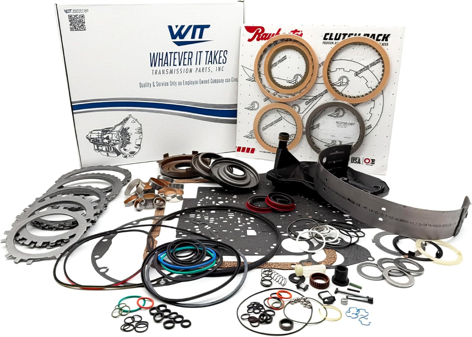
4L60E Rebuild Tool Kit, 7-Piece (1993-2008)
If you are building your first 4L60E rather than outfitting a shop, this is the sensible way in: seven of the purpose-built service tools this job needs in one box, built to OEM specification for 1993-2008 units, instead of chasing individual J-numbers at three times the money. Add the pump alignment band and the turbine and stator shaft Teflon seal installer separately if your kit does not cover them.
See the 4L60E 7-piece rebuild tool kit →5. Clutch travel: a feeler gauge and the numbers
Clutch pack clearance separates a rebuild that shifts crisply from one that burns a pack in 8,000 miles. A feeler gauge or dial indicator, plus the published travel ranges:
| Clutch pack | Plate travel |
|---|---|
| 3rd and 4th clutch | 0.90–2.10 mm (0.035–0.083 in) |
| Reverse input clutch | 1.02–1.94 mm (0.040–0.076 in) |
| Forward clutch, 245 mm converter units | 0.766–1.756 mm (0.030–0.069 in) |
| Forward clutch, 298/300 mm converter units | 0.866–1.876 mm (0.034–0.074 in) |
Forward clutch travel changes with converter size, one more reason to identify the unit before ordering a kit. Selective backing plates are how you land in range; the GM procedure has you seat the selective backing plate at roughly 89 N·m (20 lb ft) while making the check.
While the drums are apart, air check them. Apply air to the feed holes in the turbine shaft to verify the 3rd and 4th clutch, the forward clutch and the overrun clutch each stroke and seal. An air nozzle with a rubber tip and a 4L60E air test plate is a ten-dollar habit that catches a rolled lip seal before the unit is back in the truck.
6. Converter end play: J 35138 and a magnetic base
A converter that is out of end play will take your fresh pump with it, and you cannot tell by shaking it. The check needs J 35138 (converter end play checker), J 26900-13 (magnetic indicator base) and J 8001, with J 39195 used on the 300 mm converter.
| Converter | End play |
|---|---|
| 245 mm | 0–0.38 mm (0–0.015 in) |
| 298 mm | 0.1–0.48 mm (0.004–0.019 in) |
Two things from the GM inspection list worth repeating: do not condemn a converter for fluid odor or discoloration alone when no metal or clutch material is present, and do not bother trying to flush one — GM does not recommend it. Replace it for metal found after flushing the cooler and lines, a scored hub, external hub leakage, a broken or poorly fitting pilot, internal stator damage, coolant contamination, or excessive end play.
7. Valve body tools: vacuum testing, then reaming
This is where the tool budget gets real, and where you decide whether you are rebuilding valve bodies or sending them out. Both are defensible. Installing a used valve body you never tested is not.
Vacuum testing
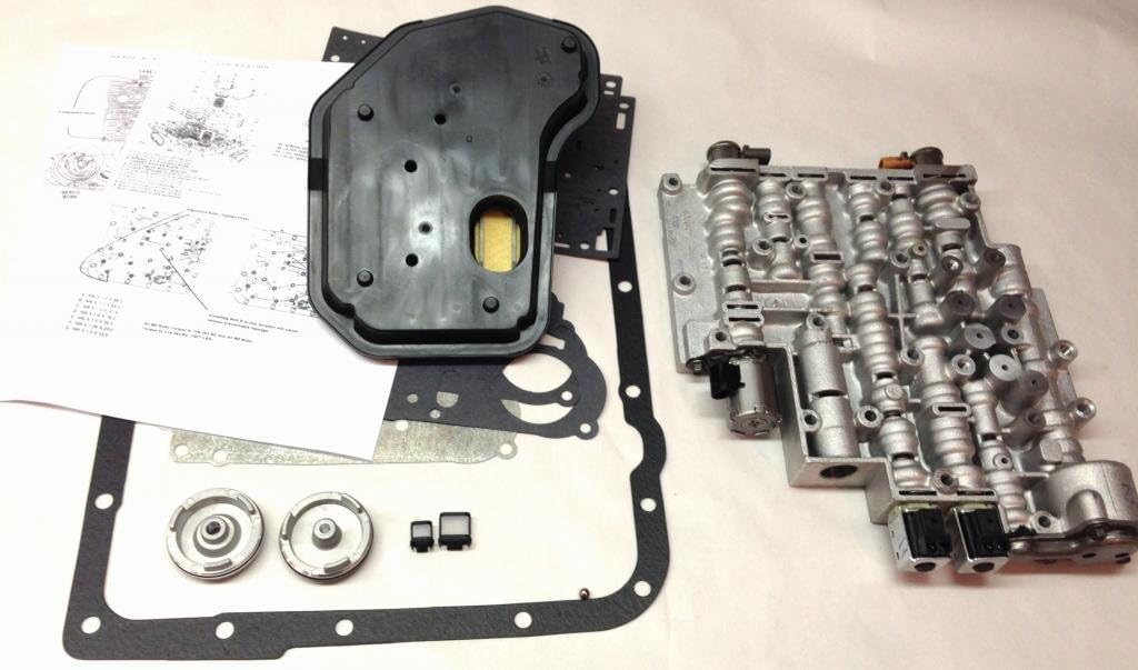
Vacuum testing gives you a repeatable number for bore wear instead of a shrug. Sonnax builds a plate for this unit — 77754-VTP, covering 4L60-E, 4L65-E and 4L70-E — that seals the whole casting at once so you test each location by moving the vacuum tip, driven by a stand such as VACTEST-01K.
Read the gauge like this, per Sonnax: 26 to 24 in-Hg is very good; 23 to 20 in-Hg is questionable and needs inspection; 19 in-Hg or less means excess clearance in that bore. The Sonnax 4L60-E vacuum test guide maps locations to symptoms — TCC regulator valve to codes P0894 and P1870, actuator feed limit valve to erratic line pressure and solenoid performance codes, 3-4 relay and 3-4 shift valves to a burnt 3-4 clutch and 2-4 band, reverse abuse valve to delayed reverse and low/reverse clutch distress.
One high-value test is not in the valve body at all: vacuum test the #7 checkball in the case servo area, the third accumulator checkball assembly. Even minor leakage there ties directly to band and 3-4 clutch failure.
Reaming
To ream bores rather than replace the casting, the entry fee is the VB-FIX reaming fixture plus the specific tool kit for the bore you are fixing. Sonnax kits whose part numbers begin with "F-" require VB-FIX; the others are standalone bench tools. For large pump bodies that will not sit on the standard base plate there is an oversized plate, VB-06.
The technique is not negotiable if you want the bore to come out round:
- Clean the bore in a solvent tank, then lubricate bore and reamer generously with cutting fluid — ideally a continuous flow of water-soluble fluid.
- Turn the reamer with a low-RPM, high-torque drill regulated to a maximum of 200 RPM.
- Use little or no inward force. Pushing produces poor surface finish and sporadic material removal.
- Never turn a reamer backward. It dulls prematurely, and a dull reamer cuts a smaller hole.
- Never turn one with a crescent wrench, ratchet or pliers. Use a loose-fitting reamer socket and a wobble adapter.
- Deburr the exit side of lands and bores, then get every trace of abrasive back out with solvent and a lint-free rag in progressive steps.
Budget for consumables: a Sonnax reamer averages 50 to 70 bores before resharpening or replacement, and resharpening is a job for a professional tool sharpener, not a bench grinder.
The tool you make yourself
Not everything needs a part number. The GM procedure for installing the third accumulator retainer and ball assembly has you take a 9.5 mm (0.375 in) diameter metal rod and scribe a mark at 42 mm (1.653 in) to control installation depth. Five minutes and a piece of drill rod. Between that and a good set of internal and external snap ring pliers, a magnet, a parts washer and a genuinely clean bench, you have covered most of what goes wrong.
What to buy first
If the budget only stretches so far, buy in this order: inch-pound torque wrench, dial indicator and end play fixture, J 33037 band apply pin gage, clutch spring compressor, seal installer and sizer set. Those five let you hit every published specification in the build. The vacuum setup and reaming fixture come later, and only if you do enough valve bodies to justify them — below roughly a unit a week, a tested reman valve body is the better math.
The pattern behind all of it: the 4L60E does not fail because someone lacked strength. It fails because someone lacked a number. Every tool above exists to hand you a number.
Shop 4L60E rebuild and overhaul kits, clutch packs, 2-4 bands and servos, bushing kits, filters and pan gaskets, plus the service tools to install them — shipped fast from the USA.
Shop 4L60E parts →Sources
- GM 4L60-E Overhaul Procedures (GM service procedure, reproduced as AUTO 211 course reference material) — source for the J-tool numbers used throughout, the transmission end play specification of 0.13–0.92 mm (0.005–0.036 in), the J 33037 band apply pin check at 11 N·m (98 lb in), fastener torques including 24 N·m (18 lb ft) pump bolts and 11 N·m (8 lb ft) valve body bolts, the spiral valve body tightening warning, the clutch plate travel ranges, the converter end play specifications and inspection criteria, and the 9.5 mm rod scribed at 42 mm for the third accumulator retainer. 4L60-E Overhaul Procedures (PDF)
- Transmission Digest — "All Work and No Play: Setting Endplay to Prevent 4L60/E Gear Train Failure," by Randall Schroeder, Sonnax TASC Force. Source for total versus front/rear end play on the 4L60/E, the 0.005–0.036 in range and the preferred 0.020–0.025 in window, the 0.005 in pump gasket correction, the 0.030 in gear set movement limit, and shim stock in 0.015 in and 0.010 in increments. transmissiondigest.com — Setting Endplay
- Transmission Digest — "Too Close For Comfort: Pinpointing 4L60E Gear Train Assembly Problems," by Steve Garrett, Sonnax TASC Force. Source for the 0.020–0.030 in bench end play target and the March 2007 GM reaction carrier bearing, carrier and shaft revision that must be matched as a set. transmissiondigest.com — Gear Train Assembly Problems
- Sonnax — "GM 4L60-E, 4L65-E, 4L70-E Vacuum Test Guide." Source for the valve body vacuum test locations and the wear symptoms tied to each valve: TCC regulator, actuator feed limit, 3-4 relay and 3-4 shift, reverse abuse, and accumulator valve. sonnax.com — 4L60-E Vacuum Test Guide
- Sonnax — "Reaming Instructions: If VB-FIX Required," plus the VB-FIX product data. Source for the 200 RPM maximum reamer speed, the cutting fluid requirement, the cautions against reversing or pushing the reamer, the 50–70 bore reamer service life, the "F-" tool kit convention, and the VB-06 oversized pump base plate. sonnax.com — Reaming Instructions
- Sonnax — "Building the Killer 4L60E: Top Tips for Optimizing Your Transmission Upgrades," plus Vacuum Test Plate Kit 77754-VTP product data. Source for the 0.075–0.125 in servo travel setting, the warnings against shimming a servo and against fitting a wide band to a used drum, the #7 third accumulator checkball leak test, and the 77754-VTP plate and VACTEST-01K test stand. sonnax.com — Building the Killer 4L60E
Vacuum reading thresholds of 26–24 in-Hg (very good), 23–20 in-Hg (questionable, inspect) and 19 in-Hg or less (excess clearance) are the published Sonnax interpretation guidance for 4L60-E valve body testing.