Nobody rebuilds a 4L60E because the detent spring went bad. You are in there for a burned 3-4 pack or a slipping band, and the manual valve linkage is just the stuff you take off to get to the good parts. That is exactly why it gets put back sloppy. A stretched detent spring, a bent manual valve link, or a hex nut that never saw a torque wrench will send a freshly built unit right back into your bay with a harsh shift complaint and a P1810 that has nothing to do with electronics. Here is the mechanical chain from the shift cable to the manual valve, what wears in it, and every GM torque spec for putting it back together.
The short version: The manual shaft turns the inside detent lever (the rooster comb). The rooster comb does two jobs at once — it pushes the park pawl actuator rod and it drags the manual valve through the manual valve link. The detent spring and its roller drop into the comb's notches to hold each range. If that roller does not seat crisply, the manual valve parks between positions, the TFP pressure switches read a combination that does not exist, and the PCM sets P1810 and defaults to D2 line pressure. GM torque: detent spring bolt 20-27 N·m (15-20 lb ft), manual shaft nut 31 N·m (23 lb ft), valve body bolts 11 N·m (8 lb ft) [5].
What the Manual Valve Actually Does
The manual valve is not a regulating valve. It does not modulate pressure, it does not respond to a solenoid, and it has no spring fighting it. It is a distributor: line pressure comes in, and depending on where the driver parked it, the valve routes that pressure to the circuits belonging to the selected range. As Sonnax TASC Force specialist Jim Dial puts it in Transmission Digest, the main function of a manual valve is to connect hydraulic pressure to the clutches or brakes tied to a Forward, Manual, Reverse or Park position, and a second, less obvious function is to provide an exhaust path — on most units the reverse circuits dump through the manual valve when it moves toward the Drive positions [1].
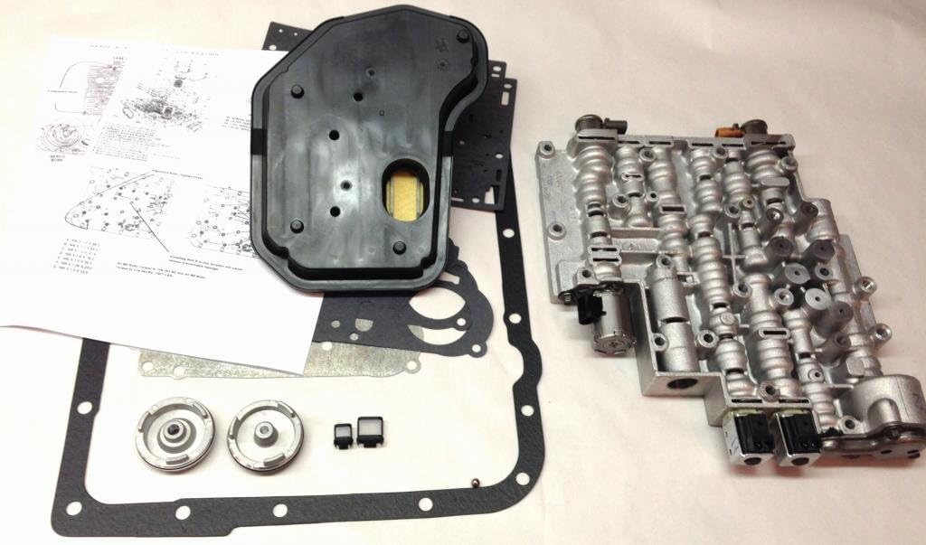
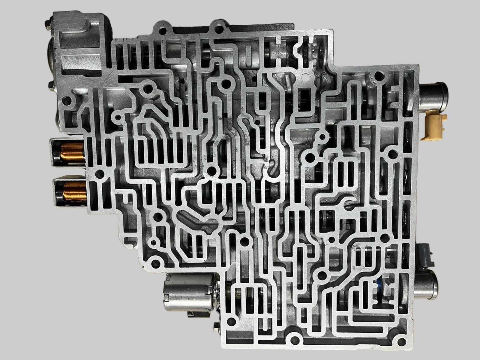
On the 4L60E, the manual valve lives at the outboard edge of the valve body and is item 201 in the Sonnax exploded view of the casting, right next to the 3-2 control valve [2]. It is the longest valve in the body and the only one with a link hooked to it.
Because it is a straight distributor with generous bore clearance, the manual valve does not vacuum test like the pressure regulator or the TCC regulator. Dial's guidance is worth memorizing: manual valves typically have more bore clearance and lower vacuum readings than regulating valves, so record what you get and compare against a known-good valve body rather than expecting a regulating-valve number [1]. Push the valve side to side while you test to feel for a bore that has gone oval.
The Mechanical Chain, Piece by Piece
Run your finger along it in order. The manual shaft (84) passes through the case and carries the manual shaft seal (82) and a retainer (83). Inside the case, the shaft is clamped into the inside detent lever (88) — the rooster comb — by a hex head nut (90). The comb carries the parking lock actuator assembly (85) on one arm and the manual valve link (89) on the other. Bolted to the valve body is the manual detent spring assembly (63) with a single bolt (64) [5].
GM's own patent on this actuator describes the geometry better than most service manuals do. The rooster comb rotates with the selector shaft and carries both a cam slot and a set of detent notches, and the patent states plainly that "the detent spring 18 and roller 22 are operable in combination with the detent notches 24 to maintain the rooster comb in a selected position" [4]. That is the whole job of the detent spring: hold the comb, and therefore the manual valve, at a discrete position instead of anywhere the cable happens to leave it.
The second half of that patent is the part rebuilders should care about. The drive pin that couples the comb to the range selector valve rests freely in an annular groove in the valve and is guided by slots in the valve body, so that "the side load effect from the cam slot 26 is absorbed by the valve body portion 34 and does not side load the valve 38" [4]. The design deliberately keeps the sideways force of the cam out of the manual valve bore. When the link is bent, mis-hooked, or the wrong length for the shaft you installed, you defeat that: the link pries on the valve instead of pulling it straight, and you get bore wear on the one valve that is supposed to never see side load.
Why a Worn Detent Sets P1810
This is the connection most people miss, and it is the reason detent service is worth doing properly.
Bolted to the 4L60E valve body is the transmission fluid pressure (TFP) manual valve position switch. Per GM service information, that unit is five pressure switches — two normally-closed and three normally-open — plus a transmission fluid temperature sensor combined into one assembly. The PCM feeds ignition voltage to three range signal circuits; the pressure switches ground one or more of them in various combinations, and the PCM compares the resulting voltage pattern against a stored TFP manual valve position switch logic table to decide which range you selected [3].
Notice what the switch is really sensing: valve body pressure, which is a direct consequence of where the manual valve is sitting. It is a mechanical position sensor that happens to work hydraulically. Two useful quirks fall out of that. First, the switch cannot distinguish Park from Neutral, because the monitored pressures are identical in both. Second, disconnecting the transmission's 20-way inline connector removes the ground path for all three range signals, and with the engine off and the key on the PCM will read D2 — a handy known-state check when you are chasing a wiring fault [3].
Now put a tired detent spring in the picture. The roller no longer drops firmly into each notch, the comb settles slightly off-center, and the manual valve stops short of fully uncovering or fully covering a port. The pressure switches see a combination that is not in the table. GM's set condition is an invalid TFP switch state held for 60 seconds. P1810 is a type B DTC, and the default actions are the ones that make the customer call you back: the PCM commands D2 line pressure, commands a D4 shift pattern, and freezes shift adapts [3]. Maximum line pressure with frozen adapts feels exactly like a bad rebuild.
You can confirm on the scan tool that the pressure default is actually active rather than guessing at it. ATRA's GEARS coverage of GM pressure control gives the numbers to compare against on a healthy 4L60E: at idle you should see roughly 10 percent engine load with 0.9 to 1.1 amps commanded to the pressure control solenoid, and during a wide-open-throttle pull just before the 1-2 shift engine load should climb to 90 to 100 percent while solenoid command drops to 0.2 amps or lower [7]. A unit sitting at or near the low-current, high-pressure end of that range at idle is being commanded to maximum line pressure. If that is what you find alongside P1810, the harshness the customer is complaining about is the default strategy, not a clutch or an accumulator, and the repair is the detent and switch work below rather than another teardown.
GM's diagnostic aid for P1810 also points at housekeeping: sediment in the valve body can cause improper TFP switch operation, and where sediment is suspected the instruction is to clean the valve body and replace the switch [3]. Inspect the switch for damage, debris, cracked connector, loose pins, and missing O-rings before it goes back on [5].
Teardown Order That Keeps the Check Balls Home
GM's sequence exists for a reason. Working from the pan up: remove the TFP switch bolts and lift the switch off, then the manual detent spring bolt (64) and the detent spring assembly (63), then all valve body bolts (62) and the fluid level indicator stop bracket (93). Lift the valve body carefully and level so the check balls stay on the spacer plate where they belong, and disconnect the manual valve link from the manual valve while you lift [5]. Trying to pull the valve body before the link is free is how links get bent.
For the internal linkage itself, the order is hex nut (90) and manual valve link (89), then inside detent lever (88) and the parking lock actuator assembly (85), then the manual shaft retainer (83) and manual shaft (84), and finally pry the manual shaft seal (82) out [5]. That seal is a common weep point on high-mileage units and is worth replacing every time the linkage comes apart.
What to inspect while it is on the bench
- Detent spring assembly (63) — cracks, damage, a flat-spotted or seized roller, and set. A spring that no longer snaps the roller into a notch is done.
- Inside detent lever (88) — cracks, and notches that have been rounded off by a worn roller. Rounded notches mean the comb can drift between ranges.
- Manual valve link (89) — any bend at all. It should be straight and its hooks should be round, not egg-shaped.
- Manual shaft (84) — burrs and damage; retainer (83) — cracks; hex nut (90) — stripped or stretched threads.
- Parking lock actuator assembly (85), parking brake pawl (81), and the parking pawl return spring (80) — damage, cracks, or a broken or missing return spring [5].
GM Torque Specifications for the Job
Every number below is from GM's Hydra-Matic 4L60-E overhaul procedures [5]. Use a torque wrench on all of them — the detent spring bolt in particular is one people run down with an impact, and stripping that hole means a case repair.
| Fastener | Torque |
|---|---|
| Manual detent spring bolt (64) | 20-27 N·m (15-20 lb ft) |
| Manual shaft to inside detent lever hex nut (90) | 31 N·m (23 lb ft) |
| Parking lock bracket bolt (87) | 31 N·m (23 lb ft) |
| Control valve body bolts (62) | 11 N·m (8 lb ft), in the specified sequence |
| 1-2 accumulator housing bolts (58, 59) | 11 N·m (8 lb ft) |
| Transmission oil pan screws | 12 N·m (9 lb ft) |
| Cooler line connectors | 38 N·m (28 lb ft) |
Two assembly details from the same procedure that save comebacks. GM calls for J-25025-5 guide pins to hang the valve body while you connect the manual valve link to the manual valve, then two bolts to hold it, then pull the pins [5]. Guide pins are not optional if you want the gaskets and spacer plate to stay aligned.
And the valve body does not use one bolt. GM lists seven sizes in the pattern — M6 x 1.0 in 65.0, 54.4, 47.5, 35.0, 18.0 and 12.0 mm lengths, plus one M8 x 1.25 x 20.0 [5]. A long bolt in a short hole bottoms out and cracks the casting; a short bolt in a long hole holds nothing. Use a bolt board, and finger-tighten everything before you torque in sequence.
Get the Right Parts for the Year
The linkage is not one part number across the family, and mixing generations is a real trap when you are building from a core pile. Industry parts catalogs break the 700-R4 / 4L60E linkage down by roller width and shaft length: the manual detent spring for 1982-2008 units uses a .375 in. wide roller, while the 2009-13 spring uses a .540 in. wide roller. Manual shafts run roughly 4-1/4 in. on 1982-up 700-R4 / 4L60E, 5 in. on 1996-2008 4L60E, and a 5 in. single-threaded-end shaft on 2009-13 units built for the internal mode switch. The 2009-13 4L60E/4L65E rooster comb integrates the internal mode switch with a six-prong connector, and its linkage assembly uses one set of threads where the 1996-2008 assembly uses two [6].
Match the roller width to the comb notches and the shaft length to the case. A wide-roller spring against a narrow-notch comb feels fine on the bench and wanders between ranges in the vehicle.
4L60E Shifter Selector Shaft Seal Remover & Installer Tool Set
The manual shaft seal is the one piece of this job you cannot do well with a screwdriver and a socket — pry it and you score the bore, drive it with the wrong tool and it goes in cocked and weeps. This is the purpose-built remover and installer for the 4L60E selector shaft seal. Or browse the full 4L60E parts collection at our sister store.
Shop the 4L60E selector shaft seal tool set →Verifying the Job Before It Leaves the Bay
Do not sign off on feel alone. Three checks, in this order.
- Detent feel by hand. With the shift cable disconnected at the transmission, rotate the manual lever through every position. Each notch should catch with an unmistakable click and hold against light pressure. Vague, mushy, or a comb that can be parked between two notches means the spring, the comb, or both are still wrong.
- Range agreement on the scan tool. Key on, engine off, watch the PCM's decoded transmission range parameter while someone moves the selector through P-R-N-D-3-2-1. Every position should agree with the shifter, and Park and Neutral will read the same by design — that is normal, not a fault [3]. Any position that reads a different range, or flickers, points back at manual valve travel.
- Start inhibit and park hold. The engine should crank only in Park and Neutral. On a slight grade, with the brake released, Park alone must hold the vehicle. If Park is lazy to engage or pops out, look at the parking lock actuator, its return spring, and the comb.
Ten minutes of linkage inspection on the bench is cheaper than pulling a transmission for a P1810 that was never electrical. If you are already in the valve body, our 4L60E valve body rebuild walkthrough and separator plate and check ball guide cover the rest, and shift solenoid diagnosis covers the electrical side that P1810 gets blamed for.
Shop 4L60E detent springs, rooster combs, manual shafts and seals, internal linkage assemblies, valve bodies and the tools to install them — shipped fast from the USA.
Shop 4L60E parts →Sources
- Transmission Digest — "Hydraulics Fundamentals: Manual Valves," Jim Dial, Sonnax technical specialist and TASC Force member, February 11, 2020. Backs the manual valve's role as a pressure distributor and reverse-circuit exhaust path, and the caution that manual valves have more bore clearance and lower vacuum readings than regulating valves. transmissiondigest.com/hydraulics-fundamentals-manual-valves/
- Sonnax — GM 4L60-E, 4L65-E, 4L70-E Vacuum Test Guide. Backs the manual valve's identification as valve body item 201 in the OE exploded view and the vacuum-test methodology for the casting. sonnax.com/tech_resources/441
- GM service information, DTC P1810 circuit description for 4L60-E / 4L65-E (2005 Chevrolet Silverado 1500 service manual). Backs the TFP manual valve position switch construction (five pressure switches, two normally-closed and three normally-open, plus TFT sensor), the three range signal circuits and stored logic table, the Park/Neutral indistinguishability, the 20-way connector D2 default, the 60-second invalid-state set condition, and the type B DTC default actions of D2 line pressure, D4 shift pattern and frozen adapts. The free online reproduction this post originally linked has gone offline; the P1810 chart is in GM Service Information, available by subscription through ACDelco TDS (acdelcotds.com).
- US Patent 5,934,436, "Actuator mechanism for a transmission parking pawl and selector valve," General Motors Corporation, issued August 10, 1999. Backs the rooster comb / detent notch geometry, the detent spring and roller holding the comb in a selected position, and the drive pin arrangement that keeps cam side load out of the selector valve. patents.google.com/patent/US5934436A/en
- GM Hydra-Matic 4L60-E overhaul procedures (GM service information, hosted PDF). Backs every torque specification in this article, the component call-out numbers, the teardown and reassembly sequence, the J-25025-5 guide pin requirement, the seven valve body bolt sizes, and the TFP switch inspection list. 4L60-E Overhaul Procedures (PDF)
- Whatever It Takes Transmission — 4L60E internal linkage parts catalog. Backs the.375 in. (1982-2008) versus.540 in. (2009-13) detent spring roller widths, the 4-1/4 in. / 5 in. manual shaft lengths, and the 2009-13 internal mode switch rooster comb and single-thread linkage assembly. wittrans.com — 4L60E linkage parts
- ATRA / GEARS Magazine — "Controlling Pressure: General Motors." Backs the scan-tool reference values used to confirm a commanded line-pressure default on a 4L60E: approximately 10% engine load with 0.9-1.1 amps commanded to the pressure control solenoid at idle, and 90-100% engine load with solenoid command falling to 0.2-0 amps during a wide-open-throttle pull just before the 1-2 shift; also backs the description of the computer raising and lowering line pressure through the electronic pressure control solenoid to control shift quality, and the pressure regulator valve and spring establishing base line pressure. gearsmagazine.com/magazine/controlling-pressure-general-motors/
Get the transmission fluid spec chart
Every major automatic transmission, the exact fluid it takes, and the capacity — on one printable sheet for the bench.
Get the fluid spec chart →