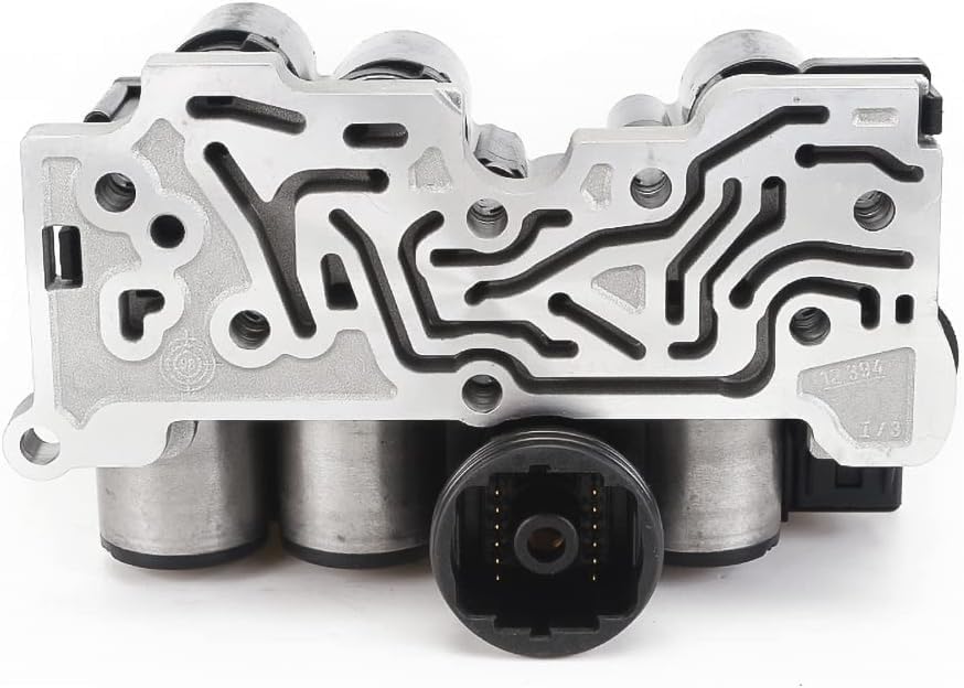
Shift complaints on a 2002-2005 Explorer or Mountaineer with the 5R55W come in a few flavors: a 1-2 that bangs, a 2-3 that flares and then lands hard, a truck that hunts between 4th and 5th on the highway, or one that seems to pick the wrong gear altogether. Owners tend to lump all of it together as "it shifts funny," but on this transmission each of those complaints points somewhere different. The 5R55W is unusual in how much of its shift feel is decided electronically. Ford's 5R55W/S has four on/off shift solenoids, three variable-force pressure control solenoids and a TCC solenoid, all on one solenoid body bolted to the valve body [1]. On top of that it uses two bands with servos in the case, which wear in their own way.
This is the order I work an Explorer that shifts wrong: codes and sensor data first, then fluid, then a pressure gauge, and only then the valve body and servos. Most of the money people waste on this unit gets spent by skipping the first two steps.
The short version: Read codes before anything else. Ford's DTC chart shows that a bad TR sensor circuit (P0705), a TFT sensor stuck high or low (P0712/P0713), or a TSS/OSS speed sensor fault (P0715-P0722) will all cause harsh shifts by themselves, because the PCM raises control pressure when it loses an input [1]. With no codes, set the fluid by the check plug method (MERCON V, TFT 81-120°F) [2], then put a gauge on the line pressure tap and compare against Ford's spec. Out-of-spec pressure points into the valve body, where the main regulator, boost sleeve and VFS modulator bores are the known wear spots [3][4].
How the 5R55W Decides a Shift
Understanding what the PCM is doing makes the rest of the diagnosis faster. Ford describes the shift solenoids SSA, SSB, SSC and SSD as normally open three-way solenoids that pick the gear by routing control pressure to the right band or clutch. The three pressure control solenoids, PC-A, PC-B and PC-C, are variable-force units that set line pressure and the apply pressure for the individual bands and clutches [1]. So the on/off solenoids decide which gear you get and the PC solenoids decide how hard it goes in.
That split matters when you read a complaint. Wrong gear, missing gear or no engine braking points at the shift solenoid side. Harsh, soft or flared shifts in gears that otherwise come in on time point at pressure: the PC solenoids, the regulator valves they feed, or a leak downstream.
The PCM also builds its pressure command from inputs. Ford lists throttle position, MAF, engine rpm (PIP), TFT, and the turbine, intermediate and output shaft speed sensors as feeding control pressure and shift scheduling. When the TP sensor fails, the PCM goes to failsafe and raises line pressure to protect the unit, which Ford says produces harsh engagements, firm shifts, an abnormal shift schedule and no lockup [1]. In other words, a bad engine sensor can make a healthy transmission feel like it is about to come apart.
Step 1: Codes and the Inputs That Cause Harsh Shifts
Pull codes with a scan tool that reads Ford PCM data, not just a generic code reader. These are the transmission-related codes from Ford's chart that matter most for a shift-quality complaint [1]:
| Code | What Ford says it means | Shift symptom Ford lists |
|---|---|---|
| P0705 | Digital TR sensor circuit short to ground or open | Increased control pressure, harsh shifts |
| P0708 | Digital TR sensor TR3A circuit open | Increased pressure, defaults to OD position in all ranges |
| P0712 / P0713 | TFT reads 315°F (short) / -40°F (open) | Firm shift feel |
| P0715 / P0717 / P0718 | TSS sensor no input or noisy signal | Harsh shifts, harsh TCC apply |
| P0720 / P0721 | OSS sensor no input or noisy signal | Harsh shifts, abnormal shift schedule |
| P0791 / P0794 | ISS sensor no input or intermittent | Harsh 2-3 shift |
| P1746 / P0796 | PC-A circuit open / PC-C circuit open | Maximum pressure, harsh engagements and shifts |
| P0750-P0765 | SSA, SSB, SSC, SSD circuit faults | Missing or wrong gears, no engine braking (SSD) |
If you have any of the sensor codes, fix that first and road test again before you condemn anything inside the case. A harsh 2-3 with a P0791 is an ISS sensor or wiring job, not a valve body.
With no codes, look at live data anyway. Watch the TFT and TFTV PIDs while the truck warms up; Ford's TFT test simply checks that both rise as the fluid warms and fall as it cools [1]. A TFT that sits at one value tells the PCM the fluid is cold or hot when it is not, and the shift schedule and pressure follow that wrong number. Ford's P1718 (no change in TFT high range) lists increased pressure, wrong TCC scheduling and harsh engagements and shifts. Also check that the TR sensor reads the position the lever is in. Ford notes a misaligned DTR sensor can cause harsh engagement and firm shifts, and it is set with a dedicated alignment tool that will not seat fully if the sensor is out of position [1].
Step 2: Check the Fluid the Ford Way
There is no dipstick on the 5R55W, and a wrong level is a common cause of erratic and hunting shifts. Ford specifies MERCON V (XT-5-QM), 12.6 qt (12.0 L) total capacity, and the level is set at the pan's check plug with the engine running and TFT between 81 and 120°F [2]. Too low and the pump pulls air on turns and stops; too high and the fluid foams, which shows up as erratic line pressure. Sonnax also points out that excess valve-to-bore clearance in a worn valve body aerates the fluid and can give a false level reading [4], so a level that keeps "changing" on a worn unit is a clue, not just an annoyance.
Step 3: Prove It With a Pressure Gauge
Electronic diagnosis tells you what the PCM is commanding. A gauge tells you what the hydraulics are actually doing. Ford's line pressure specs for the Explorer and Mountaineer are [1]:
| Range | 4.0L idle (psi) | 4.6L idle (psi) | WOT stall, both (psi) |
|---|---|---|---|
| P and N | 75-120 | 75-120 | N/A |
| R | 145-190 | 175-215 | 282-350 |
| D, 3, 2, 1 | 80-110 | 100-135 | 228-263 |
Ford also gives a method that isolates the PC solenoids: the line pressure tap reads PC-A and PC-B output, and you can turn one off with the scan tool while watching the other; a separate pressure control tap reads PC-C [1]. Pressure that is high at idle in all ranges sends you to the PC solenoids, sticking valves, or loose valve body bolts causing cross-leaks. Pressure that will not rise at stall sends you to the regulator and boost circuit.
Ford's symptom chart for harsh shifts is worth knowing by heart because it tells you which hard parts are in play for each shift [1]:
- Harsh 1-2: line pressure, sticking valves, valve body bolt cross-leaks, overdrive band and servo, direct clutch.
- Harsh 2-3: the same pressure and valve body items, plus the direct clutch, intermediate band and servo, overdrive band and servo, and the direct one-way clutch.
- Harsh 3-4: pressure, valve body, center support and direct clutch.
- Harsh 4-5: pressure, valve body, and the overdrive band and servo.
Every line starts with line pressure and the valve body. That is why the gauge comes before the pan.
Step 4: The Valve Body Wear Points
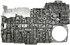
On a high-mileage Explorer with correct sensor data and bad pressure, the valve body is usually the problem, and the wear is predictable. Sonnax's 5R55 tech article says the TCC modulator bore and the main regulator bore wear first because they move the most, and that the VFS 1, 2 and 3 modulator bores wear as cycle count builds up, cutting the pressure that reaches the clutches and servos [4]. The same article makes a point every builder should take to heart: the solenoid or the servo pin bore often gets blamed when the real fault is that the VFS modulator valves cannot supply enough pressure.
Sonnax's valve body layout for the 5R55S/W ties specific complaints to specific valves [3]. A worn pressure regulator valve is listed for harsh shifts, soft shifts, delayed engagement, poor line rise and out-of-range pressure codes. Worn VFS modulator bores are listed for flare shifts, pressure control codes and low line pressure. A worn boost sleeve shows up as poor line rise, erratic line pressure, soft shifts and burnt clutches. Leaking end plugs are listed for soft, inconsistent shift feel. The way to confirm any of this before ordering parts is a wet air test or vacuum test of each bore with the valve body on the bench.
One trap on spacer plates: ATSG reported in Transmission Digest that Ford redesigned the 5R55S valve body and bonded spacer plate for 2009, changing the VFS1, VFS2 and line pressure passages, and that none of the 2009 parts retrofit to earlier units. A 2009 plate (9L2Z-7Z490-B) installed on an earlier valve body connects line pressure into the VFS2 circuit and causes a harsh 1-2 and a flared 2-3 [5]. If an Explorer came in shifting fine and left with a harsh 1-2 after valve body work, check which plate went in.
Step 5: Solenoid Body Electrical Checks
When a shift solenoid code is set or a gear is missing, test the solenoid body at the 16-pin case connector before replacing anything. Ford's procedure uses terminal 3 as the common feed, with SSA on pin 16, SSB on 15, SSC on 6, SSD on 5 and TCC on 14. Resistance from pin 3 to each shift solenoid should be 16-45 ohms, and 9-16 ohms to the TCC solenoid. Any of those terminals reading under 5 ohms to chassis ground means a shorted solenoid and a new solenoid body [1]. While you are there, command each solenoid on and off with the scan tool and listen for the click.
Ford's chart also shows what each failure feels like, which helps when the code is intermittent. An SSA shorted gives no 4th or 5th and open gives no 1st; SSB shorted gives no 1st and open gives no 3rd; an SSD fault takes away engine braking in the manual ranges [1]. If the solenoid body is replaced, the bolts are only 71 in-lb (8 N-m) and must go in the specified sequence [2]. Over-torqued or out-of-sequence bolts are one way to create the cross-leaks Ford lists under every harsh shift symptom.
5R55W Shift Solenoid Block Pack (2002-up Explorer)
When the solenoid body fails the resistance check or keeps setting shift and PC solenoid codes, this is the complete pack that bolts to the 2002-up Explorer and Mountaineer valve body.
View the 5R55W solenoid block pack →Need something else? Browse all 5R55W parts at Core Transmission Parts.
Step 6: Servos and Bands
If pressure checks good and the shift is still flared or bound up, look at the band side. The 2-3 is the 5R55W's hardest shift to get right because it is a band-to-band swap timed by the PCM, and both servos are in play. GEARS Magazine notes that a servo piston that is hard, cracked or has a torn seal can leak release oil into the apply side and hold a band on when it should be off, and that these servos often pass an air check because only the release side is damaged [6]. The same article ties 2nd and 5th slip and 2-3 bind-ups on the W/S to servo pin bore wear in the case. Our servo pin bore guide covers the sleeve repair in detail.
A quick shop test from that article: with the truck on a lift, engine running and in gear, have someone try to turn each band adjusting screw. In Drive both should turn freely. If one is tight, that band is being applied when it should not be [6].
The Fix, in Order
- Repair any input sensor or TR sensor fault and road test again.
- Set the fluid level by the check plug with TFT at 81-120°F, using MERCON V.
- Gauge line pressure and compare to Ford's table; use the PC-A/PC-B isolation test if it is off.
- Ohm the solenoid body at the case connector; replace it if a circuit is out of range or shorted.
- If pressure is wrong with good electrics, overhaul or replace the valve body, with regulator, boost and VFS modulator bores addressed.
- If shifts still flare or bind, inspect the servos, pin bores and bands.
Prevention is mostly about fluid. Ford cuts the 5R55W service interval to 30,000 miles for towing, heavy loads, hilly terrain or sustained temperatures above 90°F [2], and most Explorers are used that way. Clean fluid at the right level keeps the regulator and VFS bores from wearing as fast, and that is where most shift complaints on this unit begin.
Solenoid packs, valve bodies, shift kits and rebuild kits for the 2002-2005 Explorer and Mountaineer 5R55W, with checkout on our site.
Shop 5R55W parts →FAQ
Why does my Ford Explorer transmission shift hard?
On the 2002-2005 Explorer 5R55W, harsh shifts most often start with an input problem. Ford's DTC chart shows that a TR sensor fault, a TFT sensor stuck high or low, or a turbine or output shaft speed sensor fault makes the PCM raise control pressure, which gives harsh shifts. With no codes, low or overfilled fluid, a worn main regulator or VFS modulator bore in the valve body, or an open PC solenoid circuit are the usual causes.
What causes a 2-3 shift flare on a 5R55W?
The 2-3 on the 5R55W is a band-to-band swap, so it is sensitive to pressure and servo condition. Worn VFS modulator bores in the valve body cause flare shifts, as do servo pin bore wear and leaking servo pistons. ATSG also reported that installing a 2009 bonded spacer plate on an earlier valve body feeds line pressure into the VFS2 circuit and causes a harsh 1-2 and a 2-3 flare.
How do I test the 5R55W solenoid pack?
Disconnect the 16-pin connector at the case and measure from terminal 3, the common feed. Ford specifies 16-45 ohms to each shift solenoid (SSA pin 16, SSB pin 15, SSC pin 6, SSD pin 5) and 9-16 ohms to the TCC solenoid on pin 14. Any of those terminals reading under 5 ohms to chassis ground means the solenoid body should be replaced.
What should 5R55W line pressure be?
Ford's spec for the Explorer and Mountaineer is 80-110 psi at idle in Drive on the 4.0L and 100-135 psi on the 4.6L, rising to 228-263 psi at wide-open-throttle stall on both. Reverse is 145-190 psi at idle on the 4.0L and 175-215 psi on the 4.6L, with 282-350 psi at stall.
Sources
- Ford Motor Co. service information (Mitchell reprint) — 2002 Ford Explorer, "5R55W/S Diagnosis," on solenoid body construction, input sensor effects on pressure, the DTC chart (P0705-P1746), line pressure specifications, PC solenoid isolation, harsh shift symptom charts, solenoid connector pinout and resistance specs, and the TFT and DTR sensor tests. 5R55W/S Diagnosis (PDF)
- Ford Motor Co. service information (Mitchell reprint) — 2002 Ford Explorer, "Servicing - Explorer & Mountaineer," on MERCON V, 12.6 qt (12.0 L) capacity, the 81-120°F check-plug procedure, the 30,000-mile severe service interval, and solenoid body bolt torque of 71 in-lb. 5R55W/S Servicing (PDF)
- Sonnax — Ford 5R55S/5R55W valve body layout, on the pressure regulator valve, boost valve, VFS modulator control valve and end plug wear and the symptoms each causes. sonnax.com valve body layout
- Sonnax — "Figuring Out the 5R55 Alphabet," on TCC modulator and main regulator bore wear, VFS 1-3 modulator bore wear reducing clutch and servo pressure, aeration and false fluid level, and wet air testing. sonnax.com tech article
- Transmission Digest (ATSG Tech Talk), December 2018, "Ford 5R55S: Avoid 1-2 harsh shifts and 2-3 flared shifts," on the 2009 valve body and bonded spacer plate 9L2Z-7Z490-B and the harsh 1-2 / 2-3 flare from using it on earlier valve bodies. transmissiondigest.com
- GEARS Magazine (ATRA) — March 2017, on servo piston release-side leaks that pass an air check, 2nd/5th slip and 2-3 bind-ups from servo pin bore wear on the W/S, and the band adjusting screw test. gearsmagazine.com