Ask ten shops what kills a 4L80E and most will name a part: the direct drum, the rear band, the sun shell. Those do break. But on a high-mile unit with soft shifts, wrong gear starts, a solenoid code that clears and comes back, or a converter that shudders after a fresh rebuild, the failed part is usually not a part at all. It is clearance. Aluminum bores wear oval where a steel valve strokes thousands of times an hour, and the oil that was supposed to move a shift valve goes out the side of the bore instead. That is how a unit comes back on warranty with new frictions, a new converter and new solenoids and still shifts badly. Nobody condemned the casting.
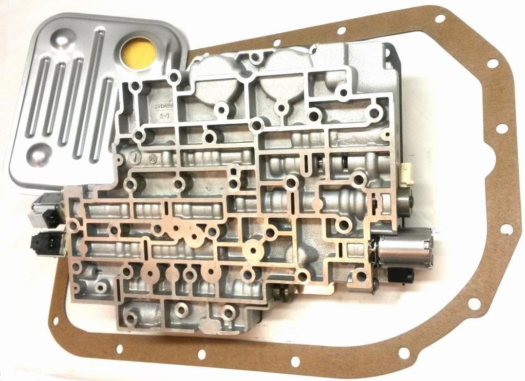
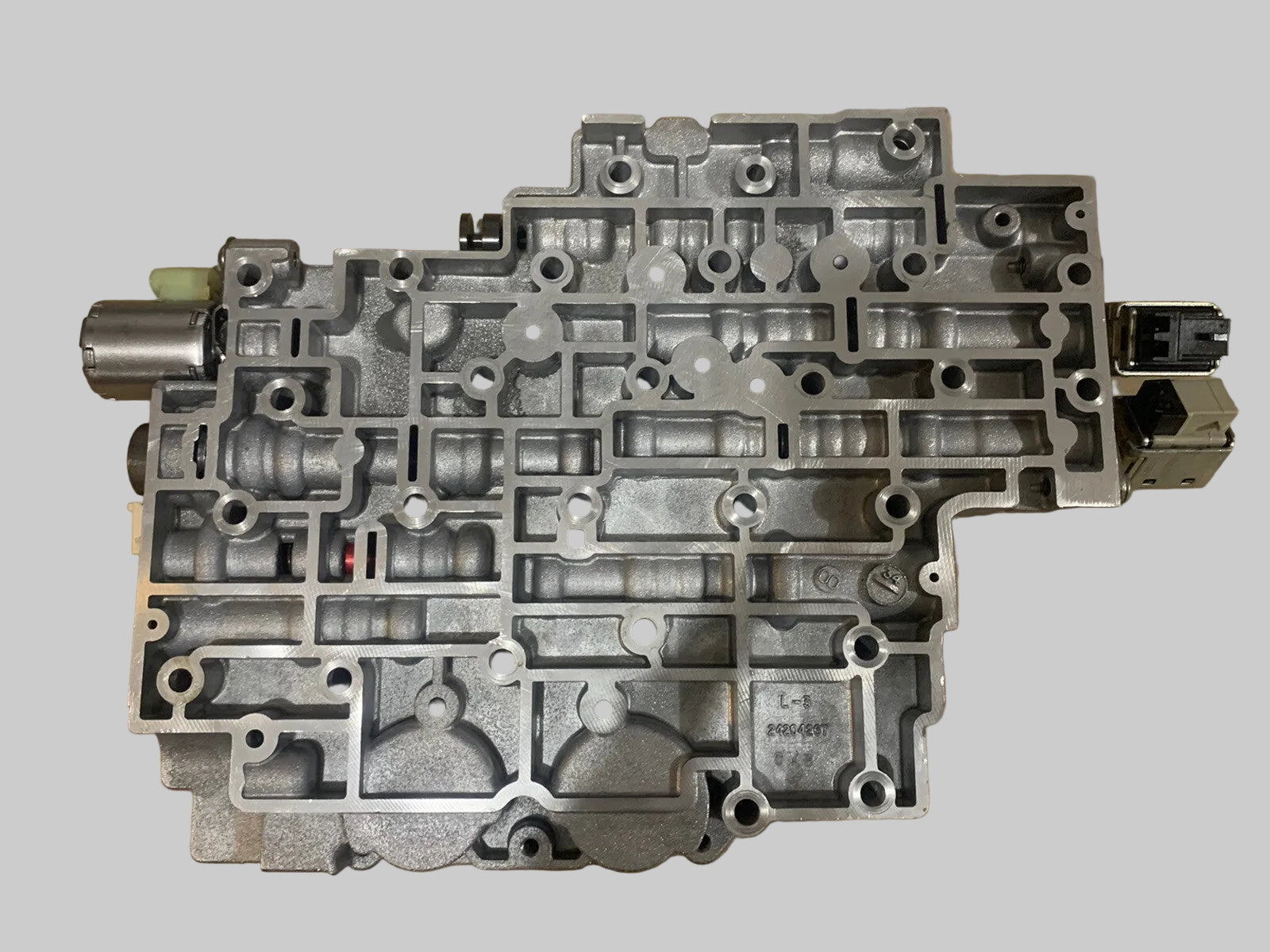
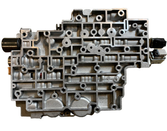
Why these particular bores wear
Not every valve in the body is a wear candidate. The ones that fail share a habit: they live in a narrow section of their bore and get worked constantly. A shift valve strokes end to end a few times per drive cycle and spends most of its life parked. A regulating valve never parks. It hunts inside a band maybe a tenth of an inch wide, putting every cycle of wear where sealing matters most — the point ATRA makes in its valve-type primer.
The actuator feed limit valve is the worst offender here, and Sonnax is direct about why: the AFL valve has a large reaction area and is heavily affected by side loading, and the EPC solenoid oscillating torque signal and AFL oil keeps it working, which accelerates bore wear. Its job is to knock line pressure down to a consistent solenoid feed — typically 80 to 115 psi — so the shift solenoids and the pressure control solenoid see a stable supply no matter what line pressure is doing.
Understand that and the symptom list stops looking random. If the AFL bore leaks, solenoid feed drops, shift valves that should stroke fully do not, and electrically perfect solenoids start behaving like they are mechanically stuck. The same lost oil never makes it back into the circuit, so line pressure sags with it. One worn bore, four complaints on the repair order.
The bores that matter, and what each one does to the truck
Sonnax numbers the 4L80E and 4L85E valve body bores 101 through 110 in its published wear guide, and the pump bores 201 through 204. Working from that map, here is the short list worth your time on a core:
- 109 — Actuator feed limit valve. Wrong gear starts, second gear starts, no fourth, clutch and band failures, solenoid performance codes. Sonnax lists OBD-I codes 68, 85, 86 and 87 here; on OBD-II trucks it surfaces as solenoid performance and ratio codes.
- 108 — TCC regulator valve. Converter shudder, burnt linings, TCC apply and release complaints. Sonnax's vacuum testing guidance says a unit with an 1870 code should have this bore checked for leakage before you condemn anything else.
- 110 — Accumulator control valve. Soft shifts and low accumulator pressure, high line pressure in Drive, low line rise in Reverse. The bore that makes a truck feel mushy on the 1-2 and hard in the driveway at once.
- 203 — Boost valve assembly (pump). This one breaks things. A wear-created cross leak at the sleeve lets reverse boost oil into the torque signal circuit: uncontrollable line rise reported upward of 500 to 600 psi, high pressure in Reverse, an audible buzz, broken direct clutch drums and cracked cases. Leakage past the aluminum balance plug adds to it.
- 203 — Pressure regulator valve (pump). Engine surge at idle, low TCC release pressure, low cooler flow.
- 101B/101C and 105 — Reverse, 3rd, and low/reverse checkball sleeves. Reverse slip or no reverse, 3rd and 4th slip, ratio codes, burnt direct clutch, no engine braking in manual low, burnt rear band.
- 107 — Manual valve. Bent valves, low line rise, delayed engagement. Less common, but free to check.
Notice how many produce the same complaint. "Slips in reverse" can be a worn checkball sleeve, a worn boost valve, or a rear band on a mismatched drum. Hence the next two sections.
Prove it in the truck first: split the circuits
Before the pan comes off, separate the problem into hydraulic, electrical and mechanical. The Sonnax TASC Force write-up on the elusive 4L80E no-reverse lays out the discipline: test line pressure in the gear that has the complaint, not just in Drive, and use a clutch and band chart to find where else that component is used. For a reverse complaint that means readings in Reverse, 3rd, 4th and manual 1st, low and high side. The logic is clean:
- 3rd and 4th present means the direct clutch applies and holds, so the drum is not your problem.
- 3rd and 4th missing points at a leaking or missing checkball, sealing rings, or the direct drum.
- Engine braking in manual 1st means the low/reverse band can hold.
The electrical half takes a minute: unplug the case connector to force the fail-safe pattern and see if reverse returns. One warning, and it applies to every pressure complaint here. Unplugged, line pressure goes to an uncontrolled maximum, which masks a leak a regulated system cannot overcome. A truck that behaves with the connector unplugged does not have a good valve body. It has a leak you just brute-forced.
Hand vacuum pump and tester
You cannot vacuum test a bore without a pump you can hold a steady reading on, and the same kit earns its keep on brake bleeding between transmission jobs.
See the Mityvac MV8000 kit →The bench test: vacuum, not eyeballs
Visual inspection finds a scored bore. It does not find an oval one, and oval is what you have. Vacuum testing seals the circuit around a valve spool and pulls air through the spool-to-bore clearance; the reading in inches of mercury is proportional to the clearance that opened up. Low reading, worn bore. The locations that matter:
- 109A — actuator feed limit valve. Test with a 1/8" shim in the balance side to hold the valve in its working position. The most important reading on the casting.
- 108A and 108B — TCC regulator valve, spring side and inboard spool.
- 110A and 110B — accumulator control valve, inboard and outboard spool.
- 102A/102B and 103A/103B — 2-3 and 1-2 shift valves, spring side and inboard land.
- 101B, 101C and 105A/105B — checkball sleeves. Tested with the body vertical so the ball seats, front down for the 3rd and reverse sleeve and up for the reverse sleeve. Wrong orientation passes a bad sleeve.
- 104A — AFL screen and O-ring. Cheap to fix, easy to overlook; a broken AFL filter shows up as second gear starts.
Two casting valleys are open to the back side and will bleed off your reading unless you plug them with foam or putty, and one orifice on the back of the casting needs a fingertip over it during the low/reverse checkball test. That is the difference between a real number and one that sends a worn body back into a truck.
The numbers to hold against
Sonnax is explicit that your pass/fail standard should be your own, logged across ten cores on your own stand, because pump capacity, gauge, spool count and even altitude move the numbers. Until you have that data, the minimums published in the individual Sonnax kit instructions are a defensible floor:
- Actuator feed limit valve: 18 in-Hg minimum after repair.
- TCC regulator valve: 16 in-Hg minimum after repair.
- Accumulator control valve: 14 and 18 in-Hg at its two test locations.
- Boost valve circuit: 18 in-Hg minimum, tested with the pump fully assembled — not on a bare pump half.
One tooling note: the 34994-VTP plate covers the valve body casting only. Pump ports get tested with the small test plate and sealing pad from the stand kit.
The fix, bore by bore
Actuator feed limit valve (109)
This is not a drop-in. The 4L80E AFL repair is a core drill, then a ream, then a sleeved valve, and the order matters — drilling has to happen before reaming. Clamp the body circuits-up, drop the drill guide in the bore, flood it with cutting fluid, and run the core drill at approximately 1000 rpm until it bottoms. Do not lean on it and do not let it grab. Clean the body thoroughly before the reamer goes in; debris left in the bore is what ruins the repair.
The sleeve should go in with slight resistance. If it slides in easily or spins, raise a small ridge around the sleeve lands with a tubing cutter, or use a liquid sleeve retainer such as Loctite 609 sparingly on the inboard end with a surface prep like Permatex 24163. That combination kicks in about 30 seconds, so install the sleeve without the valve, let it cure, then fit the valve.
Spring selection depends on which OE lineup came out: first design gets the short spring, roughly 1.25 inches; second design gets the long spring, roughly 1.75 inches. Keep the OE retainer, and on a first-design lineup the OE spacer too — which is why nothing OE gets thrown out until the new lineup is identified. Last step, and the one most commonly skipped: enlarge the AFL balance orifice in the separator plate to .052" with the drill bit supplied in the 77754-TL kit.
TCC regulator valve (108)
Easier job. The replacement valve carries a scarf-cut PTFE seal that has to be lubed heavily enough to hold its edges at or below the spool diameter, or it catches on an open port going in. Push it in spring end first, reinstall the OE roll pin, then stroke the valve with a blunt pick to confirm the seal did not hang up. If the bore fights the seal, a 15/32" counter bore chamfer at the outer bore end gives clearance — then clean out every bit of the debris you just made. The kit ships two springs and the choice is real: the.420" O.D. spring gives OE lockup feel, the.300" O.D. spring gives firmer-than-OE lockup and suits a truck that tows. Decide before assembly, not after the road test.
Boost valve and pressure regulator (pump, 203)
A drop-in with O-rings, but the year differences will bite you. Starting in 1997 the larger boost valve diameter dropped from .855" to.830" with a matching sleeve change, identified by a machined groove in the sleeve end. That cut maximum Reverse pressure by roughly 40 to 50 psi. Earlier valves can take the later design as long as both valve and sleeve change together.
On 1989 through 1991 units the OE pressure regulator valve is longer and the boost valve shorter, so a retrofit means grinding the new boost valve to .475" to.485" and the OE PR valve to .635" to.640". Install a late-design boost against an unmodified early PR valve and you get high line pressure, which is how cases get cracked. 1991-and-later PR designs need no modification. Either way, get the OE springs back in the right position — wrong location creates high pressure on its own.
Checkball sleeves
The reverse and 3rd checkball sleeves and the low/reverse checkball seat are all replaceable and all commonly leaking on a high-mile core. On a no-reverse that survived the in-vehicle tests, inspect the low/reverse servo feed passages in the case and the separator plate along with the checkballs housed in sleeves — balls 7 and 11 have a history of causing this complaint.
While you are in there
If the unit is apart for a no-reverse and the rear band is involved, check the band-to-drum match before reassembly. In 1995 GM changed both the drum surface finish and the band lining: early bands are grooved and run on a rougher drum, later bands are smooth-lined and run on a smooth-finished drum. Put a smooth-lined band on an early rough drum and the lining comes off in short order. A band that looks correct in the parts book is not automatically correct on the bench.
4L80E and 4L85E valve body components, shift kits, solenoids and EPC, filter and gasket kits, rebuild kits, and the pressure and vacuum test tools this procedure calls for — shipped fast from the USA.
Shop 4L80E parts →The short version
- At high mileage this unit fails on bore clearance, not broken parts. Check the AFL valve first — a leaking 80 to 115 psi solenoid feed gives you wrong gear starts, solenoid and ratio codes, and low line pressure at once.
- Split the circuits before teardown. Unplugging the case connector masks leaks with max pressure.
- Minimums after repair: 18 in-Hg AFL, 16 in-Hg TCC regulator, 14 and 18 in-Hg accumulator control, 18 in-Hg boost with the pump assembled.
- The AFL fix is drill at 1000 rpm, ream, sleeve, correct spring for the OE design, and open the plate orifice to.052". All of it, or none of it.
- 1997-up boost valve is.830" not.855"; 1989-1991 retrofits require grinding both the boost and PR valves to spec.
Sources
- Sonnax — "GM 4L80-E, 4L85-E Vacuum Test Guide" (Critical Wear Areas & Vacuum Test Locations, with the 34994-VTP vacuum test plate kit instructions). Backs the bore identification map 101 through 110 for the valve body and 201 through 204 for the pump, the per-bore symptom lists (AFL wrong gear starts, second gear starts, no fourth and codes 68, 85, 86 and 87; TCC regulator shudder and burnt converter; accumulator control soft shifts, high line in Drive and low line rise in Reverse; manual valve bent valves and delayed engagement; broken AFL filter as second gear starts), the orifice locations 101B, 101C, 102A/B, 103A/B, 104A, 105A/B, 108A/B, 109A and 110A/B, the 1/8" shim in the AFL balance side, the vertical checkball-sleeve orientations, the casting valleys that must be plugged with foam or putty, and the note that the 34994-VTP plate does not cover pump ports. sonnax.com
- Sonnax — "Uncovering the Root Cause of Pressure & Complaints: The Critical Role of Solenoid Modulator & AFL Valves." Backs the function of the actuator feed limit valve, the typical 80 to 115 psi regulated solenoid feed range, and the mechanism by which high or low AFL feed causes shift valves to over- or under-stroke, producing shift concerns, clutch failures, solenoid codes and TCC apply and release complaints. sonnax.com
- Sonnax — Actuator Feed Limit Valve Kit 34200-16K installation instructions (PDF, revision 08-31-21) and product page. Backs the AFL valve's large reaction area and side-loading wear mechanism, the EPC solenoid oscillation that accelerates it, the requirement to core drill before reaming, the approximately 1000 rpm drilling speed and cutting-fluid step, the tubing-cutter and Loctite 609 / Permatex 24163 sleeve retention methods with the 30-second cure, the first-design short spring (about 1.25") versus second-design long spring (about 1.75") selection, the.052" separator plate balance orifice enlargement, the 77754-TL tool kit requirement, and the 18 in-Hg minimum vacuum after repair. sonnax.com (PDF)
- Sonnax — TCC Regulator Valve Kit 34994-01K installation instructions (PDF, revision 06-26-20). Backs the scarf-cut PTFE seal lubrication and installation procedure, the spring-end-first insertion and OE roll pin retention, the blunt-pick stroke check, the 15/32" counter bore chamfer allowance, the.420" O.D. spring for OE lockup feel versus the.300" O.D. spring for firmer lockup best suited to towing applications, and the 16 in-Hg minimum vacuum after repair. sonnax.com (PDF)
- Sonnax — Boost Valve Kit 34200-01K product page and installation instructions (PDF, revision 02-07-19). Backs the reverse-boost cross leak at the sleeve, uncontrollable line rise upward of 500 to 600 psi, high Reverse line pressure, buzzing, broken direct clutch drums and cases, leakage past the aluminum balance plug, the 1997 boost valve diameter change from.855" to.830" with matching sleeve and the resulting 40 to 50 psi reduction in maximum Reverse pressure, the 1989-1991 retrofit grind dimensions of.475"-.485" for the boost valve and.635"-.640" for the OE pressure regulator valve, the warning that incorrect OE spring position creates high pressure, and the 18 in-Hg minimum vacuum with the pump fully assembled. sonnax.com
- Transmission Digest / Sonnax TASC Force — "Diagnosing the Elusive No Reverse with the 4L80-E," Randall Schroeder. Backs the split-the-circuits diagnostic method, testing line pressure in Reverse, 3rd, 4th and manual 1st against the pressure chart on both the low and high side, the interpretation of 3rd/4th presence and manual-1st engine braking, the case-connector unplug test and the warning that uncontrolled max line pressure masks leaking, the inspection of low/reverse servo feed passages and the checkballs housed in sleeves (balls 7 and 11), and the 1995 change to band lining and drum surface finish that causes rapid band failure and no reverse when grooved and smooth-lined parts are mismatched. transmissiondigest.com
- Gears Magazine (ATRA) — "Transmissions 101: Understanding Valve Types." Backs the classification of valve body valves into regulator, switch and servo types, the property that regulating valves operate within a relatively narrow section of the bore where sealing is most critical, and the point that solenoid-feed regulating valves of this family are especially prone to bore wear that causes shift and engagement issues. gearsmagazine.com